EP0369033A1 - Joint metallique d'etancheite - Google Patents
Joint metallique d'etancheite Download PDFInfo
- Publication number
- EP0369033A1 EP0369033A1 EP89906428A EP89906428A EP0369033A1 EP 0369033 A1 EP0369033 A1 EP 0369033A1 EP 89906428 A EP89906428 A EP 89906428A EP 89906428 A EP89906428 A EP 89906428A EP 0369033 A1 EP0369033 A1 EP 0369033A1
- Authority
- EP
- European Patent Office
- Prior art keywords
- pressure generating
- surface pressure
- base
- metal gasket
- materials
- Prior art date
- Legal status (The legal status is an assumption and is not a legal conclusion. Google has not performed a legal analysis and makes no representation as to the accuracy of the status listed.)
- Granted
Links
- 239000002184 metal Substances 0.000 title claims abstract description 66
- 229910052751 metal Inorganic materials 0.000 title claims abstract description 66
- 239000000463 material Substances 0.000 claims description 108
- 239000003566 sealing material Substances 0.000 claims description 56
- 230000002708 enhancing effect Effects 0.000 claims description 2
- 238000007789 sealing Methods 0.000 abstract description 30
- 239000007788 liquid Substances 0.000 abstract description 2
- 239000000758 substrate Substances 0.000 abstract 4
- 239000003795 chemical substances by application Substances 0.000 abstract 2
- 230000005489 elastic deformation Effects 0.000 abstract 1
- 238000005452 bending Methods 0.000 description 10
- 239000011324 bead Substances 0.000 description 9
- 239000002987 primer (paints) Substances 0.000 description 9
- 238000002485 combustion reaction Methods 0.000 description 8
- 238000000034 method Methods 0.000 description 7
- XLYOFNOQVPJJNP-UHFFFAOYSA-N water Substances O XLYOFNOQVPJJNP-UHFFFAOYSA-N 0.000 description 7
- 239000007789 gas Substances 0.000 description 6
- 239000003921 oil Substances 0.000 description 6
- 230000008569 process Effects 0.000 description 6
- 229910000831 Steel Inorganic materials 0.000 description 5
- 239000011248 coating agent Substances 0.000 description 5
- 238000000576 coating method Methods 0.000 description 5
- 229920005989 resin Polymers 0.000 description 5
- 239000011347 resin Substances 0.000 description 5
- 239000010959 steel Substances 0.000 description 5
- 229920001971 elastomer Polymers 0.000 description 4
- 230000000694 effects Effects 0.000 description 3
- 238000003754 machining Methods 0.000 description 3
- 229920000459 Nitrile rubber Polymers 0.000 description 2
- 229910001301 Spiegeleisen Inorganic materials 0.000 description 2
- 230000009471 action Effects 0.000 description 2
- 239000010425 asbestos Substances 0.000 description 2
- 238000006243 chemical reaction Methods 0.000 description 2
- 239000000567 combustion gas Substances 0.000 description 2
- 239000012141 concentrate Substances 0.000 description 2
- 238000001816 cooling Methods 0.000 description 2
- 239000000498 cooling water Substances 0.000 description 2
- 239000010949 copper Substances 0.000 description 2
- 238000010030 laminating Methods 0.000 description 2
- 239000010687 lubricating oil Substances 0.000 description 2
- 238000005461 lubrication Methods 0.000 description 2
- 238000004519 manufacturing process Methods 0.000 description 2
- 239000007769 metal material Substances 0.000 description 2
- 238000007747 plating Methods 0.000 description 2
- 229910052895 riebeckite Inorganic materials 0.000 description 2
- 229920002379 silicone rubber Polymers 0.000 description 2
- 239000004945 silicone rubber Substances 0.000 description 2
- 238000005245 sintering Methods 0.000 description 2
- 238000005507 spraying Methods 0.000 description 2
- 239000010935 stainless steel Substances 0.000 description 2
- 229910001220 stainless steel Inorganic materials 0.000 description 2
- RYGMFSIKBFXOCR-UHFFFAOYSA-N Copper Chemical compound [Cu] RYGMFSIKBFXOCR-UHFFFAOYSA-N 0.000 description 1
- 239000004809 Teflon Substances 0.000 description 1
- 229920006362 Teflon® Polymers 0.000 description 1
- 229910045601 alloy Inorganic materials 0.000 description 1
- 239000000956 alloy Substances 0.000 description 1
- 230000008859 change Effects 0.000 description 1
- 238000003486 chemical etching Methods 0.000 description 1
- 229910052802 copper Inorganic materials 0.000 description 1
- 238000005520 cutting process Methods 0.000 description 1
- 238000009826 distribution Methods 0.000 description 1
- 238000009713 electroplating Methods 0.000 description 1
- 238000004880 explosion Methods 0.000 description 1
- 238000000227 grinding Methods 0.000 description 1
- 239000003779 heat-resistant material Substances 0.000 description 1
- 238000003698 laser cutting Methods 0.000 description 1
- 238000004021 metal welding Methods 0.000 description 1
- 239000000203 mixture Substances 0.000 description 1
- 230000004048 modification Effects 0.000 description 1
- 238000012986 modification Methods 0.000 description 1
- 229920001296 polysiloxane Polymers 0.000 description 1
- 230000009467 reduction Effects 0.000 description 1
- 239000012858 resilient material Substances 0.000 description 1
- 238000005480 shot peening Methods 0.000 description 1
- 229920002050 silicone resin Polymers 0.000 description 1
- 238000005482 strain hardening Methods 0.000 description 1
- 229920003002 synthetic resin Polymers 0.000 description 1
- 239000000057 synthetic resin Substances 0.000 description 1
Images


Classifications
-
- F—MECHANICAL ENGINEERING; LIGHTING; HEATING; WEAPONS; BLASTING
- F16—ENGINEERING ELEMENTS AND UNITS; GENERAL MEASURES FOR PRODUCING AND MAINTAINING EFFECTIVE FUNCTIONING OF MACHINES OR INSTALLATIONS; THERMAL INSULATION IN GENERAL
- F16J—PISTONS; CYLINDERS; SEALINGS
- F16J15/00—Sealings
- F16J15/02—Sealings between relatively-stationary surfaces
- F16J15/06—Sealings between relatively-stationary surfaces with solid packing compressed between sealing surfaces
- F16J15/08—Sealings between relatively-stationary surfaces with solid packing compressed between sealing surfaces with exclusively metal packing
- F16J15/0818—Flat gaskets
-
- F—MECHANICAL ENGINEERING; LIGHTING; HEATING; WEAPONS; BLASTING
- F16—ENGINEERING ELEMENTS AND UNITS; GENERAL MEASURES FOR PRODUCING AND MAINTAINING EFFECTIVE FUNCTIONING OF MACHINES OR INSTALLATIONS; THERMAL INSULATION IN GENERAL
- F16J—PISTONS; CYLINDERS; SEALINGS
- F16J15/00—Sealings
- F16J15/02—Sealings between relatively-stationary surfaces
- F16J15/06—Sealings between relatively-stationary surfaces with solid packing compressed between sealing surfaces
- F16J15/10—Sealings between relatively-stationary surfaces with solid packing compressed between sealing surfaces with non-metallic packing
- F16J15/12—Sealings between relatively-stationary surfaces with solid packing compressed between sealing surfaces with non-metallic packing with metal reinforcement or covering
- F16J15/121—Sealings between relatively-stationary surfaces with solid packing compressed between sealing surfaces with non-metallic packing with metal reinforcement or covering with metal reinforcement
- F16J15/122—Sealings between relatively-stationary surfaces with solid packing compressed between sealing surfaces with non-metallic packing with metal reinforcement or covering with metal reinforcement generally parallel to the surfaces
- F16J15/123—Details relating to the edges of the packing
-
- F—MECHANICAL ENGINEERING; LIGHTING; HEATING; WEAPONS; BLASTING
- F16—ENGINEERING ELEMENTS AND UNITS; GENERAL MEASURES FOR PRODUCING AND MAINTAINING EFFECTIVE FUNCTIONING OF MACHINES OR INSTALLATIONS; THERMAL INSULATION IN GENERAL
- F16J—PISTONS; CYLINDERS; SEALINGS
- F16J15/00—Sealings
- F16J15/02—Sealings between relatively-stationary surfaces
- F16J15/06—Sealings between relatively-stationary surfaces with solid packing compressed between sealing surfaces
- F16J15/08—Sealings between relatively-stationary surfaces with solid packing compressed between sealing surfaces with exclusively metal packing
- F16J15/0818—Flat gaskets
- F16J2015/0856—Flat gaskets with a non-metallic coating or strip
Definitions
- the present invention relates to a metal gasket. More particularly, the present invention relates to a metal gasket for making gas-tight joints, for example, between the cylinder head of an internal combustion engine and the cylinder block or between the joint surfaces of pipe flanges, and maintaining the gas-tightness for a long period of time.
- Asbestos gaskets, metallic gaskets, and gaskets formed by laminating asbestos and metallic materials have heretofore been known as engine cylinder head gaskets and gas sealing gaskets for turbochargers.
- gaskets for engine cylinder heads are required to improve the sealing performance upon demand for reduction in the size and weight of engines.
- metal gaskets have recently been used.
- Japanese Utility Model Application Laid-Open Publication (KOKAI) No. 57-59952 JP, U, 57-59952 discloses a gasket wherein a gasket base is elastically deformed to form a plurality of corrugate projections at the outer periphery of a combustion chamber, that is, a gasket provided with beads. The gasket is pressed from both sides of the beads, thereby deforming the beads, and thus improving the sealing performance by making use of the restitution of the deformed beads.
- This gasket has excellent sealing performance. However, although the sealing performance is improved, when the gasket is clamped from both sides thereof, the beads are deformed into a flat surface and, at this time, stress concentrations occur at the angular portions of the beads. During use of the gasket for a long period of time, the metal constituting the portions having stress concentrations is fatigued by vibrations caused by explosion in the engine and this fatigue of the metal may cause breakage or weaken the elastic restoring force even if the gasket is not broken. In addition, the gasket needs a bending process to form corrugate beads in manufacture. The bending process causes work hardening and strain in the gasket base, thus the base being weakened in terms of the metallographic structure. It is also necessary to prepare a press die for the bending process.
- JP, U, 60-18247 discloses a metal gasket made from a steel plate wherein beads which are in the form of recesses and projections, that is, annular grooves, are formed on both surfaces of the metal gasket so as to surround a water hole and the annular grooves are coated with a sealing material consisting essentially of a silicone resin.
- This gasket needs a bending process to form beads in the same way as in the case of the above-described gasket.
- This gasket is a water hole gasket for waterproof sealing and has no idea for sealing engine cylinder bores that are exposed to high-temperature flame heat.
- the gasket is compressed unevenly, resulting in the sealing effectiveness varying depending upon the position on the gasket.
- gaskets have a tendency to be clamped in such a manner that the bolted portions and vicinities are strongly clamped, and the remoter therefrom, the lower the level of clamping force. This is due to the deformation of the cylinders and the cylinder head. Since cylinders and cylinder heads of engines which are reduced in size and weight as in recent years have a tendency to be reduced in the wall thickness, uneven deformation is unavoidable.
- the present invention was made with the foregoing technical background to attain the following objects.
- An object of the present invention is to provide a metal gasket which has an extremely simple structure and yet exhibits high sealing effectiveness.
- Another object of the present invention is to provide a metal gasket which is capable of sealing with uniform surface pressure.
- Still another object of the present invention is to provide a metal gasket in which stress concentration is unlikely to occur.
- a further object of the present invention is to provide a metal gasket which is capable of completely sealing an internal pressure gas with a weak surface pressure.
- a still further object of the present invention is to provide a metal gasket which has excellent heat resistance.
- a still further object of the present invention is to provide a metal gasket which is designed so that the adherability of a surface pressure generating material to the surface of the gasket base is improved.
- a metal gasket comprising: a planar base which is a metal plate provided with a necessary hole and having two parallel surfaces; and surface pressure generating materials provided on the obverse and reverse surfaces, respectively, of the base at the outer periphery of the hole to be sealed in such a manner that the widthwise center positions of the surface pressure generating materials are spaced apart from each other.
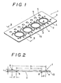
- the metal gasket 1 shown in Fig. 1 is Embodiment 1-1 in which the present invention is applied to a gasket for an automotive engine and in which the metal gasket 1 is interposed between a cylinder head and cylinders.
- the metal gasket 1 has four cylinder bores 2, a plurality of bolt holes 3, water holes 4 and oil holes 5.
- the cylinder bores 2 have substantially the same diameter as that of the combustion chambers of the engine and correspond to the respective combustion chambers.
- the bolt holes 3 are adapted for passing bolts to secure the cylinders to the cylinder head.
- the water holes 4 are adapted to pass cooling water for cooling the engine.
- the oil holes 5 are adapted to pass a lubricating oil for lubrication.
- the base 10 is a resilient metal plate. As a material for the metal plate, although there are a variety of known materials, any heat-resistant and resilient material may be employed, for example, a heat-resistant alloy, steel plate (SS material), clad metal (SK), stainless steel (SUS), etc.
- the base 10 is formed by a known machining means, for example, blanking, laser cutting, etc.
- Fig. 2 is a sectional view taken along the line II-II of Fig. 1.
- a sealing material A having a diameter D l is attached to the outer periphery of the cylinder bore 2 in the gasket 1.
- the sealing material A is coated in the shape of a semicircle or a rectangle in the cross-section.
- a material for the sealing material A a known material, for example, a silicone rubber, a fluorine-contained rubber or resin, is used.
- a sealing material B having a diameter D 2 is attached to the surface reverse to the surface having the sealing material A attached thereto in concentric relation to the sealing material A and at the inner periphery of it.
- the positions of the sealing materials A and B are offset from each other by a distance in the radial direction.
- the sealing materials A and B in this embodiment have sealing properties. However, the sealing properties are not necessarily needed, and any material which is capable of deforming the base 10 to thereby generate surface pressure may be employed, as described later. However, if the surface pressure generating material has both elasticity and sealing properties as in this embodiment, it is further possible to ensure the sealing performance and the performance of following up the deformation of the base 10 under low surface pressure. It should be noted that the sealing performance can be ensured at the side of the gasket body which is reverse to the side where the surface pressure generating material is provided. Accordingly, "sealing material" is herein synonymous with "surface pressure generating material”.
- each of the sealing materials A and B from the corresponding surface of the gasket 1 may be varied depending upon the circumferential position thereof. This is because, when the cylinder head and the cylinders are clamped by means of bolts, the gap therebetween varies depending upon the circumferential position, as described above: the closer to the bolts, the higher the level of clamping force and the smaller the gap; the remoter from the bolts, the greater the gap. Since the level of pressure with which the cylinder head is clamped by means of bolts has previously been set as being a designed pressure, the amount of gap described above can be measured.
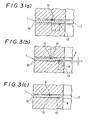
- Figs. 3(a), 3(b) and 3(c) are sectional views showing th process of deformation of the gasket 1 when the cylinder head and the cylinders are clamped by means of cylinder head clamping bolts.
- Fig. 3(a) shows the state at the time of starting the clamping operation
- Fig. 3(b) shows the state in the middle of the clamping operation
- Fig. 3(c) shows the state at the time of completion of the clamping operation.
- Counterforces P 1 and P 2 from the points 12 and 13 of contact of the sealing materials A and B act in such a manner as to push the base 10, thus causing the base 10, which is a flat plate, to be deformed into a partially curved plate against the elastic force therefrom.
- the base 10 is made from a metal plate having spring rigidity, counterforces are produced from the inside of the base 10 so as to resist the deformation. These counterforces cause action and reaction between the base 10 on the one hand and the cylinder head and the cylinders on the other in such a manner that these members push against each other, thus enabling the cylinder head and the cylinders to be hermetically sealed. Since the thicknesses of the sealing materials A and B have been predetermined in accordance with the level of counterforce to the clamping force, clamping can be effected with uniform surface pressure.
- Fig. 4 shows Embodiment 1-2 in which a fire guard 11 is provided on the base 10 at the side thereof which is closer to the combustion chamber 2 to protect the base 10 from flames from the combustion chamber 2.
- the fire guard 11 is provided only on a part of one side of the base 10.
- the fire guard 11 is formed from a material which has excellent high-temperature resistance by a known means, for example, plating, spraying, welding of metal plate, sintering, etc.
- the height of the sealing material B is greater than that of the fire guard 11 by A h. Since the fire guard 11 is not deformed when the base 10 is clamped from both sides thereof, the portion corresponding to the height A h alone functions as an interference.
- FIG. 5 shows Embodiment 1-3 in which the fire guard 11 is provided on each of the obverse and reverse sides of the gasket base 10.
- Fig. 6 shows Embodiment 1-4 in which the base 10 comprises two plates and is provided with the fire guard 11 which is inserted into the middle thereof in the thicknesswise direction.
- the sealing materials A and B are coated on the obverse and reverse sides, respectively, of the base 10 at the outer periphery of the cylinder bore 2 in concentric relation to it.
- bolts are inserted into the bolt holes 3, respectively, to clamp together the cylinders and the cylinder head.
- the clamping force acting between the cylinders and the cylinder head is strong around each bolt, and the remoter from each bolt, the lower the level of the clamping force. This is because the cylinders and the cylinder head are deformed. The amount of deformation is determined when the bolt tightening force is determined.
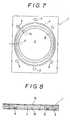
- Fig. 7 shows Embodiment 1-5 in which the spacing between the sealing materials A and B in the radial direction of the cylinder bore 2 is varied in accordance with the change in the amount of deformation.
- the spacing is set at a relatively short distance 1 1
- the spacing is set at a relatively long distance 1 2
- the position of the sealing material A is varied so that the condition of l 1 ⁇ l 2 is satisfied.
- the sealing material B is positioned so as to define a concentric circle with respect to the cylinder bore 2.
- the arrangement may be such that the sealing material A is provided so as to be concentric with the cylinder bore 2 and the sealing material B, which is closer to the cylinder bore 2, is varied in the distance between the same and the sealing material A.
- the thickness of each sealing material may be varied.
- Fig. 8 shows Embodiment 1-6 in which the metal gasket 1 is sandwiched between soft steel plates 15 which are provided over the upper and lower sides, respectively, of the gasket 1.
- the soft steel plates 15 are incorporated into the engine, together with the metal gasket 1, the steel plates 15, which are soft, are elastically deformed and enter the spaces defined by tool marks (caused by the coarseness of the loci of cutting and grinding tools) formed in the cylinder head and the cylinders. Accordingly, even if the cylinders and the cylinder head thermally expand and contract, there is no fear of the sealing materials A and B being deformed by being cut or scraped off by the tool marks.
- the sealing materials A and B in the foregoing embodiments are attached directly to the base 10 of the metal gasket 1. There are, however, cases where the sealing materials A and B do not sufficiently adhere to the base 10, depending upon the material thereof.
- the following embodiments are designed to improve the adherability.
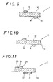
- Fig. 9 is an enlarged view of a portion including the sealing materials A and B, which shows Embodiment 2-1 in which roughened surfaces 21 are formed on the surfaces of the base 10 of the metal gasket 1.
- the roughened surfaces 21 are formed so as to be higher in the degree of unevenness than the other portions of the surfaces of the base 10. More specifically, the roughened surfaces 21 are surface portions having minute geometric deviations from a geometrically ideal surface, which is generally known as roughness. Roughness is defined by irregularities which are formed on a surface at smaller intervals than the depth to such an extent that they are recognizable by the sense of touch and visible to the naked eye (about 5 to 15p in this embodiment).
- the roughened surfaces 21 may be formed by a known machining method, for example, sandblast, shot peening, electroplating, chemical etching, etc.
- the roughened surfaces 21 are formed only at the portions where the sealing materials A and B are to be attached. Thus, the adhesion between the sealing materials A, B and the base 10 increases.
- Fig. 10 shows Embodiment 2-2 in which roughened surfaces 21 are provided all over the surfaces of the base 10 by means of satinizing. Since this base 10 is not partially machined, machining of the roughened surfaces 21 is easier than in the case of the foregoing embodiment.
- Fig. 11 shows Embodiment 2-3 which employs a rigid surface pressure generating material 30 and a soft surface pressure generating material 31.
- the rigid surface pressure generating material 30 is herein formed by means, for example, of plating, spraying or sintering.
- the rigid surface pressure generating material 30 has a rectangular cross-sectional configuration.
- the soft surface pressure generating material 31 is formed from a non-metallic material such as a resin, silicone, rubber, etc.
- the rigid surface pressure generating material 30 since the rigid surface pressure generating material 30 is used, the amount of deformation of the rigid surface pressure generating material 30 is small even when the cylinder head and the cylinders are clamped together; therefore, the rigid surface pressure generating material 30 serves as a stopper. Accordingly, the amount of soft surface pressure generating material 31 necessary to use is small. Even if the base 10 is so thick that it is not readily deformed, the rigid surface pressure generating material 30 enables deformation of the base 10. In addition, since the rigid surface pressure generating material 31 is used in combination with the soft surface pressure generating material 31, it is possible to draw out the advantages of both the surface pressure generating materials 30 and 31.
- Fig. 12 shows Embodiment 2-4 in which a rigid surface pressure generating material 30 and a soft surface pressure generating material 31 are used in combination in the same way as in the foregoing modification.
- the soft surface pressure generating material 31 is disposed on each side of the base 10 in such a manner that the material 31 provided on the obverse surface and that on the reverse surface sandwich the base 10. In comparison with the foregoing embodiment, this embodiment is effective when the sealing area is narrow.
- Fig. 13 shows Embodiment 2-5 in which a rigid surface pressure generating material 30 and a soft surface pressure generating material 31 are similarly used in combination in such a manner that the surface of the rigid surface pressure generating material 30 is covered with the soft surface pressure generating material 31.
- the outer surface of the rigid surface pressure generating material 30 having a rectangular cross-sectional configuration is covered with the soft surface pressure generating material 31.
- Fig. 14 shows Embodiment 2-6 in which a rigid surface pressure generating material 30 and a soft surface pressure generating material 31 are similarly used in combination. This is used in a case where the sealing area is further narrower than in the case of the foregoing embodiment.
- the base 10 in Embodiment 2-6 has been slightly bent in advance so as to protrude as illustrated, thus forming a step t.
- This step t is, however, not formed by deforming the base 10 to a substantial extent as in the prior art, and it is not intended to utilize the step t positively to generate surface pressure.
- a rigid surface pressure generating material 30 is formed to a thickness T which is greater than the step t.
- a soft surface pressure generating material 31 is attached to the side surface of the rigid surface pressure generating material 30. This arrangement is to prevent the sealing surface of a cylinder or the cylinder head from being damaged by the edge of the base 10 slanted due to deformation during the clamping operation.
- the base 10 may be flat, as a matter of course.
- the metal gasket 1 shown in Figs. 15(a) and 15(b) is Embodiment 3 in which the present invention is applied to a gasket for an automotive gasoline engine.
- the gasket 1 has two cylinder bores 2, water holes 3, bolt holes 4, oil holes 5, etc.
- Each cylinder bore 2 corresponds to a combustion chamber of the engine.
- the bolt holes 4 are adapted for passing bolts to secure the cylinders to the cylinder head.
- the water holes 3 are adapted to pass cooling water for cooling the engine.
- Fig. 15(b) is a sectional view taken along the line b-b of Fig. 15(a).
- Both the obverse and reverse surfaces of the base 10 are coated with a primer 41 for the purpose of satisfactorily bonding a sealing material to the base 10.
- a sealing material 42 having a high gas sealing performance is uniformly bonded, that is, laminated, over the primer 41 by means of coating or laminating.
- the primer 41 preferably has adhesion to both the material of the base 10 and the sealing material 42.
- a material for the primer 41 is selected and determined on the basis of the relationship between the sealing material 42 and the material of the base 10 which are selected.
- the primer 41 is not necessarily needed in practice because it is merely provided for the purpose of improving the adhesion of the sealing material 42 to the base 10.
- the sealing material 42 consists essentially of a resin having sealing properties and excellent oil resistance and heat resistance, which is selected from among 1 nitrile rubber (NBR), 2 silicone rubber, 3 fluorine-contained rubber, 4 Teflon resin and 5 fluorine-contained resin.
- the sealing material 42 may be a mixture of the above-mentioned materials.
- the sealing material 42 in this embodiment differs in function from the sealing material in the foregoing embodiments.
- the sealing material 42 does not serve to generate surface pressure but mainly serves to improve the sealing performance.
- Surface pressure generating materials 43a, 43b, 43c and 43d are attached to the upper side of the sealing material 41 along the outer peripheries of the corresponding bores, that is, the cylinder bores 2, the oil holes 5, the water holes 3, etc.
- the surface pressure generating material 43a is concentrically attached along the outer periphery of each cylinder bore 2.
- the surface pressure generating materials 43b are provided on the reverse surface of the base 10.
- Each surface pressure generating material 43b is located at the outer side of the corresponding surface pressure generating material 43a as viewed from the center of the corresponding cylinder bore 2. More specifically, the center position of the surface pressure generating material 43a is offset from that of the surface pressure generating material 43b by a distance l 2 in the radial direction of the cylinder bore 2.
- the surface pressure generating materials 43c and 43d are attached to the obverse and reverse surfaces, respectively, of the base 10 along the outer periphery thereof in the same way as the above.
- the distance between these surface pressure generating materials is Jl .
- the relationship between the two distances is l 1 >l 2 .
- the cylinder bores 2 are, as a matter of course, required to be more gas-tight than the other holes from the viewpoint of the operation of the internal combustion engine. Therefore, the surface pressure generating materials 43a and 43b are disposed closer to each other, i.e., at the distanced.
- a cylinder 46 and a cylinder head 45 are clamped together by means of clamping bolts with the metal gasket 1 interposed therebetween, the surface of each surface pressure generating material, which is soft, is first deformed (see Fig. 16).
- the bending angle of the base 10 is relatively large for the distance 1 2 and relatively small for the distance l 1 . More specifically, the angle 6 2 is relatively large and the angle ⁇ 1 is relatively small in the example shown in Fig. 16.
- the angle is large also means that the bending stress that acts on the base 10 is large.
- the counterforces to the bending stress cause action and reaction between the cylinder head 45 and the cylinder 46, thus bringing these two members into close contact with each other. Therefore, the gas sealing effectivenss is enhanced.
- the sealing materials 42 are coated or laminated over the obverse and reverse surfaces of the base 10, the sealing materials 42 come into close contact with the joint surface 48 of the cylinder head 45 and the joint surface 47 of the cylinder 46, respectively, thus further improving the sealing performance.
- Fig. 17 shows Embodiment 3-2 in which a metal gasket 50 has slits or punched holes provided in the vicinities of bolt holes, respectively.
- a surface pressure generating material 52a is attached along the outer periphery of a cylinder bore 51.
- the metal gasket 50 has a surface pressure generating material 52b attached to the reverse surface thereof at the outer periphery of the surface pressure generating material 52a.
- Two slits 54 and two punched holes 53 are formed on the same circumference which is at the outer periphery of the surface pressure generating material 52b in such a manner that the slots 54 and the holes 53 are in opposing relation to each other.
- a bolt hole 55 is bored at the outer periphery of each of the slits 54 and punched holes 53.
- deformation caused by the bolt tightening pressure is absorbed by the slits 54 and the punched holes 53 and therefore is unlikely to reach the vicinity of the cylinder bore 51.
- Fig. 18 shows Embodiment 3-3 in which a metal gasket 60 is covered with a grommet 62.
- the grommet 62 is made of a material such as Spiegeleisen (SP), stainless steel (SUS), copper (Cu), etc.
- SP Spiegeleisen
- SUS stainless steel
- Cu copper
- the portion of the base 10 which faces a cylinder bore 61 is exposed to high-temperature combustion gas.
- the grommet 62 prevents the base 10, the primers 41 and the sealing materials 42 from damage by the combustion gas.
- the grommet 62 is not bonded to the sealing material 42.
- the grommet 62 which has a plate-like shape, is merely placed on the surface of one sealing material 42 and bent at one end thereof which faces the cylinder bore 61 in the shape of a U, thus defining a bent portion 64.
- a surface pressure generating material 63a is attached to the surface of the grommet 62.
- a surface pressure generating material 63b is attached to the surface of the sealing material 42 on the side reverse to the side where the surface pressure generating material 63a is provided.
- the grommet 62 is deformed when the cylinder and the cylinder head are clamped together, and thereby secured.
- Fig. 19 shows Embodiment 3-4 in which a grommet 72 is attached at a position which faces a cylinder bore 71 in the same way as in the foregoing embodiment.
- the grommet 72 is provided only at a portion which faces the cylinder bore 71.
- the grommet 72 is an annular member having a U-shaped cross-sectional configuration.
- Surface pressure generating materials 73a and 73b are disposed on the respective surfaces of the sealing materials 42 while being spaced apart from each other in the same way as the above.
- the height t 2 of each of the surface pressure generating materials 73a and 73b is greater than the plate thickness t 1 of the grommet 72, i.e., t 2 >t l . This height difference is a distance within which the base 10 is to be deformed by bending.
- the plate thickness of the portion where the grommet 72 is attached functions as a stopper and prevents the gasket 70 from being pressed in excess of the thickness.
- portions which are close to clamping bolts are pressed by strong surface pressure to the overall thickness of the base 10, the primers 41 and the sealing materials 42.
- the surface pressure generating materials 73a and 73b which are located between the stopper and the bolts are deformed in the gap between the clamp surfaces and the deformed surface pressure generating materials 73a and 73b cause the base 10 to be bent. Attachment of the grommet 72 to the base 10 also improves the durability of the metal gasket 70.
- Fig. 20 shows Embodiment 3-5 in which a fire ring 82 is incorporated into a metal gasket 80 in the same way as the above.
- the fire ring 82 is made of a metal similar to the above-described grommet and has substantially the same function as that of the grommet.
- the fire ring 82 is attached to the side of the metal gasket 80 which faces a cylinder bore 81.
- Surface pressure generating materials 83a and 83b are disposed in the same way as the above.
- the fire ring 82 also serves as a stopper.
- the plate thickness to of the fire ring 82 is smaller than the overall height t 3 of the base 10, the primers 41, the sealing materials 42 and the surface pressure generating materials 83a and 83b.
- the height difference at one side is t 4 >t l -
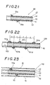
- Fig. 21 is a sectional view of a metal gasket 90 of Embodiment 3-6, in which the cross-sectional configuration of surface pressure generating materials 91a and 91b is not circular but triangular.
- the bending stress that acts on the base 10 concentrates more than in the case of surface pressure generating materials having a circular cross-sectional configuration. Therefore, the surface pressure acts somewhat stronger than in the case of surface pressure materials having a circular cross-sectional configuration.
- Fig. 22 shows a metal gasket 100 of Embodiment 3-7.
- a plurality of surface pressure generating materials 101a, 101b, 101c, 101d and 101e are disposed successively in the mentioned order from a bore 102 toward the outer periphery thereof.
- This embodiment may be employed, for example, in a case where a high-pressure gas is sealed with flanges having a relatively large diameter.
- the radial distance between the surface pressure generating materials 101a and 101b as viewed from the center of the bore 102 is l 1
- the radial distance between the surface pressure generating materials lOlb and 101c is l 2
- those between the surface pressure generating materials 101c and 101d and the surface pressure generating materials 101d and 10le are 1 3 and l 4 , respectively.
- the relationship between these distances is preferably set so as to be l 1 ⁇ l 2 ⁇ l 3 ⁇ l 4 .
- the principle of the surface pressure distribution is as described above. This embodiment is most suitable when bolts are located at the outer periphery of the surface pressure generating material 101e.
- Fig. 23 shows a metal gasket 110 of Embodiment 3-8.
- a subsidiary plate 15 which is similar to that employed in Embodiment 1-6 is disposed over either one or each of the sides with either one or both of the surface pressure generating materials llla and lllb interposed therebetween.
- This embodiment may be used for, for example, sealing of flanges which have large thermal deformation and long dimensions.
- a subsidiary plate 15 is provided for one of the sides which is closer to a flange which moves more than the other, or for each side, thereby preventing the surface pressure generating materials llla and lllb from being scraped off.
- the present invention may be applied not only to cylinder gaskets for engines but also to flange joints and cylinder heads of air compressors, for example.
- the present invention may be employed not only for gas seal but also for sealing liquids.
Landscapes
- Engineering & Computer Science (AREA)
- General Engineering & Computer Science (AREA)
- Mechanical Engineering (AREA)
- Gasket Seals (AREA)
Abstract
Applications Claiming Priority (5)
| Application Number | Priority Date | Filing Date | Title |
|---|---|---|---|
| JP63128476A JP2568886B2 (ja) | 1988-05-27 | 1988-05-27 | 金属ガスケット |
| JP128476/88 | 1988-05-27 | ||
| JP104730/89 | 1989-04-26 | ||
| JP1104730A JP2785955B2 (ja) | 1989-04-26 | 1989-04-26 | 金属ガスケット |
| PCT/JP1989/000528 WO1989011607A1 (fr) | 1988-05-27 | 1989-05-26 | Joint metallique d'etancheite |
Publications (3)
| Publication Number | Publication Date |
|---|---|
| EP0369033A1 true EP0369033A1 (fr) | 1990-05-23 |
| EP0369033A4 EP0369033A4 (en) | 1992-08-05 |
| EP0369033B1 EP0369033B1 (fr) | 1995-11-15 |
Family
ID=26445134
Family Applications (1)
| Application Number | Title | Priority Date | Filing Date |
|---|---|---|---|
| EP89906428A Expired - Lifetime EP0369033B1 (fr) | 1988-05-27 | 1989-05-26 | Joint metallique d'etancheite |
Country Status (5)
| Country | Link |
|---|---|
| US (1) | US5322299A (fr) |
| EP (1) | EP0369033B1 (fr) |
| KR (1) | KR920700368A (fr) |
| DE (1) | DE68924832T2 (fr) |
| WO (1) | WO1989011607A1 (fr) |
Cited By (9)
| Publication number | Priority date | Publication date | Assignee | Title |
|---|---|---|---|---|
| EP0468526A1 (fr) * | 1990-07-26 | 1992-01-29 | Taiho Kogyo Co., Ltd. | Joint métallique |
| FR2717243A1 (fr) * | 1994-03-11 | 1995-09-15 | Curty Payen Sa | Joint d'étanchéité plat. |
| DE19528031A1 (de) * | 1995-07-31 | 1997-02-06 | Krebsoege Sinterholding Gmbh | Flachdichtung aus Metall |
| WO2005017395A1 (fr) * | 2003-08-16 | 2005-02-24 | Federal-Mogul Sealing Systems Gmbh | Garniture metallique plate |
| EP1619425A1 (fr) * | 2004-07-23 | 2006-01-25 | Ishikawa Gasket Co. Ltd. | Joint d'étanchéité métallique |
| US7055830B2 (en) | 2003-12-19 | 2006-06-06 | Ishikawa Gasket Co., Ltd. | Metal laminate gasket |
| CN103635724A (zh) * | 2011-07-11 | 2014-03-12 | Nok株式会社 | 利用金属衬垫的密封构造 |
| CN105829781A (zh) * | 2013-12-18 | 2016-08-03 | Nok株式会社 | 气缸盖衬垫及其制造方法 |
| WO2020028605A1 (fr) * | 2018-08-01 | 2020-02-06 | Federal-Mogul Motorpart S Llc | Ensemble joint d'étanchéité auto-formant et procédés de construction et d'assemblage de celui-ci |
Families Citing this family (47)
| Publication number | Priority date | Publication date | Assignee | Title |
|---|---|---|---|---|
| US5391887A (en) * | 1993-02-10 | 1995-02-21 | Trustees Of Princeton University | Method and apparatus for the management of hazardous waste material |
| GB2290586B (en) * | 1994-06-15 | 1997-08-13 | T & N Technology Ltd | Beads for gaskets |
| US5615898A (en) * | 1995-08-15 | 1997-04-01 | Clark; James M. | Bead seal motorcycle gasket |
| US5700015A (en) * | 1996-09-26 | 1997-12-23 | Dana Corporation | Rubber/metal combustion seal |
| US6105968A (en) * | 1997-02-24 | 2000-08-22 | Massachusetts Institute Of Technology | Textured seal for reduced wear |
| US6318733B1 (en) * | 1997-09-05 | 2001-11-20 | Ishikawa Gasket Co., Ltd | Metal laminate gasket with elastic auxiliary sealing member |
| FR2768211B1 (fr) * | 1997-09-09 | 1999-10-22 | Curty Payen Sa | Joint statique d'etancheite |
| US6073938A (en) * | 1997-11-06 | 2000-06-13 | Kokusan Parts Industry Co., Ltd. | Sealing structure |
| AU2537199A (en) * | 1998-03-10 | 1999-09-27 | Federal-Mogul Technology Limited | Gasket coating |
| US6113109A (en) * | 1998-04-20 | 2000-09-05 | Fel-Pro Incorporated | Expanded graphite gasket with beaded stress risers |
| JP4404393B2 (ja) * | 1998-11-13 | 2010-01-27 | 日本ガスケット株式会社 | ガスケット |
| US6619664B1 (en) | 1998-12-18 | 2003-09-16 | Caterpillar Inc | Wear improvement to textured lip seal |
| DE19939869A1 (de) * | 1999-08-23 | 2001-04-12 | Elringklinger Gmbh | Flachdichtung |
| FR2805036B1 (fr) * | 2000-02-10 | 2002-06-14 | Valeo Thermique Moteur Sa | Echangeur de chaleur avec joint d'etancheite ameliore, en particulier pour vehicule automobile |
| DE10048871A1 (de) * | 2000-07-14 | 2002-03-14 | Freudenberg Carl | Flachdichtung |
| JP3547417B2 (ja) * | 2001-10-23 | 2004-07-28 | 石川ガスケット株式会社 | メタルガスケット |
| WO2004025148A1 (fr) * | 2002-09-12 | 2004-03-25 | Nok Corporation | Joint statique |
| DE10247559A1 (de) * | 2002-10-11 | 2004-05-13 | Federal-Mogul Sealing Systems Bretten Gmbh & Co. Kg | Dichtelement |
| US6779801B2 (en) * | 2002-10-21 | 2004-08-24 | Dana Corporation | Anti-fret primer for multilayer gaskets |
| US6848690B1 (en) * | 2002-11-19 | 2005-02-01 | Ryan Hunter | Seal for head gaskets of internal combustion engines |
| JP2004245252A (ja) * | 2003-02-12 | 2004-09-02 | Uchiyama Mfg Corp | エンコーダ付密封装置 |
| AU2003900862A0 (en) * | 2003-02-26 | 2003-03-13 | The University Of Sydney | Improved sealing arrangement for use in evacuating a glass chamber |
| US7048279B2 (en) * | 2003-05-20 | 2006-05-23 | Federal-Mogul World Wide, Inc. | Laminated carrier gasket with off-set elastomeric sealing |
| US20050012279A1 (en) * | 2003-07-15 | 2005-01-20 | Hodges James W. | Gasket having an inner edge with coined angles and method of manufacture |
| WO2005052414A2 (fr) * | 2003-11-25 | 2005-06-09 | Garlock Sealing Technologies, Llc | Zone centrale de joint d'etancheite ondulee presentant une surface profilee |
| DE102004014869B4 (de) * | 2004-03-26 | 2010-04-01 | Federal-Mogul Sealing Systems Gmbh | Flachdichtung |
| DE102004034824B4 (de) * | 2004-07-19 | 2006-10-05 | Reinz-Dichtungs-Gmbh | Metallische Flachdichtung |
| US20070262534A1 (en) * | 2004-08-12 | 2007-11-15 | Ryan Hunter | Head gasket for internal combustion engines |
| US7070187B2 (en) * | 2004-11-09 | 2006-07-04 | Federal-Mogul World Wide, Inc | Gasket assembly |
| US20060197289A1 (en) * | 2005-03-07 | 2006-09-07 | Basso Industry Corp. | Air-sealing apparatus for a pneumatic tool |
| US20060237463A1 (en) * | 2005-04-21 | 2006-10-26 | Tony Riviezzo | Component seal for plastic tanks |
| US7655126B2 (en) * | 2006-03-27 | 2010-02-02 | Federal Mogul World Wide, Inc. | Fabrication of topical stopper on MLS gasket by active matrix electrochemical deposition |
| US7866670B2 (en) * | 2006-11-08 | 2011-01-11 | Federal-Mogul World Wide, Inc. | Static gasket |
| US20080143060A1 (en) * | 2006-12-15 | 2008-06-19 | Arvid Casler | Multi-layer gasket |
| JP4361096B2 (ja) * | 2007-01-05 | 2009-11-11 | 石川ガスケット株式会社 | 金属製ガスケット |
| WO2010084597A1 (fr) * | 2009-01-23 | 2010-07-29 | トヨタ自動車株式会社 | Structure étanche |
| US8579299B2 (en) * | 2009-04-03 | 2013-11-12 | Interface Solutions, Inc. | Gasket having adhesive element |
| DE102009053238B4 (de) * | 2009-11-13 | 2012-06-21 | Continental Automotive Gmbh | Turboladergehäuse mit einer Dichtungseinrichtung |
| DE102010062749A1 (de) * | 2010-12-09 | 2012-06-14 | Continental Automotive Gmbh | Turbolader, der in den Zylinderkopf eines Motors integriert ist. |
| DE102012109646A1 (de) * | 2012-10-10 | 2014-04-10 | Elringklinger Ag | Zylinderkopfdichtung |
| DE102013219300A1 (de) * | 2013-09-25 | 2015-03-26 | Elringklinger Ag | Zwischenplatte und Steuereinheit |
| DE102013219295A1 (de) | 2013-09-25 | 2015-03-26 | Elringklinger Ag | Zwischenplatte |
| JP6439161B1 (ja) * | 2018-03-19 | 2018-12-19 | 国産部品工業株式会社 | 金属製ガスケット |
| US11971392B2 (en) * | 2019-06-25 | 2024-04-30 | Wyatt Technology, Llc | Sealing structure for a field flow fractionator |
| DE102020121081A1 (de) * | 2020-08-11 | 2022-02-17 | Seg Automotive Germany Gmbh | Starter für eine Brennkraftmaschine und Verfahren zu dessen Herstellung |
| US11773978B2 (en) * | 2021-03-11 | 2023-10-03 | Dana Automotive Systems Group, Llc | Wire ring combustion seal for automotive engine |
| DE102023121475A1 (de) * | 2023-08-10 | 2025-02-13 | Elringklinger Ag | Dichtungselement und Dichtungsanordnung |
Family Cites Families (32)
| Publication number | Priority date | Publication date | Assignee | Title |
|---|---|---|---|---|
| US1851948A (en) * | 1927-03-31 | 1932-03-29 | Frigidaire Corp | Gasket |
| GB710392A (en) * | 1952-06-23 | 1954-06-09 | William Arthur Meyrick Lloyd G | Improvements in gaskets and like packing devices |
| DE1104775B (de) * | 1959-12-04 | 1961-04-13 | Goetzewerke | Dichtungsring |
| GB1051747A (fr) * | 1964-08-28 | |||
| JPS4912513Y1 (fr) * | 1967-04-24 | 1974-03-27 | ||
| US3473813A (en) * | 1967-07-05 | 1969-10-21 | Gen Motors Corp | Cylinder head gasket |
| GB1268633A (en) * | 1968-04-05 | 1972-03-29 | Robert Ford | Improvements in or relating to gaskets |
| US3737169A (en) * | 1971-05-13 | 1973-06-05 | Federal Mogul Corp | Gasket material and method of making same |
| JPS5221767B2 (fr) * | 1972-05-17 | 1977-06-13 | ||
| US3909019A (en) * | 1972-06-14 | 1975-09-30 | Toma D Leko | Gaskets |
| CA977382A (en) * | 1973-03-26 | 1975-11-04 | Terence P. Nicholson | Control plate/gasket arrangements |
| JPS51139859U (fr) * | 1975-05-06 | 1976-11-11 | ||
| JPS51139859A (en) * | 1975-05-29 | 1976-12-02 | Ono Sangyo Kk | Method of producing cases |
| US4140323A (en) * | 1977-09-12 | 1979-02-20 | Felt Products Mfg. Co. | Embossed gasket |
| US4272085A (en) * | 1978-10-07 | 1981-06-09 | Kawasaki Jukogyo Kabushiki Kaisha | Cylinder head gasket for a liquid cooled internal combustion engine |
| JPS5838194Y2 (ja) * | 1979-04-24 | 1983-08-29 | 日本メタルガスケット株式会社 | ガスケツト |
| US4428593A (en) * | 1981-07-10 | 1984-01-31 | Felt Products Mfg. Co. | Gasket assembly having improved sealing characteristics and method of making same |
| JPS5838194A (ja) * | 1981-09-01 | 1983-03-05 | 有限会社研究所アイエス | しおり |
| JPS6060370A (ja) * | 1983-08-27 | 1985-04-06 | ツア−ンラトフアブリク フリ−トリツヒシヤフエン アクチエンゲゼルシヤフト | パツキング装置 |
| US4653507A (en) * | 1983-09-30 | 1987-03-31 | Pfizer Inc. | Differential thermal testing apparatus and method |
| JPS6092745U (ja) * | 1983-11-30 | 1985-06-25 | 日野自動車株式会社 | ソフトラミネ−ト型シリンダヘツドガスケツト |
| JPH0612095B2 (ja) * | 1985-05-09 | 1994-02-16 | 日本メタルガスケット株式会社 | 単板金属ガスケット |
| DE3523151A1 (de) * | 1985-06-28 | 1987-01-08 | Goetze Ag | Weichstoffflachdichtung |
| US4625979A (en) * | 1985-08-05 | 1986-12-02 | Felt Products Mfg. Co. | Seal assembly having a low extrusion resistant elastomeric sealing bead |
| JPS62155375A (ja) * | 1985-12-27 | 1987-07-10 | Nippon Metal Gasket Kk | 金属ガスケツト |
| JPS62261757A (ja) * | 1986-04-22 | 1987-11-13 | Mazda Motor Corp | 金属ガスケツト |
| JPS62261755A (ja) * | 1986-04-22 | 1987-11-13 | Mazda Motor Corp | 金属ガスケツト |
| JPH0625598B2 (ja) * | 1986-05-26 | 1994-04-06 | 石川ガスケット株式会社 | 面圧調整片付金属積層形ガスケット |
| JPS63112261A (ja) * | 1986-10-31 | 1988-05-17 | 東京都 | 手引き式運搬車輌 |
| JPS63149479A (ja) * | 1986-12-12 | 1988-06-22 | Nippon Metal Gasket Kk | 単板金属ガスケツト |
| JPH0524864Y2 (fr) * | 1987-01-14 | 1993-06-23 | ||
| US4743421A (en) * | 1987-04-20 | 1988-05-10 | Fel-Pro Incorporated | Method of making gasket having roller coated secondary seals |
-
1989
- 1989-05-26 EP EP89906428A patent/EP0369033B1/fr not_active Expired - Lifetime
- 1989-05-26 DE DE68924832T patent/DE68924832T2/de not_active Expired - Fee Related
- 1989-05-26 WO PCT/JP1989/000528 patent/WO1989011607A1/fr not_active Ceased
- 1989-05-26 KR KR1019890702156A patent/KR920700368A/ko not_active Ceased
-
1993
- 1993-09-30 US US08/132,155 patent/US5322299A/en not_active Expired - Fee Related
Non-Patent Citations (1)
| Title |
|---|
| See references of WO8911607A1 * |
Cited By (20)
| Publication number | Priority date | Publication date | Assignee | Title |
|---|---|---|---|---|
| EP0468526A1 (fr) * | 1990-07-26 | 1992-01-29 | Taiho Kogyo Co., Ltd. | Joint métallique |
| US5332237A (en) * | 1990-07-26 | 1994-07-26 | Taiho Kogyo Co., Ltd. | Metal gasket with welded shim |
| US5385354A (en) * | 1990-07-26 | 1995-01-31 | Taiho Kogyo Co., Ltd. | Metal gasket |
| US5393076A (en) * | 1990-07-26 | 1995-02-28 | Taiho Kogyo Co., Ltd. | Metal gasket with base plate having coatings of diverse thicknesses |
| US5472217A (en) * | 1990-07-26 | 1995-12-05 | Taiho Kogyo Co., Ltd. | Metal gasket |
| FR2717243A1 (fr) * | 1994-03-11 | 1995-09-15 | Curty Payen Sa | Joint d'étanchéité plat. |
| DE19528031A1 (de) * | 1995-07-31 | 1997-02-06 | Krebsoege Sinterholding Gmbh | Flachdichtung aus Metall |
| EP0757195B1 (fr) * | 1995-07-31 | 2000-06-07 | Federal-Mogul Sealing Systems GmbH | Méthode de fabrication d'un joint plat métallique |
| WO2005017395A1 (fr) * | 2003-08-16 | 2005-02-24 | Federal-Mogul Sealing Systems Gmbh | Garniture metallique plate |
| US7055830B2 (en) | 2003-12-19 | 2006-06-06 | Ishikawa Gasket Co., Ltd. | Metal laminate gasket |
| EP1619425A1 (fr) * | 2004-07-23 | 2006-01-25 | Ishikawa Gasket Co. Ltd. | Joint d'étanchéité métallique |
| CN103635724A (zh) * | 2011-07-11 | 2014-03-12 | Nok株式会社 | 利用金属衬垫的密封构造 |
| US9726290B2 (en) | 2011-07-11 | 2017-08-08 | Nok Corporation | Seal structure using metal gasket |
| CN105829781A (zh) * | 2013-12-18 | 2016-08-03 | Nok株式会社 | 气缸盖衬垫及其制造方法 |
| EP3086004A4 (fr) * | 2013-12-18 | 2016-11-23 | Nok Corp | Joint de culasse et son procédé de fabrication |
| US10184424B2 (en) | 2013-12-18 | 2019-01-22 | Nok Corporation | Cylinder head gasket and method of manufacturing the same |
| CN105829781B (zh) * | 2013-12-18 | 2019-02-12 | Nok株式会社 | 气缸盖衬垫及其制造方法 |
| WO2020028605A1 (fr) * | 2018-08-01 | 2020-02-06 | Federal-Mogul Motorpart S Llc | Ensemble joint d'étanchéité auto-formant et procédés de construction et d'assemblage de celui-ci |
| CN112703340A (zh) * | 2018-08-01 | 2021-04-23 | 费德罗-莫格尔汽车零部件有限责任公司 | 自成型垫圈组件及其制造方法和组装方法 |
| US12416359B2 (en) | 2018-08-01 | 2025-09-16 | Federal-Mogul Motorparts Llc | Self-forming gasket assembly and methods of construction and assembly thereof |
Also Published As
| Publication number | Publication date |
|---|---|
| KR920700368A (ko) | 1992-02-19 |
| EP0369033B1 (fr) | 1995-11-15 |
| EP0369033A4 (en) | 1992-08-05 |
| DE68924832D1 (de) | 1995-12-21 |
| US5322299A (en) | 1994-06-21 |
| WO1989011607A1 (fr) | 1989-11-30 |
| DE68924832T2 (de) | 1996-04-18 |
Similar Documents
| Publication | Publication Date | Title |
|---|---|---|
| EP0369033A1 (fr) | Joint metallique d'etancheite | |
| EP0574166B1 (fr) | Garniture métallique | |
| US6036194A (en) | Combustion gas seal for an internal combustion engine | |
| EP0533357A1 (fr) | Joint d'étanchéité métallique | |
| KR100589715B1 (ko) | 금속 개스킷 | |
| US6076833A (en) | Metal gasket | |
| US5580065A (en) | Metallic gasket with inwardly projecting folded end portion | |
| US7665741B2 (en) | Laminate-type gasket | |
| US6135459A (en) | Metal gasket | |
| EP1857717B1 (fr) | Joint de culasse d'un cylindre | |
| US5921558A (en) | High recovery combustion seal gasket | |
| US4852893A (en) | Elastomeric coated perforated metal core composite gasket and method of making same | |
| JP2002054743A (ja) | ヘッドガスケット | |
| JP2579175B2 (ja) | 金属ガスケット | |
| EP1510734B1 (fr) | Joint d'étanchéité avec butée flexible | |
| US6981703B2 (en) | Cylinder head gasket | |
| JPH01299366A (ja) | 金属ガスケット | |
| EP1528299B1 (fr) | Joint métallique lamellé | |
| JP3314371B2 (ja) | 金属ガスケット | |
| JP2785955B2 (ja) | 金属ガスケット | |
| JPH0656210B2 (ja) | 金属ガスケット | |
| CN1207164A (zh) | 内燃机的燃气密封装置 | |
| JPH051731Y2 (fr) | ||
| US6997462B2 (en) | Cylinder head gasket | |
| KR20020012485A (ko) | 헤드 개스킷 |
Legal Events
| Date | Code | Title | Description |
|---|---|---|---|
| PUAI | Public reference made under article 153(3) epc to a published international application that has entered the european phase |
Free format text: ORIGINAL CODE: 0009012 |
|
| 17P | Request for examination filed |
Effective date: 19900214 |
|
| AK | Designated contracting states |
Kind code of ref document: A1 Designated state(s): DE FR GB IT |
|
| A4 | Supplementary search report drawn up and despatched |
Effective date: 19920616 |
|
| AK | Designated contracting states |
Kind code of ref document: A4 Designated state(s): DE FR GB IT |
|
| 17Q | First examination report despatched |
Effective date: 19940204 |
|
| GRAA | (expected) grant |
Free format text: ORIGINAL CODE: 0009210 |
|
| AK | Designated contracting states |
Kind code of ref document: B1 Designated state(s): DE FR GB IT |
|
| REF | Corresponds to: |
Ref document number: 68924832 Country of ref document: DE Date of ref document: 19951221 |
|
| ITF | It: translation for a ep patent filed | ||
| PLBI | Opposition filed |
Free format text: ORIGINAL CODE: 0009260 |
|
| PLBQ | Unpublished change to opponent data |
Free format text: ORIGINAL CODE: EPIDOS OPPO |
|
| ET | Fr: translation filed | ||
| 26 | Opposition filed |
Opponent name: T&N HOLDINGS GMBH Effective date: 19960313 |
|
| PLBF | Reply of patent proprietor to notice(s) of opposition |
Free format text: ORIGINAL CODE: EPIDOS OBSO |
|
| PLBF | Reply of patent proprietor to notice(s) of opposition |
Free format text: ORIGINAL CODE: EPIDOS OBSO |
|
| PLBO | Opposition rejected |
Free format text: ORIGINAL CODE: EPIDOS REJO |
|
| PLBN | Opposition rejected |
Free format text: ORIGINAL CODE: 0009273 |
|
| STAA | Information on the status of an ep patent application or granted ep patent |
Free format text: STATUS: OPPOSITION REJECTED |
|
| 27O | Opposition rejected |
Effective date: 19970927 |
|
| PGFP | Annual fee paid to national office [announced via postgrant information from national office to epo] |
Ref country code: GB Payment date: 20010515 Year of fee payment: 13 |
|
| PGFP | Annual fee paid to national office [announced via postgrant information from national office to epo] |
Ref country code: FR Payment date: 20010530 Year of fee payment: 13 |
|
| REG | Reference to a national code |
Ref country code: GB Ref legal event code: IF02 |
|
| PG25 | Lapsed in a contracting state [announced via postgrant information from national office to epo] |
Ref country code: GB Free format text: LAPSE BECAUSE OF NON-PAYMENT OF DUE FEES Effective date: 20020526 |
|
| PGFP | Annual fee paid to national office [announced via postgrant information from national office to epo] |
Ref country code: DE Payment date: 20020527 Year of fee payment: 14 |
|
| GBPC | Gb: european patent ceased through non-payment of renewal fee |
Effective date: 20020526 |
|
| PG25 | Lapsed in a contracting state [announced via postgrant information from national office to epo] |
Ref country code: FR Free format text: LAPSE BECAUSE OF NON-PAYMENT OF DUE FEES Effective date: 20030131 |
|
| REG | Reference to a national code |
Ref country code: FR Ref legal event code: ST |
|
| PG25 | Lapsed in a contracting state [announced via postgrant information from national office to epo] |
Ref country code: DE Free format text: LAPSE BECAUSE OF NON-PAYMENT OF DUE FEES Effective date: 20031202 |
|
| PG25 | Lapsed in a contracting state [announced via postgrant information from national office to epo] |
Ref country code: IT Free format text: LAPSE BECAUSE OF NON-PAYMENT OF DUE FEES;WARNING: LAPSES OF ITALIAN PATENTS WITH EFFECTIVE DATE BEFORE 2007 MAY HAVE OCCURRED AT ANY TIME BEFORE 2007. THE CORRECT EFFECTIVE DATE MAY BE DIFFERENT FROM THE ONE RECORDED. Effective date: 20050526 |