EP0369525B1 - Procédé de production d'une texture à armure de gaze - Google Patents
Procédé de production d'une texture à armure de gaze Download PDFInfo
- Publication number
- EP0369525B1 EP0369525B1 EP89202828A EP89202828A EP0369525B1 EP 0369525 B1 EP0369525 B1 EP 0369525B1 EP 89202828 A EP89202828 A EP 89202828A EP 89202828 A EP89202828 A EP 89202828A EP 0369525 B1 EP0369525 B1 EP 0369525B1
- Authority
- EP
- European Patent Office
- Prior art keywords
- plane
- thread
- stationary
- crossing
- line segment
- Prior art date
- Legal status (The legal status is an assumption and is not a legal conclusion. Google has not performed a legal analysis and makes no representation as to the accuracy of the status listed.)
- Expired - Lifetime
Links
Images




Classifications
-
- D—TEXTILES; PAPER
- D03—WEAVING
- D03C—SHEDDING MECHANISMS; PATTERN CARDS OR CHAINS; PUNCHING OF CARDS; DESIGNING PATTERNS
- D03C7/00—Leno or similar shedding mechanisms
- D03C7/06—Mechanisms having eyed needles for moving warp threads from side to side of other warp threads
Definitions
- the present invention relates to a method for producing a leno or cross weaving texture.
- Some methods belonging to a first type take advantage of the successive and alternate tensioning and releasing of two warp threads moving to both sides of another warp thread -- called "stationary-thread" --, slidingly connected with each other, so as to cause the crossing-thread(s) to shift to the one or to the other sides of the stationary-thread, with the desired textile effect of crossing of the crossing-thread(s) with the stationary-thread being consequently achieved.
- a method of a second type exploits, on the contrary, the combined action of a set of special heddles -- called "English leno or crossing weaving units" -- in order to obtain the successive crossing of the stationary-thread and of the crossing-thread for generating the leno or cross weaving texture.
- a set of special heddles called "English leno or crossing weaving units" -- in order to obtain the successive crossing of the stationary-thread and of the crossing-thread for generating the leno or cross weaving texture.
- the first type of methods some of which enable the speeds rendered possible by the modern needle weaving planes (more than 2,000 weft insertions per minute) to be fully exploited, mandatorily require that mechanisms be provided which make it possible some warp threads to be successively tensioned and released, with said warp threads undergoing strong stretches, and rendering more complex the initial threading of the threads through the same weaving plane.
- the purpose of the present invention is that of providing a solution for overcoming the limitations which affect the above said methods known from the prior art, and specifically the method known from EP-A-0 253 451, thus making it possible the actual capabilities of the modern weaving planes to be fully taken advantage of, while simultaneously simplifying their threading system and offering a high flexibility of realization.
- the line segment can be composed by any portions of at least one thread constituted by either natural or artificial fibres, which is destined to become a part of the fabric which is being formed, and is used for the specific function of realizing the shift of the crossing-thread from either side to the other side of the stationary-thread(s), by being moved in a per se known way by two healds situated on opposite sides relatively to said stationary-thread(s).
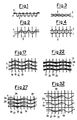
- Figure 1 relevant to the warp profile, shows the non-essential feature of the stationary-thread remaining always on one side relatively to the weft, indicated by the reference numeral 3 in its various insertions, around which, on the contrary, the crossing-thread 2 gets interlaced.
- Figures 3 and 4 show how the stationary-thread 1 and the crossing-thread 2 get arranged in practice owing to the effects of the tensions and of the natural flexibility of the threads which constitute the textile interlacement. From these figures, one will easily see that the definition of "crossing-thread” and “stationary-thread” loses its ground for being once that both of said threads.have been incorporated in the fabric, in that, as said Figures precisely show, in the finished fabric they cannot be any longer distinguished from each other.
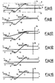
- Figure 5 and, in plan view, also Figure 6, show a first step of a first example of practical embodiment of the method according to the present invention in order to cross two warp threads, i.e., a crossing-thread 4 and a stationary-thread 7, with each other.
- the crossing-thread 4 is, threaded through the hole of a first heald 5, in the top position of a shed 6, whilst the stationary-thread 7 is in the opposite position, threaded first through the hole of a second heald 8 and then through the hole of a third heald 9 having a particular shape.
- the third heald 9 in this particular form of practical embodiment of the present invention, is provided with an arm 9a extending from it and along a short distance parallel to it, so as to define a gap 11.
- a length, or a portion 10, of the stationary thread 7, running between the threading holes of the two healds 8 and 9 which move it, constitutes a line segment.
- Said line segment 10 can be inclined, so as to cross a weaving plane, indicated by the character "C" in Figure 5, alternatively on the one and on the opposite side of the same weaving plane C, which is defined as the plane on which the fabric is formed,
- the inclined line segment 10 is such as to cause the crossing-thread 4 to alternatively shift to both sides of the stationary-thread 7.
- the inclination of the length, or line segment 10, of the stationary-thread 7 is such as to move the crossing-thread 4 to run, during its subsequent movement in order to come to the opposite position of the shed 6, along the surface of the segment 10, until said crossing-thread 4 enters the gap provided on the third heald 9.
- the line segment constituted by the segment 10 of the stationary thread 7 connects two planes, or two sets of planes, one only of these planes of the respective sets being indicated in chain line at A and B, these planes being perpendicular to the weaving plane C and laying parallel to the stationary-thread 7, on both sides of this latter.
- a beating reed 12 beats then a weft insertion 13, up to bring it to rest against the weft insertions already inserted in the fabric, before the healds 5,8 and 9 are moved in order to invert the positions of the threads in the shed 6.
- Figure 7 and the respective plan view of Figure 8 show an intermediate time point, in which the shed 6 is practically closed, between the steps of the preceding Figures 5 and 6 and the step depicted in following Figures 9 and 10.
- the crossing-thread 4 has ended its sliding, and has entered the gap 11 of the third heald 9, thus getting shifted and coming to lay on a plane A perpendicular to the weaving plane C and parallel to the stationary-thread 7, but on the opposite side relatively to the side on which it was during the initial step shown in Figures 5 and 6, when it was lying on one plane from the set of planes B.
- Figures 13 and 14 show an intermediate step between the step shown by Figures 11 and 12, and the step shown by the subsequent Figures 15 and 16.
- the crossing-thread 4 is not deviated now, during its movement of shifting towards the opposite side of the shed 6, by the inclined segment 10 of the stationary-thread 4.
- Such a stationary-thread segment 10, with the herein shown inclination enables hence said crossing-thread 4 to simply completely move on a plane B perpendicular to the weaving plane C, without any motion components parallel to said weaving plane C, but it does not constitute, in this step of this particular form of practical embodiment of the present invention, a sliding line which may cause the crossing-thread 4 to shift parallelly to the weaving plane C.
- Figure 17 a schematic view can be seen of a portion of a leno or cross weaving texture, manufactured according to the exemplifying form of practical embodiment of the method proposed by the present invention, as disclosed by the Figures from 5 to 16.
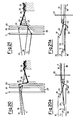
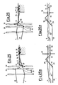
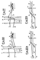
- Figures from 18 to 22 and from 18a to 22a show another possible exemplifying form of a practical embodiment of the method proposed according to the present invention, in which for same components same reference numerals are used, and in which two warp threads 17 and 18 are provided, which are destined to act as stationary-threads.
- the line segment which can be inclined in order to cause the crossing-thread 4 to slide during its movement of shifting to the one, or to the other one, of the sides of the two stationary-threads 17 and 18, is actually constituted by respective different line segments 21 and 22 of the two different stationary threads 17 and 18.
- the crossing-thread 4 moved by the corresponding heald 5 is in the top position of the shed 6 and before going to the fabric being formed, runs above a first weft insertion 24, through a "V" region formed by the two segments 21 and 22 of the stationary threads 17 and respectively 18.
- each one of the lifted healds 19 and 20 relatively to the further, lowered, heald 23 determines the inclinations of both segments 21 and 22 of the stationary-threads 17 and 18 which, in their turn, cause the shifting of the crossing-thread 4 to the one side and to the other side of the further heald 23, and therefore of the stationary-threads 17 and 18 coming together into the hole of the heald 23, and exiting it on opposite sides.
- the movement of the further heald 23 is decided on the basis of the desired textile interlacement between the weft insertions 24 and the stationary-threads 17 and 18.
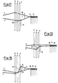
- the crossing-thread 4 by getting crossed with the metal blade 34, is obliged to form loop portions, or loops, 39, around it, which loops are of size and shape corresponding to those of the cross-section of the metal blade 34 so that, as the fabric gets disengaged from the metal blade 34, only the loops remain, which loops precisely protrude outwards from the fabric with a stationary-thread 28 being arranged inside them. More precisely, the line segment for keeping portions of the crossing-thread 4 raised, is positioned at at least one portion of the stationary-thread 28 and indicated by the reference numeral 31, and under the thread 4.
- the crossing-thread 4 is in the bottom position of the shed 6, looking at the figure, and is before the metal blade 34 and the stationary-thread 28 positioned above a weft insertion 35.
- a portion, or line segment, 31 of the stationary thread 28, thanks to the lowered position of a heald 29 and to the simultaneously lifted position of a heald 30, is inclined towards a plane B on the side of the heald 29.
- the stationary-thread 28 runs through the holes of such healds 29 and 30 before also running through the hole 33 of the metal blade 34 which returns it back to a stable position, parallel to the weaving plane C, alongside of the same metal blade 34.
- the crossing-thread 4 After a weft insertion 37, in Figures 26 and 26a, the crossing-thread 4 returns back to its top position, with the healds 29 and 30 which control the stationary-thread 28 simultaneously inverting again their position, so that the inclination of the segment 31 will be now in the suitable direction for a further crossing to be caused to occur between the stationary-thread 28 and the crossing-thread 4.
- the weaving method called "gauze weaving” has in fact been used here for the only purpose of creating the loops 39 thanks to the crossing of the crossing-thread 4 which constitutes them, with the metal blade 34 replacing, at least for a certain length inside the fabric, the stationary-thread.
- Such a method is essentially characterized by the use of one or more line segments which can be alternatively inclined towards the one side, or towards the other side, of the at least one stationary-thread provided, and constituted by lengths of warp threads on whose surface the crossing-thread is caused to slide, thus being alternatively shifted, owing to the effect of such different inclinations, to the one side and to the other side of the same at least one stationary-thread: only thanks to such one or more inclined sliding length(s) the possibility is given of accomplishing the gauze interlacement in all of its possible and imaginable variants, due to the function performed by these lengths, of causing the crossing-thread, according to presettable sequential cycles, to slide to opposite regions of the shed, and to opposite half-weaving planes relatively to the stationary-thread.
- the same at least one inclined sliding length can be accomplished, and/or thought of, in several ways and positions.
- the essential characteristic thereof is that it should perform the hereinabove illustrated functions in order that the leno or cross weaving texture can be obtained by means of the sliding which said inclined length will cause the crossing-thread to undergo, in order that said crossing-thread is brought to cross with the stationary-thread.
- the stationary-thread can be accompanied by other warp threads, with each of said threads performing its independent movements in its own shed and perpendicularly to the weaving plane: the crossing-thread will perform its movements getting crossed with this set of warp threads.
Landscapes
- Engineering & Computer Science (AREA)
- Textile Engineering (AREA)
- Looms (AREA)
- Treatments For Attaching Organic Compounds To Fibrous Goods (AREA)
- Woven Fabrics (AREA)
- Adornments (AREA)
- Knitting Of Fabric (AREA)
Claims (5)
- Procédé de production d'un tissu de gaze ou d'une texture à chaîne croisée, selon lequel en alternance avec des insertions de trâme successives (13-16; 24-27; 35-38; 40-43), un fil de chaîne de croisement (4) croise au moins un fil de chaîne "fixe" (7;17,18;28) alternativement à partir d'un côté dudit au moins un fil de chaîne "fixe (7;17,18;28) jusqu'à son côté opposé et vice et versa, selon lequel ledit fil de chaîne de croisement (4) est déplacé dans le sens transversal par rapport au plan (C) de la texture de tissage et dans le sens perpendiculaire vers le haut et vers le bas par rapport au plan (C) de la texture de tissage, tandis qu'au moins ledit fil de chaîne "fixe" (7,17,18,28) ne peut se déplacer que dans un plan perpendiculaire vers le haut et vers le bas par rapport au plan (C) de la texture de tissage, ledit procédé étant caractérisé en ce que:- un segment de ligne (10;21,22;31) dudit au moins un fil de chaîne "fixe" (7;17,18;28) est incliné et est amené à s'étendre, en amont du peigne (12, fig 5) et dans la zone de la lice, entre deux plans imaginaires (A, B, fig 6) parallèles l'un par rapport à l'autre et perpendiculaires au plan (C) de la texture de tissage, un (A) desdits deux plans se situant sur un côté dudit fil "fixe" (7;17,18;28), l'autre (B) desdits deux plans se situant sur le côté opposé dudit fil "fixe" (7;17,18;28),- ledit segment de ligne (10;21,22;31) étant amené à croiser le plan (C) de la texture de tissage en alternance à partir d'une position située au-dessus du plan (C) de la texture de tissage et proche dudit autre plan (B) vers une position située en-dessous du plan (C) de la texture de tissage et proche dudit plan (A) et à partir d'une position située en-dessous du plan (C) de la texture de tissage et à proximité dudit autre plan (B) vers une position au-dessus du plan (C) de la texture de tissage et proche dudit plan (A),- ledit fil de chaîne de croisement (4) est amené à coulisser sur ledit segment de ligne incliné (10;21,22;31) au moins lorsque les extrémités dudit segment de ligne incliné (10;21,22;31) croisent le plan (c) de la texture de tissage, pour se déplacer respectivement d'abord vers l'un et ensuite vers l'autre des deux plans (A,B), croisant ainsi ledit au moins un fil de chaîne "fixe" (7;17,18;28) et produisant le tissu de gaze ou la texture a chaîne croisée.
- Procédé selon la revendication 1, caractérisé en ce qu'il consiste à :- croiser ledit fil de chaîne de croisement (4) avec une paire dedits fils de chaîne fixes (17,18)- prévoir des segments de lignes (21,22) de ladite paire de fils de chaînes fixe (17,18) en amont dudit peigne (12), selon lequel un premier segment de ligne (21) raccorde un point commun au niveau duquel ladite paire de fils de chaîne fixes (17, 18) est rassemblée, à un plan (A) se situant sur un côté de ladite paire de fils de chaînes fixes (17,18), un deuxième segment de ligne (22) raccordant ledit point commun à l'autre plan (B) se situant sur le côté opposé de ladite paire de fils de chaîne fixes (17,18).- incliner lesdits premier et deuxième segments de lignes (21,22) en alternance de manière à amener alternativement ledit premier segment de ligne (21) à croiser le plan (C) de la texture de tissage dans un sens oblique à partir d'un côté inférieur vers un côté supérieur dudit plan (A) et amener ledit deuxième segment de ligne (22) à croiser ledit plan (C) de la texture de tissage dans un sens oblique à partir d'un côté inférieur vers un côté supérieur dudit autre plan (B),- déplacer ledit fil de chaîne de croisement (4) par rapport aux segments de lignes inclinés (21,22) de sorte que ledit fil de chaîne de croisement (4) est amené à coulisser alternativement le long dudit premier segment de ligne (21) en direction dudit plan (A), et le long dudit deuxième segment de ligne (22) en direction dudit autre plan (B) de manière à croiser ladite paire de fils de chaîne fixes (17,18).
- Procédé selon la revendication 1, caractérisé en ce que- des boucles (39) dépassant de l'entrelacement du textile sont formées en positionnant au moins une partie du segment de ligne (31) du fil de chaîne fixe (28) sous cet entrelacement et s'étendant vers le haut pour atteindre l'intérieur du tissu de gaze formé ou de la texture de chaînes croisées formée, un élément (34) assurant le soulèvement, sur un plan sensiblement perpendiculaire au plan (C) de la texture de tissage des parties dudit fil de chaîne de croisement (4) qui sont croisées avec ledit élément (34) et avec des insertions de trame (35-38; 40-43), selon lequel, lorsque le tissu est dégagé de l'élément (34) au cours de la production dudit tissu, lesdites boucles (39) restent dépassantes du tissu et croisées avec lesdites insertions de trame (35-38; 40-43).
- Procédé selon la revendication 3, caractérisé en ce que est croisé avec au moins un fil de chaîne (28) lesdites parties dudit fil de chaîne de croisement (4).
- Procédé selon la revendication 4, caractérisé en ce qu'un fil de chaîne fixe (28) est utilisé comme fil de chaîne.
Applications Claiming Priority (2)
| Application Number | Priority Date | Filing Date | Title |
|---|---|---|---|
| IT2262488 | 1988-11-15 | ||
| IT8822624A IT1230646B (it) | 1988-11-15 | 1988-11-15 | Metodo per la realizzazione di un intreccio tessile a garza. |
Publications (2)
| Publication Number | Publication Date |
|---|---|
| EP0369525A1 EP0369525A1 (fr) | 1990-05-23 |
| EP0369525B1 true EP0369525B1 (fr) | 1997-01-15 |
Family
ID=11198560
Family Applications (1)
| Application Number | Title | Priority Date | Filing Date |
|---|---|---|---|
| EP89202828A Expired - Lifetime EP0369525B1 (fr) | 1988-11-15 | 1989-11-08 | Procédé de production d'une texture à armure de gaze |
Country Status (8)
| Country | Link |
|---|---|
| US (1) | US5085253A (fr) |
| EP (1) | EP0369525B1 (fr) |
| JP (1) | JPH0762289B2 (fr) |
| AT (1) | ATE147802T1 (fr) |
| DE (1) | DE68927664T2 (fr) |
| ES (1) | ES2096555T3 (fr) |
| GR (1) | GR3022602T3 (fr) |
| IT (1) | IT1230646B (fr) |
Cited By (1)
| Publication number | Priority date | Publication date | Assignee | Title |
|---|---|---|---|---|
| DE10004376A1 (de) * | 2000-02-02 | 2001-08-23 | Dornier Gmbh Lindauer | Verfahren zum Herstellen eines Dreher-Grundgewebes auf Webmaschinen |
Families Citing this family (5)
| Publication number | Priority date | Publication date | Assignee | Title |
|---|---|---|---|---|
| GB9814971D0 (en) * | 1998-07-11 | 1998-09-09 | Griffith Textile Mach Ltd | Leno weaving |
| GB2426253B (en) * | 2005-05-20 | 2009-11-25 | Griffith Textile Mach Ltd | Apparatus and a method for weaving leno fabric |
| BR112014021318B1 (pt) * | 2012-03-01 | 2020-12-01 | Groz-Beckert Kg | tecido para ser utilizado em materiais compostos e processo para a produção do tecido e de um corpo de material composto |
| BE1022146B1 (nl) * | 2014-06-13 | 2016-02-19 | Picanol | Zelfkantvormingsinrichting voor een inslagdraad |
| US10905188B2 (en) * | 2016-07-19 | 2021-02-02 | Bradford C. Jamison | Plexus of filaments with linked members |
Family Cites Families (8)
| Publication number | Priority date | Publication date | Assignee | Title |
|---|---|---|---|---|
| DE42013C (de) * | L. RICHTER in Berlin SO., Gräfestrafse 82 I | Webstuhl für gazebindige Gewebe | ||
| US1416410A (en) * | 1921-11-03 | 1922-05-16 | Draper Corp | Leno or cross-weaving loom |
| US2187540A (en) * | 1937-11-05 | 1940-01-16 | Boller Winkler & Co | Manufacture of full-cross gauze fabrics |
| US2278862A (en) * | 1941-06-25 | 1942-04-07 | Octave P Caron | Loom |
| US2389258A (en) * | 1944-07-08 | 1945-11-20 | Steel Heddle Mfg Co | Harness for cross-weaving |
| US2647541A (en) * | 1951-02-17 | 1953-08-04 | Draper Corp | Leno weaving |
| JPH0243902Y2 (fr) * | 1985-12-05 | 1990-11-21 | ||
| IT1197783B (it) * | 1986-07-18 | 1988-12-06 | Carmelo Motta | Metodo semplificato per la realizzazione di un intreccio tessile del tipo denominato a garza |
-
1988
- 1988-11-15 IT IT8822624A patent/IT1230646B/it active
-
1989
- 1989-11-08 EP EP89202828A patent/EP0369525B1/fr not_active Expired - Lifetime
- 1989-11-08 DE DE68927664T patent/DE68927664T2/de not_active Expired - Lifetime
- 1989-11-08 AT AT89202828T patent/ATE147802T1/de not_active IP Right Cessation
- 1989-11-08 ES ES89202828T patent/ES2096555T3/es not_active Expired - Lifetime
- 1989-11-09 US US07/433,791 patent/US5085253A/en not_active Expired - Lifetime
- 1989-11-15 JP JP1295166A patent/JPH0762289B2/ja not_active Expired - Fee Related
-
1997
- 1997-02-19 GR GR970400287T patent/GR3022602T3/el unknown
Cited By (1)
| Publication number | Priority date | Publication date | Assignee | Title |
|---|---|---|---|---|
| DE10004376A1 (de) * | 2000-02-02 | 2001-08-23 | Dornier Gmbh Lindauer | Verfahren zum Herstellen eines Dreher-Grundgewebes auf Webmaschinen |
Also Published As
| Publication number | Publication date |
|---|---|
| ATE147802T1 (de) | 1997-02-15 |
| EP0369525A1 (fr) | 1990-05-23 |
| US5085253A (en) | 1992-02-04 |
| JPH0762289B2 (ja) | 1995-07-05 |
| ES2096555T3 (es) | 1997-03-16 |
| IT1230646B (it) | 1991-10-28 |
| DE68927664D1 (de) | 1997-02-27 |
| DE68927664T2 (de) | 1997-07-31 |
| IT8822624A0 (it) | 1988-11-15 |
| JPH02210040A (ja) | 1990-08-21 |
| GR3022602T3 (en) | 1997-05-31 |
Similar Documents
| Publication | Publication Date | Title |
|---|---|---|
| EP0369525B1 (fr) | Procédé de production d'une texture à armure de gaze | |
| US3746051A (en) | Machine for making a partly woven and partly knitted fabric | |
| JPH05311535A (ja) | 二重シャットルホルダ織機にて二重織生地の堅固な織り止め端を編成する方法及びその交差装置 | |
| RU2037577C1 (ru) | Объемная ткань и способ и устройство для ее получения | |
| US3499471A (en) | Method of weaving velvet tapes and the like | |
| US4406309A (en) | Method and apparatus for forming a woven pile fabric | |
| PT86103A (pt) | Tear automatico circular | |
| US4463782A (en) | Shedding apparatus for circular weaving of multi-harness fabrics and method of using the apparatus | |
| US2955619A (en) | Loom selvage motion | |
| US3580295A (en) | Partly woven and partly knitted fabric and apparatus for making the same | |
| JPS6375138A (ja) | いわゆるゴ−ズ型の繊維のインタ−レ−スを達成する簡素化された方法 | |
| US2141409A (en) | Lace fabric | |
| US3664380A (en) | Loom with traveling shed | |
| US3879964A (en) | Method and apparatus for making a novel fabric | |
| US3256913A (en) | Crossing formation on fabrics | |
| US3636988A (en) | Apparatus and method for weaving fabric with intricate pile formations | |
| US4579151A (en) | Machine for making a partly woven partly knitted fabric | |
| SU942736A1 (ru) | Многоканальный протез кровеносного сосуда | |
| SU1101482A1 (ru) | Способ формировани ткани на ткацком станке | |
| US2073494A (en) | Method of and means for producing textile fabrics | |
| JPH0860490A (ja) | 湾曲付き針によるビーズ織り機 | |
| US795353A (en) | Loom for weaving looped and cut pile fabrics. | |
| US3884054A (en) | Knit fabric incorporating a warp stitch weave | |
| US764208A (en) | Woven lace fabric. | |
| US1992862A (en) | Pile fabric and method of and apparatus for weaving the same |
Legal Events
| Date | Code | Title | Description |
|---|---|---|---|
| PUAI | Public reference made under article 153(3) epc to a published international application that has entered the european phase |
Free format text: ORIGINAL CODE: 0009012 |
|
| AK | Designated contracting states |
Kind code of ref document: A1 Designated state(s): AT BE CH DE ES FR GB GR LI LU NL SE |
|
| RAP1 | Party data changed (applicant data changed or rights of an application transferred) |
Owner name: YOSHIDA KOGYO K.K. |
|
| RIN1 | Information on inventor provided before grant (corrected) |
Inventor name: MOTTA,CARMELO |
|
| 17P | Request for examination filed |
Effective date: 19901017 |
|
| 17Q | First examination report despatched |
Effective date: 19920721 |
|
| RAP1 | Party data changed (applicant data changed or rights of an application transferred) |
Owner name: YKK CORPORATION |
|
| GRAH | Despatch of communication of intention to grant a patent |
Free format text: ORIGINAL CODE: EPIDOS IGRA |
|
| GRAH | Despatch of communication of intention to grant a patent |
Free format text: ORIGINAL CODE: EPIDOS IGRA |
|
| GRAA | (expected) grant |
Free format text: ORIGINAL CODE: 0009210 |
|
| AK | Designated contracting states |
Kind code of ref document: B1 Designated state(s): AT BE CH DE ES FR GB GR LI LU NL SE |
|
| REF | Corresponds to: |
Ref document number: 147802 Country of ref document: AT Date of ref document: 19970215 Kind code of ref document: T |
|
| REG | Reference to a national code |
Ref country code: CH Ref legal event code: EP |
|
| REF | Corresponds to: |
Ref document number: 68927664 Country of ref document: DE Date of ref document: 19970227 |
|
| REG | Reference to a national code |
Ref country code: CH Ref legal event code: NV Representative=s name: AMMANN PATENTANWAELTE AG BERN |
|
| REG | Reference to a national code |
Ref country code: ES Ref legal event code: FG2A Ref document number: 2096555 Country of ref document: ES Kind code of ref document: T3 |
|
| ET | Fr: translation filed | ||
| REG | Reference to a national code |
Ref country code: GR Ref legal event code: FG4A Free format text: 3022602 |
|
| PLBE | No opposition filed within time limit |
Free format text: ORIGINAL CODE: 0009261 |
|
| STAA | Information on the status of an ep patent application or granted ep patent |
Free format text: STATUS: NO OPPOSITION FILED WITHIN TIME LIMIT |
|
| 26N | No opposition filed | ||
| REG | Reference to a national code |
Ref country code: GB Ref legal event code: IF02 |
|
| PGFP | Annual fee paid to national office [announced via postgrant information from national office to epo] |
Ref country code: NL Payment date: 20081116 Year of fee payment: 20 Ref country code: LU Payment date: 20081119 Year of fee payment: 20 Ref country code: CH Payment date: 20081117 Year of fee payment: 20 Ref country code: DE Payment date: 20081107 Year of fee payment: 20 |
|
| PGFP | Annual fee paid to national office [announced via postgrant information from national office to epo] |
Ref country code: ES Payment date: 20081127 Year of fee payment: 20 Ref country code: AT Payment date: 20081112 Year of fee payment: 20 |
|
| PGFP | Annual fee paid to national office [announced via postgrant information from national office to epo] |
Ref country code: SE Payment date: 20081107 Year of fee payment: 20 Ref country code: BE Payment date: 20081016 Year of fee payment: 20 |
|
| PGFP | Annual fee paid to national office [announced via postgrant information from national office to epo] |
Ref country code: FR Payment date: 20081112 Year of fee payment: 20 |
|
| PGFP | Annual fee paid to national office [announced via postgrant information from national office to epo] |
Ref country code: GB Payment date: 20081105 Year of fee payment: 20 Ref country code: GR Payment date: 20081017 Year of fee payment: 20 |
|
| REG | Reference to a national code |
Ref country code: CH Ref legal event code: PL |
|
| BE20 | Be: patent expired |
Owner name: *YKK CORP. Effective date: 20091108 |
|
| REG | Reference to a national code |
Ref country code: GB Ref legal event code: PE20 Expiry date: 20091107 |
|
| NLV7 | Nl: ceased due to reaching the maximum lifetime of a patent |
Effective date: 20091108 |
|
| REG | Reference to a national code |
Ref country code: ES Ref legal event code: FD2A Effective date: 20091109 |
|
| PG25 | Lapsed in a contracting state [announced via postgrant information from national office to epo] |
Ref country code: NL Free format text: LAPSE BECAUSE OF EXPIRATION OF PROTECTION Effective date: 20091108 |
|
| PG25 | Lapsed in a contracting state [announced via postgrant information from national office to epo] |
Ref country code: GB Free format text: LAPSE BECAUSE OF EXPIRATION OF PROTECTION Effective date: 20091107 Ref country code: ES Free format text: LAPSE BECAUSE OF EXPIRATION OF PROTECTION Effective date: 20091109 |