EP0369853A1 - Kupplungsvorrichtung zwischen Fenster und Fensterheber mit schwingenden Armen in einem Kraftfahrzeug - Google Patents
Kupplungsvorrichtung zwischen Fenster und Fensterheber mit schwingenden Armen in einem Kraftfahrzeug Download PDFInfo
- Publication number
- EP0369853A1 EP0369853A1 EP89403009A EP89403009A EP0369853A1 EP 0369853 A1 EP0369853 A1 EP 0369853A1 EP 89403009 A EP89403009 A EP 89403009A EP 89403009 A EP89403009 A EP 89403009A EP 0369853 A1 EP0369853 A1 EP 0369853A1
- Authority
- EP
- European Patent Office
- Prior art keywords
- shoe
- arm
- window
- tongue
- shoes
- Prior art date
- Legal status (The legal status is an assumption and is not a legal conclusion. Google has not performed a legal analysis and makes no representation as to the accuracy of the status listed.)
- Granted
Links
- 230000008878 coupling Effects 0.000 title claims abstract description 13
- 238000010168 coupling process Methods 0.000 title claims abstract description 13
- 238000005859 coupling reaction Methods 0.000 title claims abstract description 13
- 238000006073 displacement reaction Methods 0.000 claims description 5
- 230000000295 complement effect Effects 0.000 claims description 2
- 238000000926 separation method Methods 0.000 claims description 2
- 239000011521 glass Substances 0.000 claims 2
- 210000002105 tongue Anatomy 0.000 description 23
- 239000006185 dispersion Substances 0.000 description 2
- 230000000903 blocking effect Effects 0.000 description 1
- 238000009434 installation Methods 0.000 description 1
Images

Classifications
-
- E—FIXED CONSTRUCTIONS
- E05—LOCKS; KEYS; WINDOW OR DOOR FITTINGS; SAFES
- E05F—DEVICES FOR MOVING WINGS INTO OPEN OR CLOSED POSITION; CHECKS FOR WINGS; WING FITTINGS NOT OTHERWISE PROVIDED FOR, CONCERNED WITH THE FUNCTIONING OF THE WING
- E05F11/00—Man-operated mechanisms for operating wings, including those which also operate the fastening
- E05F11/38—Man-operated mechanisms for operating wings, including those which also operate the fastening for sliding windows, e.g. vehicle windows, to be opened or closed by vertical movement
- E05F11/44—Man-operated mechanisms for operating wings, including those which also operate the fastening for sliding windows, e.g. vehicle windows, to be opened or closed by vertical movement operated by one or more lifting arms
- E05F11/445—Man-operated mechanisms for operating wings, including those which also operate the fastening for sliding windows, e.g. vehicle windows, to be opened or closed by vertical movement operated by one or more lifting arms for vehicle windows
-
- E—FIXED CONSTRUCTIONS
- E05—LOCKS; KEYS; WINDOW OR DOOR FITTINGS; SAFES
- E05Y—INDEXING SCHEME ASSOCIATED WITH SUBCLASSES E05D AND E05F, RELATING TO CONSTRUCTION ELEMENTS, ELECTRIC CONTROL, POWER SUPPLY, POWER SIGNAL OR TRANSMISSION, USER INTERFACES, MOUNTING OR COUPLING, DETAILS, ACCESSORIES, AUXILIARY OPERATIONS NOT OTHERWISE PROVIDED FOR, APPLICATION THEREOF
- E05Y2900/00—Application of doors, windows, wings or fittings thereof
- E05Y2900/50—Application of doors, windows, wings or fittings thereof for vehicles
- E05Y2900/53—Type of wing
- E05Y2900/55—Windows
Definitions
- the present invention relates to a coupling pad between a window and a window regulator mechanism with swinging arms in a motor vehicle, as well as a device comprising this pad and the associated bottom window profile.
- This device is of the type comprising, for each arm, a shoe articulated on the end of the latter and adapted to be able to slide in a section integral with the bottom of the window.
- the end of the arms can be constituted for example, by a spherical ball joint.
- the object of the invention is to produce a coupling device which allows its automatic mounting by a robot actuating the arms of the window regulator.
- the pad is formed by two half-pads movable with sliding relative to one another and provided with relative guide means, and these half-pads are provided with means allowing their locking one on the other in two respective stable positions, a first position before introduction of the end of the arm into the shoe and in which the latter has limited freedom of translation relative to the window profile, and a second position after introduction of said end of the arm and displacement by this end of a half-shoe with respect to the other, in which the end of the arm is locked in the shoe, and the latter can slide freely in the bottom window profile.
- This automatic assembly can therefore be executed in a very short time compared to the manual assembly implemented so far.
- the locking means of the two half-pads comprise, arranged at opposite ends thereof, elastic members which can be stapled with clamping on associated stop elements.
- One of the elastic members is a flexible longitudinal tongue of one of the half-pads and which delimits with the body of the half-pad a recess capable of receiving a stop pin integral with the other half-pad while said tongue moves aside laterally, and locking stops are arranged on the tongue or on the wall of the body, between which the pin can be placed to lock the two half-pads in their first stable position.
- the tongue is provided with a laterally projecting end portion.
- the second elastic member is a flexible arm of one of the half-pads provided with a terminal hook which can be stapled with tightening on a corresponding lug of the other half-pad, these elements as well as the tongue and the pin associated being sized and positioned from so that the hook is not engaged on the lug when the pin is locked between the stops, and that the hook comes on the lug when, after sliding one of the half-pads relative to the 'other, the pin is released completely from the tongue and that it returns laterally by elastic relaxation to its rest position.
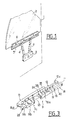
- a door 1 of a motor vehicle on which are mounted a window 2 and a window regulator mechanism 3 with two arms 4 oscillating on a support housing.
- the ends of the arms 4 are articulated in pads which can slide in a profile 5 fixed to a U-shaped profile 6 receiving the bottom of the window 2, of which the two profiles 5 and 6 are integral.
- the ends 11 of the arms 4 sliding in the skids can be spheres (ball joints) or any other suitable system.
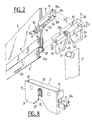
- the invention provides for coupling between the section 5 of the bottom of the window and the ends of the arms 4 by means of a shoe device 7 shown in FIGS. 2 to 8, each shoe 7 being articulated on one end 11 d 'an arm 4.
- Each shoe 7 is formed by two half-shoes 8 and 9 which can be displaced by sliding with respect to one another.
- the following half-shoe 8 will be called “upper half-shoe” and half-shoe 9 “lower half-shoe”, since they are actually in this relative position during mounting in the profile 5.
- the half-pads 8 and 9 are further provided with locking means one on the other in two respective stable positions: namely a first position called “mounting” before introduction of the end 11 of the arm 4 in the shoe 7 and in which the latter has a limited freedom of translation relative to the profile 5, and a second position after introduction of the end 11 into the shoe 7 and displacement by the end 11 of the upper half-shoe 8 relative to the lower half-shoe 9, called the "use" position.
- the terminal sphere 11 is locked in the shoe 7, which can slide freely in the profile 5.
- These locking means of the two half-pads 8, 9 comprise, arranged at the opposite ends thereof, elastic and flexible members 12, 13 which can be clamped with clamping on associated stop elements 14 and 15.
- the elastic members 12 and 13 belong to the lower half-pad 9 (of which they can be an integral part or be attached to it) while the elements 14 and 15 are part of the upper half-pad 8.
- the members 12 and 13 may both be on the same side of the half-roller 9 or be located on the opposite sides of the latter.
- the elastic member 12 is a flexible longitudinal tongue provided with an end portion 12a projecting laterally and forming an elbow substantially at right angles to the rest of the tongue 12.
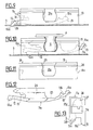
- the latter delimits with a longitudinal finger 40 the body 16 of the half-shoe 9 an elongated recess 17 which can receive the pin 14, while the tongue 12 moves laterally under the thrust of the latter.
- two notches or stops 18, 19 are provided for stopping the pin 14.
- the latter can indeed come to be placed between the stops 18 and 19, which then hold the half upper shoe 8 in its first stable locked position possible with respect to the half-shoe 9.
- the first stop 18 is rounded to allow the passage of the pin 14, while that the second stop 19 forms a blocking notch of the pin 14 against any subsequent progression.
- the second elastic member 13 is a flexible tab provided with a terminal hook 13a having a notch 13b. In its normal position where it is held elastically, the tab 13 has its hook 13a engaged on the corresponding lug 15 engaged in the notch 13b.
- the tongue 12, the lug 13, the pin 14 and the lug 15 are positioned and dimensioned so that the hook 13a is not engaged on the lug 15 when the pin 14 is locked between the stops 18 and 19 , and that the hook 13a comes on the lug 15 when, after sliding of the half-shoe 8 relative to the half-shoe 9, the pin 14 is completely released from the tongue 12 and that the latter returns laterally to its position rest (Fig. 7).
- a housing 21a, 21b is formed in the two half-pads 8, 9 to receive the end of the arm 4, as well as lateral notches 22, 23 for introducing the end 11 into the housing 21a, 21b, these notches being respectively formed in the half-pads 8 and 9.
- the end 11 being in the example described spherical, the housing 21a formed in the central part of the half-pad 8 has a corresponding truncated spherical shape, completed by the cylindrical portion 21b delimited by a cylindrical surface 24 formed on the lower half-roller 9. In the example shown, the cylindrical surface 24 is thus arranged between the notch 23 and the tongue 12.
- this portion 24 joins a step 35 itself extended by the flexible tab 13.
- the latter can undergo a certain angular movement relative to the underlying end 16b of the body 16, which delimits on this side the notch 23.
- the notches 22, 23 are flared or chamfered to facilitate the introduction of the sphere 11 into the housing 21a when the two half-pads 8, 9 are assembled.
- the notch 22 proper is extended externally by divergent edges or chamfers 25.
- the upper face of the half-shoe 8 has a longitudinal groove 26 in which a corresponding longitudinal flap 27 of the profile 5 can engage.
- the lower part 5a of the latter is U-shaped or V-shaped in order to receive the male conjugate end 28 of the half-shoe 9.
- a longitudinal slot 29 arranged to be able to cooperate with the end portion 12a of the tongue 12 during mounting of the pad 7 in its first stable locked position inside the section 5.
- the slot 29 is in fact arranged to receive the end portion 12a when the tongue 12 is laterally spaced apart by the pin 14 introduced into the recess 17, as will be explained below.
- the surface 24 of the half-shoe 9 is profiled so as to be complementary to the surface formed in the half-shoe 8 to receive the end of the arm 4, this end possibly being a sphere 11 or all other appropriate element.
- end hook 13a is positioned at one end of the half-shoe 9 so to be able to be released manually from the lug 15, which allows the unlocking and separation of the two half-pads 8, 9 if necessary.
- the height h1 of the half-shoe 9, excluding that of its profiled part 28, is equal to an interval h2 formed on the half-shoe.
- pad 8 between a longitudinal shoulder 20 and a bar 30. The latter is orthogonal to the two cheeks 31 delimiting the notch 22 and on the inner face of which the shoulder 20 is formed.
- the half-shoes 8 and 9 are fitted into each other by introducing the half-shoe 9 into the height clearance h2 of the half-shoe 8. To do this, the lower half-shoe is oriented. 9 so that the pin 14 comes into the recess 17 and slides along the tongue 12 until it is locked in position between the stops 18 and 19. The two half-pads 8, 9 are then in their first stable locked position called “mounting" (Fig.4).
- the arms 4 of the window regulator are in the assembly position, and the window 2 provided with its sections 5 and 6 and the pads 7 is lowered onto the spheres 11.
- the robot maneuvers the arm 4 so as to bring first of all the end portion 12a abuts against one of the ends of the lumen 29 (FIG. 6). From this moment the lower half-pad 9 is immobilized while the sphere 11 continues to drive the half-pad 8 in translation. Therefore, in each pad 7 the pins 14 are released from the stops 18 and 19, then slide along the tongues 12, and as soon as they have passed the end parts 12a of these, the released tongues 12 fold elastically inside the profile 5 at the same time as the hooks 13a come to engage on the pins 15 (Fig. 7).
- the stop 18 of the tongue 12 could be eliminated, the half-shoe 9 then being blocked only in one direction with respect to the half-shoe 8. It would still be possible then to carry out the passage of the first stable locked position at the second locked position, but this variant would naturally be less advantageous than that with two stops 18, 19.
- cylindrical part 21b can be extended on the tab 12 in the direction of the terminal part 12a, possibly up to the latter, and / or on the finger 40.
- the light 29 also allows a longitudinal displacement of the half-shoe 8 when the sphere 11 comes into contact with one of the edges 25.
- the shoe 7a consists of two half-shoes 8a, 9a.
- the half-shoe 9a is entirely housed in the half-shoe 8a, inside which it can slide like a drawer.
- the half-shoe 8a receiving this drawer 9a is then provided with all of the guide means (26, 28, 30) on the conjugated parts (5a, 27) of the profile rail 5.
- the elastic locking members 12, 13 are produced on the half-shoe or drawer 9a.
- the stopper 18 is eliminated and that the stopper 19 is formed in the wall of the recess 17 opposite the tongue 12.
- the other parts of the pad 7a similar to those of the pad 7, have been identified by the same references.
- the mounting of the half-pad 9a in the half-pad 8a closes the housing 21a by its surface 24, the mounting of the pad 7a in the profile 5 being also identical.
- This variant ensures better guidance of the shoe 7a in the profile 5, because all the guide surfaces belong to the same half-shoe 8a, which is not the case for the shoe 7.
Landscapes
- Window Of Vehicle (AREA)
- Automobile Manufacture Line, Endless Track Vehicle, Trailer (AREA)
- Footwear And Its Accessory, Manufacturing Method And Apparatuses (AREA)
- Securing Of Glass Panes Or The Like (AREA)
Applications Claiming Priority (2)
| Application Number | Priority Date | Filing Date | Title |
|---|---|---|---|
| FR8815026A FR2639395B1 (fr) | 1988-11-18 | 1988-11-18 | Dispositif d'accouplement entre une vitre et un mecanisme de leve-vitre a bras oscillants dans un vehicule automobile |
| FR8815026 | 1988-11-18 |
Publications (2)
| Publication Number | Publication Date |
|---|---|
| EP0369853A1 true EP0369853A1 (de) | 1990-05-23 |
| EP0369853B1 EP0369853B1 (de) | 1993-08-04 |
Family
ID=9371979
Family Applications (1)
| Application Number | Title | Priority Date | Filing Date |
|---|---|---|---|
| EP19890403009 Expired - Lifetime EP0369853B1 (de) | 1988-11-18 | 1989-10-31 | Kupplungsvorrichtung zwischen Fenster und Fensterheber mit schwingenden Armen in einem Kraftfahrzeug |
Country Status (7)
| Country | Link |
|---|---|
| EP (1) | EP0369853B1 (de) |
| JP (1) | JPH086526B2 (de) |
| BR (1) | BR8905841A (de) |
| CA (1) | CA2002659A1 (de) |
| DE (1) | DE68908097T2 (de) |
| ES (1) | ES2044183T3 (de) |
| FR (1) | FR2639395B1 (de) |
Cited By (4)
| Publication number | Priority date | Publication date | Assignee | Title |
|---|---|---|---|---|
| GB2319050A (en) * | 1996-10-15 | 1998-05-13 | Nissan Europ Tech Centre | Means of locating a car window glass holder to the carrier plate of the window regulator |
| WO2004057142A3 (de) * | 2002-12-20 | 2004-10-28 | Brose Fahrzeugteile | Fensterheber |
| US8207227B2 (en) | 1999-04-05 | 2012-06-26 | Emisphere Technologies, Inc. | Disodium salts, monohydrates, and ethanol solvates for delivering active agents |
| US8650800B2 (en) * | 2012-03-09 | 2014-02-18 | Toyota Motor Engineering & Manufacturing North America, Inc. | Window lift assemblies for vehicles including window support bracket assemblies |
Families Citing this family (1)
| Publication number | Priority date | Publication date | Assignee | Title |
|---|---|---|---|---|
| CN116533723B (zh) * | 2023-06-29 | 2025-08-26 | 长沙永昌车辆零部件有限公司 | 一种无阶差的车窗玻璃挂接结构 |
Citations (4)
| Publication number | Priority date | Publication date | Assignee | Title |
|---|---|---|---|---|
| GB1024058A (en) * | 1965-02-05 | 1966-03-30 | Ford Motor Co | Sliding window assemblies |
| US3466802A (en) * | 1968-06-17 | 1969-09-16 | Gen Motors Corp | Slidable guide assembly |
| DE8523650U1 (de) * | 1985-08-16 | 1985-10-03 | Brose Fahrzeugteile GmbH & Co KG, 8630 Coburg | Fensterheber, insbesondere für Kraftfahrzeuge |
| WO1987004126A1 (en) * | 1986-01-10 | 1987-07-16 | Ab Volvo | Device for attaching an up- and downwardly movable window to a regulator mechanism |
-
1988
- 1988-11-18 FR FR8815026A patent/FR2639395B1/fr not_active Expired - Fee Related
-
1989
- 1989-10-31 EP EP19890403009 patent/EP0369853B1/de not_active Expired - Lifetime
- 1989-10-31 DE DE1989608097 patent/DE68908097T2/de not_active Expired - Fee Related
- 1989-10-31 ES ES89403009T patent/ES2044183T3/es not_active Expired - Lifetime
- 1989-11-09 CA CA 2002659 patent/CA2002659A1/en not_active Abandoned
- 1989-11-17 JP JP29775089A patent/JPH086526B2/ja not_active Expired - Lifetime
- 1989-11-20 BR BR898905841A patent/BR8905841A/pt unknown
Patent Citations (4)
| Publication number | Priority date | Publication date | Assignee | Title |
|---|---|---|---|---|
| GB1024058A (en) * | 1965-02-05 | 1966-03-30 | Ford Motor Co | Sliding window assemblies |
| US3466802A (en) * | 1968-06-17 | 1969-09-16 | Gen Motors Corp | Slidable guide assembly |
| DE8523650U1 (de) * | 1985-08-16 | 1985-10-03 | Brose Fahrzeugteile GmbH & Co KG, 8630 Coburg | Fensterheber, insbesondere für Kraftfahrzeuge |
| WO1987004126A1 (en) * | 1986-01-10 | 1987-07-16 | Ab Volvo | Device for attaching an up- and downwardly movable window to a regulator mechanism |
Cited By (6)
| Publication number | Priority date | Publication date | Assignee | Title |
|---|---|---|---|---|
| GB2319050A (en) * | 1996-10-15 | 1998-05-13 | Nissan Europ Tech Centre | Means of locating a car window glass holder to the carrier plate of the window regulator |
| GB2319050B (en) * | 1996-10-15 | 2000-11-15 | Nissan Europ Technology Ct Ltd | Glass holding means and carrier plate for a vehicle window regulator |
| US8207227B2 (en) | 1999-04-05 | 2012-06-26 | Emisphere Technologies, Inc. | Disodium salts, monohydrates, and ethanol solvates for delivering active agents |
| US8658695B2 (en) | 1999-04-05 | 2014-02-25 | Emisphere Technologies, Inc. | Disodium salts, monohydrates, and ethanol solvates for delivering active agents |
| WO2004057142A3 (de) * | 2002-12-20 | 2004-10-28 | Brose Fahrzeugteile | Fensterheber |
| US8650800B2 (en) * | 2012-03-09 | 2014-02-18 | Toyota Motor Engineering & Manufacturing North America, Inc. | Window lift assemblies for vehicles including window support bracket assemblies |
Also Published As
| Publication number | Publication date |
|---|---|
| JPH086526B2 (ja) | 1996-01-24 |
| FR2639395B1 (fr) | 1991-02-15 |
| BR8905841A (pt) | 1990-06-12 |
| EP0369853B1 (de) | 1993-08-04 |
| CA2002659A1 (en) | 1990-05-18 |
| DE68908097T2 (de) | 1993-11-18 |
| ES2044183T3 (es) | 1994-01-01 |
| FR2639395A1 (fr) | 1990-05-25 |
| JPH02183067A (ja) | 1990-07-17 |
| DE68908097D1 (de) | 1993-09-09 |
Similar Documents
| Publication | Publication Date | Title |
|---|---|---|
| EP1026349B1 (de) | Griff für einen Kraftfahrzeugflügel | |
| EP0572313A1 (de) | Kugelbefestigung für Fahrzeugscheinwerferreflektor | |
| EP3203000B1 (de) | Schloss eines öffnungsflügels mit einem elastisch einklinkbaren sockel | |
| EP0369853B1 (de) | Kupplungsvorrichtung zwischen Fenster und Fensterheber mit schwingenden Armen in einem Kraftfahrzeug | |
| FR2582916A1 (fr) | Boucle, notamment de ceinture de securite. | |
| FR2767096A1 (fr) | Glissiere pour siege de vehicules automobiles, comportant un verrou constitue d'une lame elastiquement flexible | |
| FR2733635A1 (fr) | Connecteur electrique a poignee d'actionnement perfectionne | |
| FR3084618A1 (fr) | Dispositif de guidage d'un ouvrant de vehicule | |
| FR3094960A1 (fr) | Système d’installation pour une cabine d’un véhicule | |
| EP3967531B1 (de) | Vorrichtung zur abdichtung eines in die karosserie eines fahrzeugs eingelassenen öffnungsfelds, und entsprechendes fahrzeug | |
| FR2865166A1 (fr) | Siege de vehicule coulissant et glissiere pour un tel siege. | |
| FR2876959A1 (fr) | Dispositif d'ouvrant pour vehicule automobile | |
| EP0597764B1 (de) | Fensterheber für ein Kraftfahrzeug | |
| WO1990015192A1 (fr) | Dispositif de fixation de rail de voie ferree sur un support | |
| FR2721649A1 (fr) | Arrêt de porte à deux positions pour véhicule automobile. | |
| FR2888539A1 (fr) | Siege de vehicule coulissant et glissiere pour un tel siege | |
| FR2810283A3 (fr) | Dispositif de fixation d'un feu dans une ouverture de carrosserie de vehicule | |
| EP1747935A2 (de) | Gleitanordnung und Möbelstück mit Gleitanordnung für Fahrzeuginnenraum | |
| FR2895939A1 (fr) | Crochet de reception d'un tourillon d'articulation | |
| EP0543706A1 (de) | Vorrichtung zum automatischen Kuppeln einer Sicherheitsgurtverankerung mit dem Boden eines Fahrzeuges | |
| EP0876946A1 (de) | Türschliesser, damit ausgerüstete Tür und Schienenfahrzeug mit mindestens einer derartigen Vorrichtung und/oder Tür | |
| FR2555235A1 (fr) | Dispositif de blocage d'un organe, en particulier le volet ou la ridelle d'un vehicule a plate-forme | |
| EP2320012B1 (de) | Verschluss für die Klappe eines Kastens | |
| FR2851605A1 (fr) | Dispositif de fixation sur un bati d'un ensemble moteur d'actionnement d'une porte, et installation d'actionnement correspondante | |
| EP0430759B1 (de) | Fahrzeugfeststellbremssteuervorrichtung |
Legal Events
| Date | Code | Title | Description |
|---|---|---|---|
| PUAI | Public reference made under article 153(3) epc to a published international application that has entered the european phase |
Free format text: ORIGINAL CODE: 0009012 |
|
| AK | Designated contracting states |
Kind code of ref document: A1 Designated state(s): DE ES GB IT SE |
|
| 17P | Request for examination filed |
Effective date: 19901010 |
|
| RAP1 | Party data changed (applicant data changed or rights of an application transferred) |
Owner name: ROCKWELL AUTOMOTIVE BODY SYSTEMS-FRANCE EN ABREGE: |
|
| 17Q | First examination report despatched |
Effective date: 19920416 |
|
| GRAA | (expected) grant |
Free format text: ORIGINAL CODE: 0009210 |
|
| AK | Designated contracting states |
Kind code of ref document: B1 Designated state(s): DE ES GB IT SE |
|
| REF | Corresponds to: |
Ref document number: 68908097 Country of ref document: DE Date of ref document: 19930909 |
|
| ITF | It: translation for a ep patent filed | ||
| PGFP | Annual fee paid to national office [announced via postgrant information from national office to epo] |
Ref country code: SE Payment date: 19931026 Year of fee payment: 5 Ref country code: GB Payment date: 19931026 Year of fee payment: 5 |
|
| PGFP | Annual fee paid to national office [announced via postgrant information from national office to epo] |
Ref country code: ES Payment date: 19931027 Year of fee payment: 5 |
|
| GBT | Gb: translation of ep patent filed (gb section 77(6)(a)/1977) |
Effective date: 19931112 |
|
| REG | Reference to a national code |
Ref country code: ES Ref legal event code: FG2A Ref document number: 2044183 Country of ref document: ES Kind code of ref document: T3 |
|
| PLBE | No opposition filed within time limit |
Free format text: ORIGINAL CODE: 0009261 |
|
| STAA | Information on the status of an ep patent application or granted ep patent |
Free format text: STATUS: NO OPPOSITION FILED WITHIN TIME LIMIT |
|
| 26N | No opposition filed | ||
| PG25 | Lapsed in a contracting state [announced via postgrant information from national office to epo] |
Ref country code: GB Effective date: 19941031 |
|
| PG25 | Lapsed in a contracting state [announced via postgrant information from national office to epo] |
Ref country code: SE Effective date: 19941101 |
|
| PG25 | Lapsed in a contracting state [announced via postgrant information from national office to epo] |
Ref country code: ES Free format text: LAPSE BECAUSE OF THE APPLICANT RENOUNCES Effective date: 19941102 |
|
| EAL | Se: european patent in force in sweden |
Ref document number: 89403009.7 |
|
| GBPC | Gb: european patent ceased through non-payment of renewal fee |
Effective date: 19941031 |
|
| EUG | Se: european patent has lapsed |
Ref document number: 89403009.7 |
|
| PGFP | Annual fee paid to national office [announced via postgrant information from national office to epo] |
Ref country code: DE Payment date: 19960923 Year of fee payment: 8 |
|
| PG25 | Lapsed in a contracting state [announced via postgrant information from national office to epo] |
Ref country code: DE Free format text: LAPSE BECAUSE OF NON-PAYMENT OF DUE FEES Effective date: 19980701 |
|
| REG | Reference to a national code |
Ref country code: ES Ref legal event code: FD2A Effective date: 19991007 |
|
| PG25 | Lapsed in a contracting state [announced via postgrant information from national office to epo] |
Ref country code: IT Free format text: LAPSE BECAUSE OF NON-PAYMENT OF DUE FEES;WARNING: LAPSES OF ITALIAN PATENTS WITH EFFECTIVE DATE BEFORE 2007 MAY HAVE OCCURRED AT ANY TIME BEFORE 2007. THE CORRECT EFFECTIVE DATE MAY BE DIFFERENT FROM THE ONE RECORDED. Effective date: 20051031 |