EP0369855B1 - Automatische Einheit zum Verteilen und Setzen von Ringen, insbesondere Kompositringen auf Motorkolben - Google Patents
Automatische Einheit zum Verteilen und Setzen von Ringen, insbesondere Kompositringen auf Motorkolben Download PDFInfo
- Publication number
- EP0369855B1 EP0369855B1 EP89403054A EP89403054A EP0369855B1 EP 0369855 B1 EP0369855 B1 EP 0369855B1 EP 89403054 A EP89403054 A EP 89403054A EP 89403054 A EP89403054 A EP 89403054A EP 0369855 B1 EP0369855 B1 EP 0369855B1
- Authority
- EP
- European Patent Office
- Prior art keywords
- rings
- pistons
- unit according
- piston
- ring
- Prior art date
- Legal status (The legal status is an assumption and is not a legal conclusion. Google has not performed a legal analysis and makes no representation as to the accuracy of the status listed.)
- Expired - Lifetime
Links
Images


Classifications
-
- B—PERFORMING OPERATIONS; TRANSPORTING
- B23—MACHINE TOOLS; METAL-WORKING NOT OTHERWISE PROVIDED FOR
- B23P—METAL-WORKING NOT OTHERWISE PROVIDED FOR; COMBINED OPERATIONS; UNIVERSAL MACHINE TOOLS
- B23P19/00—Machines for simply fitting together or separating metal parts or objects, or metal and non-metal parts, whether or not involving some deformation; Tools or devices therefor so far as not provided for in other classes
- B23P19/04—Machines for simply fitting together or separating metal parts or objects, or metal and non-metal parts, whether or not involving some deformation; Tools or devices therefor so far as not provided for in other classes for assembling or disassembling parts
- B23P19/08—Machines for placing washers, circlips, or the like on bolts or other members
- B23P19/084—Machines for placing washers, circlips, or the like on bolts or other members for placing resilient or flexible rings, e.g. O-rings, circlips
- B23P19/088—Piston rings in piston grooves
-
- B—PERFORMING OPERATIONS; TRANSPORTING
- B23—MACHINE TOOLS; METAL-WORKING NOT OTHERWISE PROVIDED FOR
- B23P—METAL-WORKING NOT OTHERWISE PROVIDED FOR; COMBINED OPERATIONS; UNIVERSAL MACHINE TOOLS
- B23P19/00—Machines for simply fitting together or separating metal parts or objects, or metal and non-metal parts, whether or not involving some deformation; Tools or devices therefor so far as not provided for in other classes
- B23P19/001—Article feeders for assembling machines
- B23P19/003—Escapement mechanisms used therewith
-
- Y—GENERAL TAGGING OF NEW TECHNOLOGICAL DEVELOPMENTS; GENERAL TAGGING OF CROSS-SECTIONAL TECHNOLOGIES SPANNING OVER SEVERAL SECTIONS OF THE IPC; TECHNICAL SUBJECTS COVERED BY FORMER USPC CROSS-REFERENCE ART COLLECTIONS [XRACs] AND DIGESTS
- Y10—TECHNICAL SUBJECTS COVERED BY FORMER USPC
- Y10T—TECHNICAL SUBJECTS COVERED BY FORMER US CLASSIFICATION
- Y10T24/00—Buckles, buttons, clasps, etc.
- Y10T24/37—Drawstring, laced-fastener, or separate essential cooperating device therefor
- Y10T24/375—Drawstring, laced-fastener, or separate essential cooperating device therefor having hook shaped directing means
- Y10T24/3753—Drawstring, laced-fastener, or separate essential cooperating device therefor having hook shaped directing means and movable component or surface for closing throat
-
- Y—GENERAL TAGGING OF NEW TECHNOLOGICAL DEVELOPMENTS; GENERAL TAGGING OF CROSS-SECTIONAL TECHNOLOGIES SPANNING OVER SEVERAL SECTIONS OF THE IPC; TECHNICAL SUBJECTS COVERED BY FORMER USPC CROSS-REFERENCE ART COLLECTIONS [XRACs] AND DIGESTS
- Y10—TECHNICAL SUBJECTS COVERED BY FORMER USPC
- Y10T—TECHNICAL SUBJECTS COVERED BY FORMER US CLASSIFICATION
- Y10T29/00—Metal working
- Y10T29/53—Means to assemble or disassemble
- Y10T29/536—Piston ring inserter or remover
Definitions
- the present invention relates to an automatic unit for distributing and fitting segments, particularly composite ones, on pistons of internal combustion engines presented by a robot on this unit of the type integrated in a robotic assembly line, and provided with automatic means for gripping the pistons, detecting the type of pistons removed, initializing and referencing the piston grooves in height on the segment stacking warheads, selection and presentation of the warheads.
- the invention therefore aims to remedy these drawbacks, in the simplest way.
- the object of the present invention is therefore an automatic unit as defined in claim 1.
- This arrangement allows an effective separation of these expanders for the installation of composite segments on the pistons.
- this unit comprises a device for automatically placing open segments expanded when passing over a corresponding warhead, which essentially consists of a plurality of fingers of elastomeric material and with an inverted corolla configuration.
- This device makes it very easy to take the segments through the feed drawer and ensure their expansion over the length of the receiving warhead.
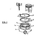
- FIG. 1 shows a scraper composite segment 1 which comprises an intermediate elastic part 1a, called an expander, held between two thin flat rings 1b and 1c, as well as a sealing segment 2 and a gun segment 3.
- an intermediate elastic part 1a called an expander
- the segments arrive previously stacked in magazines 4 oriented along the slots.
- FIGS. 2 to 8 They are separated by means of a specific separation device 6 illustrated in FIGS. 2 to 8 in the case of expanders 1a commonly designated “U-flex segments", or by means of a drawer 8 in the case of the rings thin 1b and 1c.
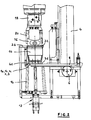
- An annex device 12 provided with a jack carries a set of six fingers 14 made of elastomeric material such as polyurethane.
- the arrangement of these fingers in inverted corolla makes it possible, on the one hand, to take the segment through the drawer 8 and, on the other hand, to ensure, thanks to the elasticity of this material, the expansion over all the length of the warhead 10 ( Figure 2).
- a piston 16 to be fitted with segments is gripped by a clamp 18 with four fingers 20 moving in pairs two by two. Then, it is deposited on a reference surface where it is re-entered by this clamp at a known level ( Figure 2).
- This operation aims to place the grooves 22 to receive the segments at a known dimension.
- the piston 16 is then transferred above the warhead 10 in which it descends to the level of fitting of the corresponding segment.
- the device 12 for automatic positioning of segments ensures that the segment will come into abutment against a reconformation ceiling 24, and guarantees the release of this segment at the end of the warhead.
- the piston 16 is then released from the warhead, with the segment mounted ( Figure 2).
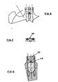
- the expander separation device 1a comprises two pairs of helical ramps with opposite winding directions (two on the right 26, 27 and two on the left 28, 29) which are driven simultaneously by a ring gear 30.
- Two propellers are opposite in direction to the other two to balance the friction forces produced between said ramps and the expander whose rotation is not desired.
- the exit from the helical ramps corresponds to the end of the magazine 4 (held by the interior of the expander).
- the expander 1a then comes to be housed in a cavity 36 formed in the automatic feeding drawer 8 (FIG. 2).
- a finger 38 maintains the latter during transport under the warhead 10 where it is retracted by a knife 40. It is returned to its initial position by two springs 42 ( Figures 6, 7 and 8).
Landscapes
- Engineering & Computer Science (AREA)
- Mechanical Engineering (AREA)
- Automatic Assembly (AREA)
- Valve Device For Special Equipments (AREA)
- Pistons, Piston Rings, And Cylinders (AREA)
- Pharmaceuticals Containing Other Organic And Inorganic Compounds (AREA)
- Medicinal Preparation (AREA)
- Medicines That Contain Protein Lipid Enzymes And Other Medicines (AREA)
- Fuel-Injection Apparatus (AREA)
Claims (6)
Priority Applications (1)
| Application Number | Priority Date | Filing Date | Title |
|---|---|---|---|
| AT89403054T ATE79581T1 (de) | 1988-11-18 | 1989-11-07 | Automatische einheit zum verteilen und setzen von ringen, insbesondere kompositringen auf motorkolben. |
Applications Claiming Priority (2)
| Application Number | Priority Date | Filing Date | Title |
|---|---|---|---|
| FR8815031 | 1988-11-18 | ||
| FR8815031A FR2639271B1 (fr) | 1988-11-18 | 1988-11-18 | Unite de distribution et de pose de segments notamment composites sur des pistons de moteurs |
Publications (2)
| Publication Number | Publication Date |
|---|---|
| EP0369855A1 EP0369855A1 (de) | 1990-05-23 |
| EP0369855B1 true EP0369855B1 (de) | 1992-08-19 |
Family
ID=9371980
Family Applications (1)
| Application Number | Title | Priority Date | Filing Date |
|---|---|---|---|
| EP89403054A Expired - Lifetime EP0369855B1 (de) | 1988-11-18 | 1989-11-07 | Automatische Einheit zum Verteilen und Setzen von Ringen, insbesondere Kompositringen auf Motorkolben |
Country Status (7)
| Country | Link |
|---|---|
| US (1) | US4967459A (de) |
| EP (1) | EP0369855B1 (de) |
| AT (1) | ATE79581T1 (de) |
| CA (1) | CA2003310A1 (de) |
| DE (1) | DE68902537T2 (de) |
| ES (1) | ES2034712T3 (de) |
| FR (1) | FR2639271B1 (de) |
Families Citing this family (9)
| Publication number | Priority date | Publication date | Assignee | Title |
|---|---|---|---|---|
| FR2679812B1 (fr) * | 1991-07-31 | 1995-11-10 | Floquet Monopole | Machine pour la pose automatique de segments sur des pistons. |
| US5303465A (en) * | 1992-04-27 | 1994-04-19 | Honda Giken Kogyo Kabushiki Kaisha | Method of assembling piston ring and method of assembling set oil ring and apparatus for assembling set oil ring |
| US5435056A (en) * | 1993-10-15 | 1995-07-25 | Micro-Precision Operations, Inc. | Piston ring apparatus |
| US5404629A (en) * | 1993-10-15 | 1995-04-11 | Micro-Precision Operations, Inc. | Piston ring apparatus |
| JPH07178629A (ja) * | 1993-12-22 | 1995-07-18 | Honda Motor Co Ltd | ピストンに対する組オイルリングの組付方法 |
| US5601540A (en) * | 1995-07-14 | 1997-02-11 | Stevens; Brian | Apparatus for positioning a split ring over an enlarged flange |
| FR2763876B1 (fr) * | 1997-05-27 | 1999-08-27 | Renault Automation | Dispositif de depilement d'elements ecarteurs entrant dans la constitution d'un segment racleur d'huile |
| JP4249183B2 (ja) * | 2003-12-12 | 2009-04-02 | 平田機工株式会社 | ピストンリング装着装置及び方法 |
| TWI597443B (zh) * | 2015-07-27 | 2017-09-01 | 泰茂實業股份有限公司 | 活塞環安裝輔助裝置 |
Citations (1)
| Publication number | Priority date | Publication date | Assignee | Title |
|---|---|---|---|---|
| EP0341161A1 (de) * | 1988-05-05 | 1989-11-08 | Renault Automation | Automatische Maschine zum Verteilen und Setzen von Ringen auf Verbrennungsmotorkolben |
Family Cites Families (15)
| Publication number | Priority date | Publication date | Assignee | Title |
|---|---|---|---|---|
| US1525528A (en) * | 1920-09-10 | 1925-02-10 | American Can Co | Curling, counting, and stacking device |
| US1634566A (en) * | 1923-04-03 | 1927-07-05 | Individual Drinking Cup Co | Cup dispenser |
| US2792625A (en) * | 1956-03-21 | 1957-05-21 | Gen Motors Corp | Ring assembly machine |
| US3018593A (en) * | 1960-02-12 | 1962-01-30 | Aluminum Co Of America | Release and transfer device |
| US3793695A (en) * | 1972-08-29 | 1974-02-26 | Sealed Power Corp | Device for automatically loading an oil ring spacer-expander into the oil ring groove of a piston |
| US3889342A (en) * | 1973-09-12 | 1975-06-17 | Ramsey Corp | Apparatus for assembling piston ring end guides |
| US3977566A (en) * | 1975-10-31 | 1976-08-31 | Bell Telephone Laboratories, Incorporated | Semiconductor wafer handling apparatus |
| US4047276A (en) * | 1975-11-28 | 1977-09-13 | Designeers Midwest | Apparatus for dispensing rings and for applying piston rings to pistons |
| DE2840863C2 (de) * | 1978-09-20 | 1982-08-26 | Goetze Ag, 5093 Burscheid | Vorrichtung zum Positionieren von unrunden Kolbenringen |
| JPS6139695Y2 (de) * | 1980-05-19 | 1986-11-13 | ||
| JPS5741147A (en) * | 1980-08-12 | 1982-03-08 | Nippon Piston Ring Co Ltd | Constant number piston ring separating device |
| US4379234A (en) * | 1981-05-15 | 1983-04-05 | Cummins Engine Company, Inc. | Electro optic controlled piston ring installing apparatus |
| JPS58181525A (ja) * | 1982-04-14 | 1983-10-24 | Nippon Piston Ring Co Ltd | ピストンリング自動插入装置 |
| JPS58206331A (ja) * | 1982-05-28 | 1983-12-01 | Nippon Piston Ring Co Ltd | ピストンリング自動插入装置 |
| JPH0780096B2 (ja) * | 1987-01-16 | 1995-08-30 | 本田技研工業株式会社 | ピストンのピストンリング自動組込装置 |
-
1988
- 1988-11-18 FR FR8815031A patent/FR2639271B1/fr not_active Expired - Lifetime
-
1989
- 1989-11-07 EP EP89403054A patent/EP0369855B1/de not_active Expired - Lifetime
- 1989-11-07 AT AT89403054T patent/ATE79581T1/de active
- 1989-11-07 DE DE8989403054T patent/DE68902537T2/de not_active Expired - Fee Related
- 1989-11-07 ES ES198989403054T patent/ES2034712T3/es not_active Expired - Lifetime
- 1989-11-17 CA CA002003310A patent/CA2003310A1/en not_active Abandoned
- 1989-11-17 US US07/437,616 patent/US4967459A/en not_active Expired - Fee Related
Patent Citations (1)
| Publication number | Priority date | Publication date | Assignee | Title |
|---|---|---|---|---|
| EP0341161A1 (de) * | 1988-05-05 | 1989-11-08 | Renault Automation | Automatische Maschine zum Verteilen und Setzen von Ringen auf Verbrennungsmotorkolben |
Also Published As
| Publication number | Publication date |
|---|---|
| US4967459A (en) | 1990-11-06 |
| DE68902537D1 (de) | 1992-09-24 |
| FR2639271B1 (fr) | 1990-12-28 |
| DE68902537T2 (de) | 1993-03-25 |
| ES2034712T3 (es) | 1993-04-01 |
| EP0369855A1 (de) | 1990-05-23 |
| FR2639271A1 (fr) | 1990-05-25 |
| CA2003310A1 (en) | 1990-05-18 |
| ATE79581T1 (de) | 1992-09-15 |
Similar Documents
| Publication | Publication Date | Title |
|---|---|---|
| EP0369855B1 (de) | Automatische Einheit zum Verteilen und Setzen von Ringen, insbesondere Kompositringen auf Motorkolben | |
| EP1092939B1 (de) | Vorrichtung zum Befestigen eines Hülsenbodens an einer Treibladungshülse und Hülsenboden für eine solche Befestigungseinrichtung | |
| FR2664883A1 (fr) | Margeur rotatif pour le placement precis d'elements en feuille sur des supports plats. | |
| EP0723086B1 (de) | Schraube mit einem trennbaren Schraubenkopf und Schraubwerkzeug für eine solche Schraube | |
| WO1989003015A2 (fr) | Projectile destine a etre tire par une arme a feu | |
| FR2946423A1 (fr) | Dispositif d'ouverture et de verrouillage d'un empennage de munition | |
| CH607979A5 (en) | Device for handling stackable articles | |
| EP1475601B1 (de) | Unterkalibergeschoss, Penetrator und Treibspiegel für ein solches Geschoss | |
| EP3430347B1 (de) | Zielabschussvorrichtung | |
| EP0539257B1 (de) | Trägergeschoss | |
| EP0401115B1 (de) | Vorrichtung zum Halten eines Geschosses in bezug auf das Gehäuse einer teleskopartigen Munition | |
| EP3194310B1 (de) | Vorrichtung zur trennung von kleinen losen objekten | |
| EP2253926B1 (de) | Vorrichtung zum Trennen von Treibladungsmodulen | |
| FR2668204A1 (fr) | Mecanisme de demarreur de moteur. | |
| EP0457627B1 (de) | Vorrichtung zum Zuführen von Ringen zu einer automatischen Maschine zum Setzen von Ringen auf Verbrennungsmotorkolben | |
| EP4194119A1 (de) | Multitasking-vorrichtung mit einer vorrichtung zum abführen zu einem abfallbereich eines als nicht konform identifizierten niets oder temporären befestigung | |
| EP0580914A1 (de) | Tontaubenabschussvorrichtung für das Sportschiessen | |
| US10267609B1 (en) | Cartridge reloading machine and components | |
| EP1596150B1 (de) | Vorrichtung zum Trennen von Treibladungsmodulen | |
| FR2627411A1 (fr) | Dispositif et procede pour la mise en place automatique de colliers de serrage | |
| EP0000451B1 (de) | Klemme zum Festhalten von Gegenständen, Vorrichtung zum Anhängen zum Abhängen und zum Überlappen einer derartigen Klemme, und Anwendung dieser Klemme dieser Vorrichtung in Behandlungsanlagen | |
| WO2020193478A1 (fr) | Machine portable pour relier des maillons et des munitions | |
| EP0531594B1 (de) | Vorrichtung zum Zuführen von Munition zu einer Maschinenwaffe | |
| CA1142027A (fr) | Munition pour arme a feu et son procede de fabrication | |
| EP0628478B1 (de) | Vorrichtung zum Auswerfen eines mit einer Struktur lösbar verbundenen Objektes |
Legal Events
| Date | Code | Title | Description |
|---|---|---|---|
| PUAI | Public reference made under article 153(3) epc to a published international application that has entered the european phase |
Free format text: ORIGINAL CODE: 0009012 |
|
| 17P | Request for examination filed |
Effective date: 19891110 |
|
| AK | Designated contracting states |
Kind code of ref document: A1 Designated state(s): AT BE CH DE ES GB GR IT LI NL SE |
|
| 17Q | First examination report despatched |
Effective date: 19910426 |
|
| GRAA | (expected) grant |
Free format text: ORIGINAL CODE: 0009210 |
|
| AK | Designated contracting states |
Kind code of ref document: B1 Designated state(s): AT BE CH DE ES GB GR IT LI NL SE |
|
| PG25 | Lapsed in a contracting state [announced via postgrant information from national office to epo] |
Ref country code: NL Effective date: 19920819 Ref country code: GR Free format text: LAPSE BECAUSE OF FAILURE TO SUBMIT A TRANSLATION OF THE DESCRIPTION OR TO PAY THE FEE WITHIN THE PRESCRIBED TIME-LIMIT Effective date: 19920819 Ref country code: AT Effective date: 19920819 |
|
| REF | Corresponds to: |
Ref document number: 79581 Country of ref document: AT Date of ref document: 19920915 Kind code of ref document: T |
|
| ITF | It: translation for a ep patent filed | ||
| GBT | Gb: translation of ep patent filed (gb section 77(6)(a)/1977) | ||
| REF | Corresponds to: |
Ref document number: 68902537 Country of ref document: DE Date of ref document: 19920924 |
|
| PG25 | Lapsed in a contracting state [announced via postgrant information from national office to epo] |
Ref country code: LI Effective date: 19921130 Ref country code: CH Effective date: 19921130 |
|
| NLV1 | Nl: lapsed or annulled due to failure to fulfill the requirements of art. 29p and 29m of the patents act | ||
| REG | Reference to a national code |
Ref country code: ES Ref legal event code: FG2A Ref document number: 2034712 Country of ref document: ES Kind code of ref document: T3 |
|
| PLBE | No opposition filed within time limit |
Free format text: ORIGINAL CODE: 0009261 |
|
| STAA | Information on the status of an ep patent application or granted ep patent |
Free format text: STATUS: NO OPPOSITION FILED WITHIN TIME LIMIT |
|
| REG | Reference to a national code |
Ref country code: CH Ref legal event code: PL |
|
| 26N | No opposition filed | ||
| EAL | Se: european patent in force in sweden |
Ref document number: 89403054.3 |
|
| PGFP | Annual fee paid to national office [announced via postgrant information from national office to epo] |
Ref country code: GB Payment date: 19971013 Year of fee payment: 9 |
|
| PGFP | Annual fee paid to national office [announced via postgrant information from national office to epo] |
Ref country code: SE Payment date: 19971024 Year of fee payment: 9 |
|
| PGFP | Annual fee paid to national office [announced via postgrant information from national office to epo] |
Ref country code: BE Payment date: 19971030 Year of fee payment: 9 |
|
| PGFP | Annual fee paid to national office [announced via postgrant information from national office to epo] |
Ref country code: DE Payment date: 19971115 Year of fee payment: 9 |
|
| PGFP | Annual fee paid to national office [announced via postgrant information from national office to epo] |
Ref country code: ES Payment date: 19971117 Year of fee payment: 9 |
|
| PG25 | Lapsed in a contracting state [announced via postgrant information from national office to epo] |
Ref country code: GB Free format text: LAPSE BECAUSE OF NON-PAYMENT OF DUE FEES Effective date: 19981107 |
|
| PG25 | Lapsed in a contracting state [announced via postgrant information from national office to epo] |
Ref country code: SE Free format text: LAPSE BECAUSE OF NON-PAYMENT OF DUE FEES Effective date: 19981108 |
|
| PG25 | Lapsed in a contracting state [announced via postgrant information from national office to epo] |
Ref country code: ES Free format text: LAPSE BECAUSE OF EXPIRATION OF PROTECTION Effective date: 19981110 |
|
| PG25 | Lapsed in a contracting state [announced via postgrant information from national office to epo] |
Ref country code: BE Free format text: LAPSE BECAUSE OF NON-PAYMENT OF DUE FEES Effective date: 19981130 |
|
| BERE | Be: lapsed |
Owner name: RENAULT AUTOMATION Effective date: 19981130 |
|
| GBPC | Gb: european patent ceased through non-payment of renewal fee |
Effective date: 19981107 |
|
| EUG | Se: european patent has lapsed |
Ref document number: 89403054.3 |
|
| PG25 | Lapsed in a contracting state [announced via postgrant information from national office to epo] |
Ref country code: DE Free format text: LAPSE BECAUSE OF NON-PAYMENT OF DUE FEES Effective date: 19990901 |
|
| REG | Reference to a national code |
Ref country code: ES Ref legal event code: FD2A Effective date: 20010301 |
|
| PG25 | Lapsed in a contracting state [announced via postgrant information from national office to epo] |
Ref country code: IT Free format text: LAPSE BECAUSE OF NON-PAYMENT OF DUE FEES;WARNING: LAPSES OF ITALIAN PATENTS WITH EFFECTIVE DATE BEFORE 2007 MAY HAVE OCCURRED AT ANY TIME BEFORE 2007. THE CORRECT EFFECTIVE DATE MAY BE DIFFERENT FROM THE ONE RECORDED. Effective date: 20051107 |