EP0370181A1 - Mélangeur travaillant en continu - Google Patents
Mélangeur travaillant en continu Download PDFInfo
- Publication number
- EP0370181A1 EP0370181A1 EP89115813A EP89115813A EP0370181A1 EP 0370181 A1 EP0370181 A1 EP 0370181A1 EP 89115813 A EP89115813 A EP 89115813A EP 89115813 A EP89115813 A EP 89115813A EP 0370181 A1 EP0370181 A1 EP 0370181A1
- Authority
- EP
- European Patent Office
- Prior art keywords
- housing
- cutting devices
- mixer
- wall
- knives
- Prior art date
- Legal status (The legal status is an assumption and is not a legal conclusion. Google has not performed a legal analysis and makes no representation as to the accuracy of the status listed.)
- Granted
Links
- 238000005520 cutting process Methods 0.000 claims abstract description 22
- 238000009736 wetting Methods 0.000 claims abstract description 18
- 239000011230 binding agent Substances 0.000 claims abstract description 6
- 239000002657 fibrous material Substances 0.000 claims abstract description 5
- 239000000463 material Substances 0.000 claims description 52
- 239000007788 liquid Substances 0.000 claims description 16
- 230000002093 peripheral effect Effects 0.000 claims description 3
- 238000000926 separation method Methods 0.000 abstract description 2
- 239000007787 solid Substances 0.000 abstract 1
- 238000011144 upstream manufacturing Methods 0.000 abstract 1
- 239000000835 fiber Substances 0.000 description 5
- 239000000123 paper Substances 0.000 description 5
- 239000002245 particle Substances 0.000 description 4
- 229920002522 Wood fibre Polymers 0.000 description 3
- 239000008187 granular material Substances 0.000 description 3
- 239000000203 mixture Substances 0.000 description 3
- XLYOFNOQVPJJNP-UHFFFAOYSA-N water Substances O XLYOFNOQVPJJNP-UHFFFAOYSA-N 0.000 description 3
- 239000002025 wood fiber Substances 0.000 description 3
- 230000001133 acceleration Effects 0.000 description 2
- 238000004026 adhesive bonding Methods 0.000 description 2
- 238000004090 dissolution Methods 0.000 description 2
- 229910052602 gypsum Inorganic materials 0.000 description 2
- 239000010440 gypsum Substances 0.000 description 2
- 239000000256 polyoxyethylene sorbitan monolaurate Substances 0.000 description 2
- 239000000843 powder Substances 0.000 description 2
- 235000008733 Citrus aurantifolia Nutrition 0.000 description 1
- 235000011941 Tilia x europaea Nutrition 0.000 description 1
- 238000005054 agglomeration Methods 0.000 description 1
- 230000002776 aggregation Effects 0.000 description 1
- 238000005452 bending Methods 0.000 description 1
- 230000015572 biosynthetic process Effects 0.000 description 1
- 239000000498 cooling water Substances 0.000 description 1
- 230000000694 effects Effects 0.000 description 1
- 239000003292 glue Substances 0.000 description 1
- 230000003179 granulation Effects 0.000 description 1
- 238000005469 granulation Methods 0.000 description 1
- 238000010438 heat treatment Methods 0.000 description 1
- 230000036571 hydration Effects 0.000 description 1
- 238000006703 hydration reaction Methods 0.000 description 1
- 239000004571 lime Substances 0.000 description 1
- 238000004519 manufacturing process Methods 0.000 description 1
- 230000001105 regulatory effect Effects 0.000 description 1
- 230000000717 retained effect Effects 0.000 description 1
- 230000000979 retarding effect Effects 0.000 description 1
- 238000005096 rolling process Methods 0.000 description 1
- 239000000126 substance Substances 0.000 description 1
Images


Classifications
-
- B—PERFORMING OPERATIONS; TRANSPORTING
- B27—WORKING OR PRESERVING WOOD OR SIMILAR MATERIAL; NAILING OR STAPLING MACHINES IN GENERAL
- B27N—MANUFACTURE BY DRY PROCESSES OF ARTICLES, WITH OR WITHOUT ORGANIC BINDING AGENTS, MADE FROM PARTICLES OR FIBRES CONSISTING OF WOOD OR OTHER LIGNOCELLULOSIC OR LIKE ORGANIC MATERIAL
- B27N1/00—Pretreatment of moulding material
- B27N1/02—Mixing the material with binding agent
- B27N1/0227—Mixing the material with binding agent using rotating stirrers, e.g. the agent being fed through the shaft of the stirrer
- B27N1/0236—Mixing the material with binding agent using rotating stirrers, e.g. the agent being fed through the shaft of the stirrer with the stirrers rotating about an horizontal axis, e.g. in consecutive casings
- B27N1/0245—Mixing the material with binding agent using rotating stirrers, e.g. the agent being fed through the shaft of the stirrer with the stirrers rotating about an horizontal axis, e.g. in consecutive casings with a single stirrer shaft
-
- B—PERFORMING OPERATIONS; TRANSPORTING
- B01—PHYSICAL OR CHEMICAL PROCESSES OR APPARATUS IN GENERAL
- B01F—MIXING, e.g. DISSOLVING, EMULSIFYING OR DISPERSING
- B01F27/00—Mixers with rotary stirring devices in fixed receptacles; Kneaders
- B01F27/60—Mixers with rotary stirring devices in fixed receptacles; Kneaders with stirrers rotating about a horizontal or inclined axis
- B01F27/62—Mixers with rotary stirring devices in fixed receptacles; Kneaders with stirrers rotating about a horizontal or inclined axis comprising liquid feeding, e.g. spraying means
- B01F27/621—Mixers with rotary stirring devices in fixed receptacles; Kneaders with stirrers rotating about a horizontal or inclined axis comprising liquid feeding, e.g. spraying means the liquid being fed through the shaft of the stirrer
-
- B—PERFORMING OPERATIONS; TRANSPORTING
- B01—PHYSICAL OR CHEMICAL PROCESSES OR APPARATUS IN GENERAL
- B01F—MIXING, e.g. DISSOLVING, EMULSIFYING OR DISPERSING
- B01F27/00—Mixers with rotary stirring devices in fixed receptacles; Kneaders
- B01F27/21—Mixers with rotary stirring devices in fixed receptacles; Kneaders characterised by their rotating shafts
- B01F27/2123—Shafts with both stirring means and feeding or discharging means
-
- B—PERFORMING OPERATIONS; TRANSPORTING
- B01—PHYSICAL OR CHEMICAL PROCESSES OR APPARATUS IN GENERAL
- B01F—MIXING, e.g. DISSOLVING, EMULSIFYING OR DISPERSING
- B01F27/00—Mixers with rotary stirring devices in fixed receptacles; Kneaders
- B01F27/60—Mixers with rotary stirring devices in fixed receptacles; Kneaders with stirrers rotating about a horizontal or inclined axis
- B01F27/70—Mixers with rotary stirring devices in fixed receptacles; Kneaders with stirrers rotating about a horizontal or inclined axis with paddles, blades or arms
-
- B—PERFORMING OPERATIONS; TRANSPORTING
- B01—PHYSICAL OR CHEMICAL PROCESSES OR APPARATUS IN GENERAL
- B01F—MIXING, e.g. DISSOLVING, EMULSIFYING OR DISPERSING
- B01F33/00—Other mixers; Mixing plants; Combinations of mixers
- B01F33/80—Mixing plants; Combinations of mixers
- B01F33/83—Mixing plants specially adapted for mixing in combination with disintegrating operations
- B01F33/833—Devices with several tools rotating about different axis in the same receptacle
-
- B—PERFORMING OPERATIONS; TRANSPORTING
- B01—PHYSICAL OR CHEMICAL PROCESSES OR APPARATUS IN GENERAL
- B01F—MIXING, e.g. DISSOLVING, EMULSIFYING OR DISPERSING
- B01F33/00—Other mixers; Mixing plants; Combinations of mixers
- B01F33/80—Mixing plants; Combinations of mixers
- B01F33/836—Mixing plants; Combinations of mixers combining mixing with other treatments
- B01F33/8361—Mixing plants; Combinations of mixers combining mixing with other treatments with disintegrating
- B01F33/83612—Mixing plants; Combinations of mixers combining mixing with other treatments with disintegrating by crushing or breaking
Definitions
- the invention relates to a mixer according to the preamble of claim 1.
- Mixers of the generic type which are also referred to as ring-layer mixers, are known in large numbers, for example from DE-PS 20 57 594 (corresponding to US Pat. No. 3,734,471).
- special measures have been taken in the form of mixing tools tapering towards the container wall in order to dissolve the fibers that tend to agglomerate after gluing, as described in DE-OS 24 38 818 (corresponding to US Pat. No. 4 006 887) is known.
- these measures have not led to the desired success, that is to say a dissolution of the agglomerates.
- the residence time of the wetted material in the mixer was increased by providing adjustable or regulated outlet flaps at the outlet, through which an adjustable or adjustable back pressure was exerted on the material in order to prolong the dissolving effect to expose the special tools. This led to considerable material caking in the outlet area, which was also not desirable.
- the invention is based on the object of developing a mixer of the generic type in such a way that agglomerates are dissolved in a targeted and reliable manner, at the same time achieving a high throughput and a high uniformity of wetting.
- the measures according to the invention ensure that the wetted material, which has largely formed agglomerates, is passed through the cutting devices immediately before reaching the outlet, it being ensured that each agglomerate comes into contact with a knife at least once, but preferably several times and is dissolved.
- the wetted, non-agglomerated material particles leaving the area of the cutting devices are fed directly to the outlet and cannot agglomerate again.
- the number of cutting devices depends on the size of the mixer and the ratio of the peripheral speed of the mixing tools the axial flow rate of the material. This ratio must be chosen so that all material particles are reliably grasped by them as they pass the cutting devices.
- - fibrous material such as paper fibers or also wood fibers
- powder such as lime
- agglomerates ie agglomerations of several millimeters in diameter
- the granules with a diameter of less than 1 mm, for example, which are specifically produced during the wetting can be retained.
- the mixer shown in the drawing has a substantially cylindrical housing 1 which is divided in a horizontal plane which is laid through a horizontal central-longitudinal axis 2 of the housing. It consists of a semi-cylindrical housing lower part 3 and a likewise semi-cylindrical housing upper part 4, which are connected on one side by means of swivel joints 5 and which can be connected to one another on the opposite side by means of easily releasable toggle locks 6, so that after releasing these fasteners 6 which is balanced with a counterweight 7, the upper housing part 4 can easily be swung up and away from the lower part 3.
- the housing 1 is closed at its end faces with end walls 8, 9, which also carry the lower part 3 and end in machine bearings 10, 11. These machine bearings 10, 11 are supported on a foundation 12.
- a mixer 13 is arranged in the housing 1 concentrically to the central longitudinal axis 2, the shaft 14 of which is led out sealed through the end walls 8, 9 at both ends of the housing 1.
- the shaft 14 is supported in shaft bearings 15, 16, which are also supported on the machine bearings 10, 11.
- a pulley 17 is attached to it in a rotationally fixed manner, via which a drive belt 18 is guided, which in turn is guided via a belt drive pinion 19 of a drive motor 20, which is also supported and fastened on the foundation 12.
- the housing 1 At one - in Fig. 1 right - end of the housing 1 opens into the interior 21 of a material supply nozzle 22 which is attached to the upper part 4 and - as can be seen in Fig. 2 - opens approximately tangentially into the interior 21.
- a material outlet connection 23 opens from the interior 21 thereof, which is also arranged approximately tangentially to the interior, as can be seen in FIG. 3.
- the housing 1 is double-walled, i.e. it has a temperature control jacket 24 through which a temperature control medium, in particular thus cooling water, but also a heating medium, can be passed.
- a feed zone a is formed, in which feed or acceleration tools 25 are attached to the shaft 14 are.
- feed or acceleration tools 25 consist essentially of relatively large blades 26, which are set in the axial conveying direction 27 and in the direction of rotation 28 of the mixer 13, so that they accelerate the pourable material 29 fed through the feed pipe 22 in the direction of rotation 28 and set in motion in the axial conveying direction 27.
- the blades 26 are fastened to the shaft 14 by means of arms 30. As can be seen in FIG. 1, the blades 26 completely overlap in the axial direction; they also extend close to the inner wall 31 of the housing 1, so that there are no dead spaces in which material 29 could be deposited.
- the mixer 13 is driven at 20- to 40-times the critical speed, so that the material 29 is already directly behind the feed pipe 22 in the form of a material ring 32 on the inner wall 31 of the housing 1, on which it is helical through the interior 21 of the Housing 1 is promoted.
- the critical speed is understood to be the speed of the mixer 13 at which gravitational acceleration occurs at the radially outer ends of the tools.
- a wetting zone b adjoins the feed zone a in the conveying direction 27.
- liquid addition and mixing tools 33 are attached to the shaft 14.
- These tools 33 can be designed as approximately cylindrical mixing arms which are brought close to the inner wall 31 and which - as can also be seen in FIG. 1 - overlap one another in the axial direction, so that also in the Wetting zone b no dead spaces can arise in which material 29 is not acted upon intensively.
- the liquid addition and mixing tools 33 are connected to a liquid supply pipe 34 which is guided concentrically to the axis 2 through a shaft cavity 35 of the hollow shaft 14.
- This liquid supply pipe 34 has liquid outlet openings 36 in the region of the wetting zone b. From these outlet openings 30, liquid supplied by a pump, not shown, enters the shaft cavity 35 through the supply pipe 34. Due to the high speed and the resulting centrifugal forces, this liquid becomes in flung the individual tools 33, flows through them and is discharged from them at their radially outer end in the form of finely divided liquid 37 into the material ring 32, which is also maintained in the wetting zone b by the tools 33.
- the rotational speed of the material ring 32 in the direction of rotation 28 is approximately half the rotational speed of the tools 33 in the radially outer region.
- the design of the liquid addition and mixing tools 33 can also be in terms of the liquid flow as described and described in DE-OS 24 38 818 (corresponding to US Pat. No. 4,006,887).
- the wetting zone b is followed by a post-mixing zone c which extends as far as the outlet nozzle 23, that is to say approximately to the axial end of the interior 21.
- mixing tools 38 are arranged which have the same outer structure as that of the tools 33 Chen can, but are no longer used for hydration.
- approximately hook-shaped mixing tools 39 can also be attached, which have a cylindrical tubular, radially extending section 40 and a tapering hook section 41 which leads in the direction of rotation 28 and is bent relative to section 40 and extends close to the inner wall 31 .
- These tools 39 can be designed in detail, for example, as shown and described in DE-OS 27 31 767 (corresponding to US Pat. No. 4,183,676).
- the hook-shaped mixing tools 39 can also be replaced by other mixing tools, in particular those which exert an increased axial impulse or a deceleration on the material 29 by changing the angle of attack.
- mixing tools are known for example from DE-PS 20 57 594 (corresponding to US Pat. No. 3,734,471).
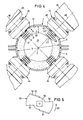
- a plurality of — in the present case four — cutting devices 44 are arranged in a common radial plane 43 to the central longitudinal axis 2. As can be seen in FIG. 4, they are each arranged at equal angular intervals, for example 90 °, and offset because of the separation of the housing 1 in a horizontal plane to this plane.
- Each cutting device 44 has an electric motor 45 which is screwed to a holder 46 which is attached to the housing 1 and passes through it.
- the holder 46 is penetrated by a knife shaft 47 driven by the electric motor 45, which is directed radially into the interior 21.
- the axes 48 of the knife shafts 47 thus lie in the radial plane 43 and intersect the axis 2.
- a plurality of knives 49, 50 are attached to each knife shaft 47 at an axial distance - based on the axes 48.
- the knives 49 are identical to one another; only the knives 50 directly adjacent to the inner wall 31 have wipers 51 bent toward the inner wall 31, by means of which material 29 which may settle between this knife 50 and the inner wall 31 is thrown back into the material ring 32.
- the axial extent e of knives 49, 50 corresponds approximately to the thickness f of the material ring 32.
- the diameter g of the knives 49 and 50 is only slightly smaller than the distance h of the mixing tools 39 which are axially adjacent to one another in this area.
- counter to the conveying direction device 27 can be brought about that the material 29 conveyed as a material ring 32 remains longer in the area of the cutting devices 44, that is to say by exerting an impulse counter to the conveying direction 27 on the material 29.
- the measures described ensure that all not very small material particles inevitably pass through a knife 49 or 50 at least once.
- the knife shafts are driven at a speed such that the peripheral speed on the outer diameter of the knives 49 and 50 is approximately 10 to 40 m / s.
- the diameter g of the knives 49.50 is approximately 50 to 250 mm, depending on the size of the mixer, ie depending on the diameter d of the interior 21 of the housing 1.
- the mixing tools 25 and 39 are designed and set in relation to the axial conveying direction 27 that, taking into account the speed of the mixer 13, an axial feed rate of the material in the mixer between 0.02 m / s and 0.2 m / s is achieved.
- a thickness f of the material ring 32 of 30 to 120 mm is used.
- the axial extent e of the knives 49, 50 in the direction of the axes 48 should be between 40 and 130 mm, so that there can be no material particles in the radially inner region of the material ring 32 that are not separated by at least one knife 49 or 50 can be detected.
- the ratio of the thickness f of the material ring 32 to the diameter d of the housing 1 is 0.06 ⁇ f / d ⁇ 0.24.
- FIG. 5 shows the shape of the knives, only the knife 50 adjacent to the inner wall 31 being shown. Starting from a hub 52, this has two cutting edges 54 leading in the direction of rotation 53 of the cutting devices 44. In the case of the knives 50, the stripper 51 is formed in each case in the region of the rear edge 55 lagging in the direction of rotation 53 by bending the flat knife 50.
- the knives 49 look exactly the same in principle; they only have no wipers.
- Materials 29 that tend to agglomerate are preferably wetted with liquid binder in the mixer. These agglomerates formed in the wetting zone b after the supply of the binder are completely dissolved by the cutting devices 44.
- paper fibers can be wetted with glue, which are then used to manufacture plasterboard.
- other materials that agglomerate after wetting can be wetted with a liquid as part of a so-called material ring mixture.
Landscapes
- Chemical & Material Sciences (AREA)
- Chemical Kinetics & Catalysis (AREA)
- Engineering & Computer Science (AREA)
- Mechanical Engineering (AREA)
- Life Sciences & Earth Sciences (AREA)
- Manufacturing & Machinery (AREA)
- Forests & Forestry (AREA)
- Wood Science & Technology (AREA)
- Mixers Of The Rotary Stirring Type (AREA)
- Processing Of Solid Wastes (AREA)
- Apparatuses For Bulk Treatment Of Fruits And Vegetables And Apparatuses For Preparing Feeds (AREA)
- Confectionery (AREA)
- Preparation Of Clay, And Manufacture Of Mixtures Containing Clay Or Cement (AREA)
- Physical Or Chemical Processes And Apparatus (AREA)
Priority Applications (1)
| Application Number | Priority Date | Filing Date | Title |
|---|---|---|---|
| AT89115813T ATE88661T1 (de) | 1988-11-24 | 1989-08-28 | Kontinuierlich arbeitender mischer. |
Applications Claiming Priority (2)
| Application Number | Priority Date | Filing Date | Title |
|---|---|---|---|
| DE3839671A DE3839671A1 (de) | 1988-11-24 | 1988-11-24 | Kontinuierlich arbeitender mischer |
| DE3839671 | 1988-11-24 |
Publications (2)
| Publication Number | Publication Date |
|---|---|
| EP0370181A1 true EP0370181A1 (fr) | 1990-05-30 |
| EP0370181B1 EP0370181B1 (fr) | 1993-04-28 |
Family
ID=6367805
Family Applications (1)
| Application Number | Title | Priority Date | Filing Date |
|---|---|---|---|
| EP89115813A Revoked EP0370181B1 (fr) | 1988-11-24 | 1989-08-28 | Mélangeur travaillant en continu |
Country Status (8)
| Country | Link |
|---|---|
| US (1) | US5018673A (fr) |
| EP (1) | EP0370181B1 (fr) |
| JP (1) | JPH02180628A (fr) |
| AT (1) | ATE88661T1 (fr) |
| BR (1) | BR8905664A (fr) |
| CA (1) | CA2003118A1 (fr) |
| DE (2) | DE3839671A1 (fr) |
| ZA (1) | ZA898730B (fr) |
Cited By (4)
| Publication number | Priority date | Publication date | Assignee | Title |
|---|---|---|---|---|
| WO1995011206A1 (fr) * | 1993-10-20 | 1995-04-27 | Universal Greening Pty Ltd | Appareil de compostage |
| EP0812616A1 (fr) * | 1996-06-11 | 1997-12-17 | Gebrüder Lödige Maschinenbaugesellschaft mbH | Dispositif pour la désagrégation des materiaux |
| WO2010081477A1 (fr) * | 2009-01-13 | 2010-07-22 | Biogasol Ipr Aps | Appareil pour le mélange rapide de milieux et procédé correspondant |
| CZ306488B6 (cs) * | 2015-12-18 | 2017-02-08 | Rudolf Ryzner | Zařízení pro máčení, míchání a obohacování organických substrátů |
Families Citing this family (29)
| Publication number | Priority date | Publication date | Assignee | Title |
|---|---|---|---|---|
| JP2696435B2 (ja) * | 1991-03-26 | 1998-01-14 | 顯治 前田 | コンクリートの混練方法及びその装置 |
| DE4124984C2 (de) * | 1991-07-27 | 1995-04-27 | Babcock Bsh Ag | Verwendung einer Misch-, Granulier- und Trocknungsvorrichtung |
| DE4132906C2 (de) * | 1991-10-04 | 1994-09-29 | Loedige Maschbau Gmbh Geb | Verwendung einer Maschine zur Gipskartonplattenwiederaufarbeitung |
| DE19503266C2 (de) * | 1995-02-02 | 2003-06-18 | Suma Sondermaschinen Gmbh | Zerkleinerungsvorrichtung zum Einbau in Rohrleitungen |
| US5580170A (en) * | 1995-10-06 | 1996-12-03 | Ferro-Tech, Inc. | Mixing and conditioning machine |
| DE19740676C2 (de) * | 1997-09-16 | 2003-07-17 | Fraunhofer Ges Forschung | Verfahren zum Beleimen von Fasern |
| ES2189557B1 (es) * | 1999-04-29 | 2004-10-16 | Ekolur, S.L. | Alimentador y mezclador de paletas para la proyeccion del hormigon o gunita y del compos. |
| US6414054B1 (en) * | 1999-12-21 | 2002-07-02 | General Electric Company | Continuous preparation of heat-vulcanizable silicone compositions |
| US6548574B1 (en) | 1999-12-21 | 2003-04-15 | General Electric Company | Heat-vulcanizable silicone compositions from premix |
| EP1157736A1 (fr) * | 2000-05-20 | 2001-11-28 | Glatt Maschinen- und Apparatebau AG | Dispositif et procédé pour le traitement quasi-continu d'un produit granulaire |
| US6511217B1 (en) * | 2000-11-03 | 2003-01-28 | General Electric Company | Method and system to compound silicone compositions |
| DE10059881B4 (de) | 2000-12-01 | 2005-06-02 | Fraunhofer-Gesellschaft zur Förderung der angewandten Forschung e.V. | Anlage zur Faseraufbereitung |
| DE10126783A1 (de) * | 2001-06-01 | 2003-01-02 | Glatt Systemtechnik Gmbh | Einrichtung zur Zuführung eines Trocknungsgases in einen Mischgranulator |
| DE10215806A1 (de) * | 2002-04-10 | 2003-10-23 | Buehler Ag | Mischer mit Durchsatzglättung |
| US7563017B1 (en) * | 2002-09-06 | 2009-07-21 | Bracegirdle Paul E | Process for mixing congealable materials such as cement, asphalt, and glue with fibers from waste carpet |
| ES2264356B1 (es) * | 2004-11-11 | 2008-01-01 | Tecnicas De Mezclado, S.L. | Aparato para la dispersion de colorantes y pigmentos en mezclas de productos pulverulentos. |
| DE102009057916B4 (de) * | 2009-05-15 | 2015-04-02 | Siempelkamp Maschinen- Und Anlagenbau Gmbh | Verfahren und Vorrichtung zum kontinuierlichen Mischen von Fasern mit einem Bindemittel |
| US9194092B2 (en) * | 2010-01-26 | 2015-11-24 | Mark Kline | Mechanism for automated mixing of liquid solutions and granular materials |
| JP2016087808A (ja) * | 2014-10-30 | 2016-05-23 | 株式会社タイガーマシン製作所 | 給材箱装置 |
| CN107921155A (zh) * | 2015-08-26 | 2018-04-17 | 株式会社佐竹 | 过热蒸汽灭菌装置 |
| US10981294B2 (en) | 2016-08-05 | 2021-04-20 | United States Gypsum Company | Headbox and forming station for fiber-reinforced cementitious panel production |
| US11224990B2 (en) * | 2016-08-05 | 2022-01-18 | United States Gypsum Company | Continuous methods of making fiber reinforced concrete panels |
| US10272399B2 (en) | 2016-08-05 | 2019-04-30 | United States Gypsum Company | Method for producing fiber reinforced cementitious slurry using a multi-stage continuous mixer |
| US11173629B2 (en) * | 2016-08-05 | 2021-11-16 | United States Gypsum Company | Continuous mixer and method of mixing reinforcing fibers with cementitious materials |
| CN109876720A (zh) * | 2017-12-06 | 2019-06-14 | 天津发洋环保科技有限公司 | 一种光触媒乳液连续生产线 |
| JP6889924B2 (ja) * | 2018-01-17 | 2021-06-18 | 株式会社切川物産 | 撹拌混合装置 |
| CN109926432A (zh) * | 2019-03-15 | 2019-06-25 | 深圳市发现环保科技有限公司 | 固体有机物细碎机 |
| CN110625814B (zh) * | 2019-09-30 | 2021-02-02 | 广州胜帆新材料科技有限公司 | 一种弧形grg板材生产用快速成型装置及方法 |
| RU2728441C1 (ru) * | 2019-10-23 | 2020-07-29 | Федеральное государственное бюджетное образовательное учреждение высшего образования "Поволжский государственный технологический университет" | Устройство для получения арболита |
Citations (8)
| Publication number | Priority date | Publication date | Assignee | Title |
|---|---|---|---|---|
| CH367379A (de) * | 1957-12-20 | 1963-02-15 | Loedige Wilhelm | Verfahren und Vorrichtung zum Mischen und Zerkleinern von pulverförmigen, feinkörnigen und faserigen Mischgütern |
| FR1511391A (fr) * | 1967-02-14 | 1968-01-26 | Appareil pour mélanger et, le cas échéant, fragmenter et/ou humecter des substances pulvérulentes, à grains fins ou fibreuses | |
| DE1432028A1 (de) * | 1964-02-18 | 1968-10-31 | Draiswerke Gmbh | Verfahren zum Betrieb von Mischmaschinen sowie zugehoerige Mischmaschine |
| US3506201A (en) * | 1965-12-17 | 1970-04-14 | Draiswerke Gmbh | Trough mixer having a dosing arrangement for mixing fibrous materials |
| DE1782585A1 (de) * | 1968-09-20 | 1971-10-14 | Draiswerke Gmbh | Mischmaschine |
| CH525702A (de) * | 1970-11-24 | 1972-07-31 | Draiswerke Gmbh | Verfahren und Vorrichtung zum kontinuierlichen Mischen bzw. Benetzen von Feststoffen mit Flüssigkeiten |
| DE2924326A1 (de) * | 1979-06-15 | 1981-01-08 | Loedige Maschbau Gmbh Geb | Verfahren zum trocknen von zum verkleben neigenden klebrigen pasten |
| DE3711987A1 (de) * | 1987-04-09 | 1988-10-27 | Durmersheim Baustoffwerke | Misch- und verteilvorrichtung fuer mischungen aus pulverigen bis koernigen feststoffen |
Family Cites Families (13)
| Publication number | Priority date | Publication date | Assignee | Title |
|---|---|---|---|---|
| DE1245577B (de) * | 1960-04-04 | 1967-07-27 | Fritz Loedige | Mischeinrichtung fuer pulverige, feinkoernige oder faserige Kunststoffe |
| DE1184325B (de) * | 1960-07-30 | 1964-12-31 | Draiswerke Gmbh | Mischmaschine |
| US3162428A (en) * | 1961-07-15 | 1964-12-22 | Loedige Wilhelm | Process for mixing and wetting solid materials |
| DE1297325B (de) * | 1966-11-03 | 1969-06-12 | Draiswerke Gmbh | Trogmischer mit einer Beduesungseinrichtung zum Mischen von faserartigen Stoffen |
| US3522934A (en) * | 1968-08-08 | 1970-08-04 | Ulrich Walter | Method and apparatus for producing a homogeneous mixture of granular and viscous substances |
| GB1307173A (en) * | 1971-07-30 | 1973-02-14 | Herfeld Kg Dr | Method of mixing materials |
| DE2240454A1 (de) * | 1972-08-17 | 1974-03-07 | Rheinstahl Ag | Vorrichtung zum zerkleinern von agglomeraten |
| US4006887A (en) * | 1974-08-13 | 1977-02-08 | Draiswerke Gmbh | Device for continuous coating of fibers |
| DE2625923A1 (de) * | 1976-06-10 | 1977-12-22 | Fritz Loedige | Vorrichtung zum mischen von fluessigkeiten |
| DE3105549A1 (de) * | 1981-02-16 | 1982-09-02 | Draiswerke Gmbh | Verfahren und vorrichtung zum beleimen von holzspaenen |
| DE3406648A1 (de) * | 1984-02-24 | 1985-09-12 | Ruberg-Mischtechnik KG, 4790 Paderborn | Mischmaschine fuer kontinuierliche mischverfahren |
| US4705222A (en) * | 1985-05-03 | 1987-11-10 | Processall, Inc. | Multipurpose mixer |
| DE3612853A1 (de) * | 1986-04-16 | 1987-11-05 | Bhs Bayerische Berg | Durchlaufmischanlage |
-
1988
- 1988-11-24 DE DE3839671A patent/DE3839671A1/de not_active Withdrawn
-
1989
- 1989-08-28 AT AT89115813T patent/ATE88661T1/de not_active IP Right Cessation
- 1989-08-28 EP EP89115813A patent/EP0370181B1/fr not_active Revoked
- 1989-08-28 DE DE8989115813T patent/DE58904203D1/de not_active Expired - Fee Related
- 1989-11-06 BR BR898905664A patent/BR8905664A/pt not_active Application Discontinuation
- 1989-11-15 ZA ZA898730A patent/ZA898730B/xx unknown
- 1989-11-15 JP JP1295147A patent/JPH02180628A/ja active Pending
- 1989-11-16 CA CA002003118A patent/CA2003118A1/fr not_active Abandoned
- 1989-11-20 US US07/438,271 patent/US5018673A/en not_active Expired - Fee Related
Patent Citations (8)
| Publication number | Priority date | Publication date | Assignee | Title |
|---|---|---|---|---|
| CH367379A (de) * | 1957-12-20 | 1963-02-15 | Loedige Wilhelm | Verfahren und Vorrichtung zum Mischen und Zerkleinern von pulverförmigen, feinkörnigen und faserigen Mischgütern |
| DE1432028A1 (de) * | 1964-02-18 | 1968-10-31 | Draiswerke Gmbh | Verfahren zum Betrieb von Mischmaschinen sowie zugehoerige Mischmaschine |
| US3506201A (en) * | 1965-12-17 | 1970-04-14 | Draiswerke Gmbh | Trough mixer having a dosing arrangement for mixing fibrous materials |
| FR1511391A (fr) * | 1967-02-14 | 1968-01-26 | Appareil pour mélanger et, le cas échéant, fragmenter et/ou humecter des substances pulvérulentes, à grains fins ou fibreuses | |
| DE1782585A1 (de) * | 1968-09-20 | 1971-10-14 | Draiswerke Gmbh | Mischmaschine |
| CH525702A (de) * | 1970-11-24 | 1972-07-31 | Draiswerke Gmbh | Verfahren und Vorrichtung zum kontinuierlichen Mischen bzw. Benetzen von Feststoffen mit Flüssigkeiten |
| DE2924326A1 (de) * | 1979-06-15 | 1981-01-08 | Loedige Maschbau Gmbh Geb | Verfahren zum trocknen von zum verkleben neigenden klebrigen pasten |
| DE3711987A1 (de) * | 1987-04-09 | 1988-10-27 | Durmersheim Baustoffwerke | Misch- und verteilvorrichtung fuer mischungen aus pulverigen bis koernigen feststoffen |
Cited By (9)
| Publication number | Priority date | Publication date | Assignee | Title |
|---|---|---|---|---|
| WO1995011206A1 (fr) * | 1993-10-20 | 1995-04-27 | Universal Greening Pty Ltd | Appareil de compostage |
| EP0812616A1 (fr) * | 1996-06-11 | 1997-12-17 | Gebrüder Lödige Maschinenbaugesellschaft mbH | Dispositif pour la désagrégation des materiaux |
| US5803374A (en) * | 1996-06-11 | 1998-09-08 | Gebrueder Loedige Maschinenbaugesellschaft Mbh | Breakdown tool |
| WO2010081477A1 (fr) * | 2009-01-13 | 2010-07-22 | Biogasol Ipr Aps | Appareil pour le mélange rapide de milieux et procédé correspondant |
| AU2010205966B2 (en) * | 2009-01-13 | 2014-06-05 | Biogasol Aps | Apparatus for rapid mixing of media and method |
| CN102271792B (zh) * | 2009-01-13 | 2014-09-17 | 拜格索有限公司 | 快速混合介质的装置及方法 |
| US8845976B2 (en) | 2009-01-13 | 2014-09-30 | Biogasol Aps | Apparatus for rapid mixing of media and method |
| US9605223B2 (en) | 2009-01-13 | 2017-03-28 | Biogasol Aps | Apparatus for rapid mixing of media and method |
| CZ306488B6 (cs) * | 2015-12-18 | 2017-02-08 | Rudolf Ryzner | Zařízení pro máčení, míchání a obohacování organických substrátů |
Also Published As
| Publication number | Publication date |
|---|---|
| DE3839671A1 (de) | 1990-05-31 |
| US5018673A (en) | 1991-05-28 |
| CA2003118A1 (fr) | 1990-05-24 |
| ATE88661T1 (de) | 1993-05-15 |
| DE58904203D1 (de) | 1993-06-03 |
| ZA898730B (en) | 1990-08-29 |
| EP0370181B1 (fr) | 1993-04-28 |
| JPH02180628A (ja) | 1990-07-13 |
| BR8905664A (pt) | 1990-06-05 |
Similar Documents
| Publication | Publication Date | Title |
|---|---|---|
| EP0370181B1 (fr) | Mélangeur travaillant en continu | |
| DE3532722C2 (fr) | ||
| DE2709309C3 (de) | Vorrichtung zum Austragen von fließfähigem Gut | |
| DE2624048C2 (de) | Kontinuierliche Durchgangsmischvorrichtung | |
| DE2702033C2 (de) | Vorrichtung zum kontinuierlichen Zumischen von Zusatzmaterial zu einem Strom aus rieselfähigem Grundmaterial | |
| EP0046569A2 (fr) | Procédé et appareil pour mélanger des solides avec des liquides | |
| DE2600648A1 (de) | Pelletpresse | |
| DE661846C (de) | Vorrichtung zum Mischen, Ruehren, Aufloesen, Eindicken, Kneten, Verreiben, Zerkleinern oder Versalben von fliessfaehigen oder bereits pulverfoermigen Massen, vorzugsweise zum Bearbeiten von Kakao- oder Schokolademassen | |
| EP0304604B1 (fr) | Mélangeur avec agitateur et broyeur | |
| DE2924317C2 (de) | Zweistufige Strangpreßvorrichtung für thermoplastische Formmassen, insbesondere für pulverförmige Kunststoffe | |
| DE2453810A1 (de) | Verfahren und vorrichtung zum dispergieren eines pulvers in einer fluessigkeit | |
| EP0716878B1 (fr) | Dispositif de fabrication de peinture | |
| DE2456613B1 (de) | Einrichtung zum kontinuierlichen aufbereiten von koernigem material | |
| DE2438818A1 (de) | Vorrichtung zum kontinuierlichen beleimen von fasern | |
| DE2219352C2 (de) | Kontinuierlich arbeitender Ringmischer | |
| EP0211230B1 (fr) | Dispositif pour mélanger des matériaux solides et des liquides | |
| DE4131587A1 (de) | Verfahren und vorrichtung zur wiederaufbereitung von altreifen | |
| EP0587058A1 (fr) | Dispositif de remplissage notamment pour sacs à soupape | |
| DE3406648C2 (fr) | ||
| DE2831641C2 (de) | Vorrichtung zum Zerkleinern von feuchter Abfallmasse | |
| DE2736812C2 (fr) | ||
| DE2511971C3 (de) | Verfahren zum Herstellen von Zusatzstoffe enthaltenden Polyvinylchlorid-Mischungen | |
| EP0036985B1 (fr) | Dispositif pour obtenir un mélange d'au moins un composant solide pétrissable en morceaux et d'au moins un composant liquide | |
| EP1043061B1 (fr) | Dispositif de dispersion | |
| DE3401804A1 (de) | Dosiervorrichtung fuer schuettbare materialien, insbesondere pulverfoermige oder koernige materialien |
Legal Events
| Date | Code | Title | Description |
|---|---|---|---|
| PUAI | Public reference made under article 153(3) epc to a published international application that has entered the european phase |
Free format text: ORIGINAL CODE: 0009012 |
|
| AK | Designated contracting states |
Kind code of ref document: A1 Designated state(s): AT BE CH DE ES FR GB IT LI NL SE |
|
| 17P | Request for examination filed |
Effective date: 19901119 |
|
| 17Q | First examination report despatched |
Effective date: 19920324 |
|
| GRAA | (expected) grant |
Free format text: ORIGINAL CODE: 0009210 |
|
| AK | Designated contracting states |
Kind code of ref document: B1 Designated state(s): AT BE CH DE ES FR GB IT LI NL SE |
|
| PG25 | Lapsed in a contracting state [announced via postgrant information from national office to epo] |
Ref country code: IT Free format text: LAPSE BECAUSE OF FAILURE TO SUBMIT A TRANSLATION OF THE DESCRIPTION OR TO PAY THE FEE WITHIN THE PRE;WARNING: LAPSES OF ITALIAN PATENTS WITH EFFECTIVE DATE BEFORE 2007 MAY HAVE OCCURRED AT ANY TIME BEFORE 2007. THE CORRECT EFFECTIVE DATE MAY BE DIFFERENT FROM THE ONE RECORDED.SCRIBED TIME-LIMIT Effective date: 19930428 Ref country code: FR Effective date: 19930428 Ref country code: GB Effective date: 19930428 Ref country code: NL Effective date: 19930428 Ref country code: BE Effective date: 19930428 Ref country code: SE Effective date: 19930428 |
|
| REF | Corresponds to: |
Ref document number: 88661 Country of ref document: AT Date of ref document: 19930515 Kind code of ref document: T |
|
| REF | Corresponds to: |
Ref document number: 58904203 Country of ref document: DE Date of ref document: 19930603 |
|
| PG25 | Lapsed in a contracting state [announced via postgrant information from national office to epo] |
Ref country code: ES Free format text: LAPSE BECAUSE OF FAILURE TO SUBMIT A TRANSLATION OF THE DESCRIPTION OR TO PAY THE FEE WITHIN THE PRESCRIBED TIME-LIMIT Effective date: 19930729 |
|
| EN | Fr: translation not filed | ||
| NLV1 | Nl: lapsed or annulled due to failure to fulfill the requirements of art. 29p and 29m of the patents act | ||
| GBV | Gb: ep patent (uk) treated as always having been void in accordance with gb section 77(7)/1977 [no translation filed] |
Effective date: 19930428 |
|
| PLBI | Opposition filed |
Free format text: ORIGINAL CODE: 0009260 |
|
| 26 | Opposition filed |
Opponent name: GEBR. LOEDIGE MASCHINENBAU-GESELLSCHAFT MBH Effective date: 19940126 |
|
| PGFP | Annual fee paid to national office [announced via postgrant information from national office to epo] |
Ref country code: AT Payment date: 19960723 Year of fee payment: 8 Ref country code: CH Payment date: 19960723 Year of fee payment: 8 |
|
| PGFP | Annual fee paid to national office [announced via postgrant information from national office to epo] |
Ref country code: DE Payment date: 19961023 Year of fee payment: 8 |
|
| PG25 | Lapsed in a contracting state [announced via postgrant information from national office to epo] |
Ref country code: AT Free format text: LAPSE BECAUSE OF NON-PAYMENT OF DUE FEES Effective date: 19970828 |
|
| PG25 | Lapsed in a contracting state [announced via postgrant information from national office to epo] |
Ref country code: LI Free format text: LAPSE BECAUSE OF NON-PAYMENT OF DUE FEES Effective date: 19970831 Ref country code: CH Free format text: LAPSE BECAUSE OF NON-PAYMENT OF DUE FEES Effective date: 19970831 |
|
| APAE | Appeal reference modified |
Free format text: ORIGINAL CODE: EPIDOS REFNO |
|
| REG | Reference to a national code |
Ref country code: CH Ref legal event code: PL |
|
| PG25 | Lapsed in a contracting state [announced via postgrant information from national office to epo] |
Ref country code: DE Free format text: LAPSE BECAUSE OF NON-PAYMENT OF DUE FEES Effective date: 19980501 |
|
| APAC | Appeal dossier modified |
Free format text: ORIGINAL CODE: EPIDOS NOAPO |
|
| RDAH | Patent revoked |
Free format text: ORIGINAL CODE: EPIDOS REVO |
|
| RDAG | Patent revoked |
Free format text: ORIGINAL CODE: 0009271 |
|
| STAA | Information on the status of an ep patent application or granted ep patent |
Free format text: STATUS: PATENT REVOKED |
|
| 27W | Patent revoked |
Effective date: 19981229 |
|
| APAH | Appeal reference modified |
Free format text: ORIGINAL CODE: EPIDOSCREFNO |