EP0370390A2 - Appareil pour la formation d'images numériques - Google Patents
Appareil pour la formation d'images numériques Download PDFInfo
- Publication number
- EP0370390A2 EP0370390A2 EP89121221A EP89121221A EP0370390A2 EP 0370390 A2 EP0370390 A2 EP 0370390A2 EP 89121221 A EP89121221 A EP 89121221A EP 89121221 A EP89121221 A EP 89121221A EP 0370390 A2 EP0370390 A2 EP 0370390A2
- Authority
- EP
- European Patent Office
- Prior art keywords
- image forming
- drive motor
- forming equipment
- polygon motor
- rotation
- Prior art date
- Legal status (The legal status is an assumption and is not a legal conclusion. Google has not performed a legal analysis and makes no representation as to the accuracy of the status listed.)
- Withdrawn
Links
- 238000013459 approach Methods 0.000 abstract description 6
- 238000001514 detection method Methods 0.000 description 9
- 230000003287 optical effect Effects 0.000 description 8
- 238000011017 operating method Methods 0.000 description 5
- 230000004044 response Effects 0.000 description 4
- 238000012986 modification Methods 0.000 description 2
- 230000004048 modification Effects 0.000 description 2
- 238000012545 processing Methods 0.000 description 2
- 238000012546 transfer Methods 0.000 description 2
- 230000003247 decreasing effect Effects 0.000 description 1
- 238000011161 development Methods 0.000 description 1
Images


Classifications
-
- H—ELECTRICITY
- H04—ELECTRIC COMMUNICATION TECHNIQUE
- H04N—PICTORIAL COMMUNICATION, e.g. TELEVISION
- H04N1/00—Scanning, transmission or reproduction of documents or the like, e.g. facsimile transmission; Details thereof
- H04N1/04—Scanning arrangements, i.e. arrangements for the displacement of active reading or reproducing elements relative to the original or reproducing medium, or vice versa
- H04N1/047—Detection, control or error compensation of scanning velocity or position
- H04N1/053—Detection, control or error compensation of scanning velocity or position in main scanning direction, e.g. synchronisation of line start or picture elements in a line
-
- H—ELECTRICITY
- H04—ELECTRIC COMMUNICATION TECHNIQUE
- H04N—PICTORIAL COMMUNICATION, e.g. TELEVISION
- H04N1/00—Scanning, transmission or reproduction of documents or the like, e.g. facsimile transmission; Details thereof
- H04N1/04—Scanning arrangements, i.e. arrangements for the displacement of active reading or reproducing elements relative to the original or reproducing medium, or vice versa
- H04N1/113—Scanning arrangements, i.e. arrangements for the displacement of active reading or reproducing elements relative to the original or reproducing medium, or vice versa using oscillating or rotating mirrors
-
- H—ELECTRICITY
- H04—ELECTRIC COMMUNICATION TECHNIQUE
- H04N—PICTORIAL COMMUNICATION, e.g. TELEVISION
- H04N2201/00—Indexing scheme relating to scanning, transmission or reproduction of documents or the like, and to details thereof
- H04N2201/04—Scanning arrangements
- H04N2201/047—Detection, control or error compensation of scanning velocity or position
- H04N2201/04753—Control or error compensation of scanning position or velocity
- H04N2201/04755—Control or error compensation of scanning position or velocity by controlling the position or movement of a scanning element or carriage, e.g. of a polygonal mirror, of a drive motor
Definitions
- the present invention relates to a digital image forming equipment in which image is formed by reflecting and scanning laser light emitted from a source of light onto a photosensitive body by means of a polygon mirror driven by a drive motor (so-called a polygon motor).
- laser light is irradiated on the surface of a photosensitive drum on the basis of information of copy images which have been digitally signalized, thereby causing electrostatic latent images to be formed.
- the above laser light which is emitted from the source of light is reflected and scanned onto the surface of a photosensitive drum by means of a polygon mirror rotated by a polygon motor.
- the above polygon motor usually rotates at such a high speed as 5,000 to 20,000 rpm. and is requested to rotate at a stabilized condition since high precision is required for scanning the laser light. As it usually takes about 5 seconds from start of the rotation of the above polygon motor to reaching the stabilized rotation condition, conventionally the polygon motor starts to rotate as soon as the power source of a copying machine is turned on, and it is so controlled that it can usually consecutively rotate while waiting unless the power source is turned off. Quick response for copying jobs by an operator have been thus secured.
- a very high grade of bearing such as a non-contact bearing of air gap type is required.
- a non-contact type bearing as shown in the above becomes so complicated in structure and the price thereof may become comparatively high.
- the polygon motor rotates at a high speed, rotary noise whose frequency is comparatively high is emitted in accompanying with the rotation of the polygon motor.
- the above rotary noise is continuously emitted for a longer period of time since the above polygon motor consecutively rotates, thereby causing another problem to occur. That is, the polygon motor gives a sense of uncomfortable feeling to every person who is in the vicinity of the copying machine.
- a digital image forming equipment in which image is formed by reflecting and scanning laser light emitted from a source of light onto a photosensitive body by means of a polygon mirror driven and rotated by a drive motor comprises; means for starting the rotation of a drive motor when operating the operating portions provided in the body of the above image forming equipment, and means for stopping the rotation of the drive motor in a specified period of time after the termination of image forming operation.
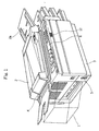
- a digital copying machine of this preferred embodiment has almost the same appearance as that of the conventional digital copying machine.
- a detection switch for detecting whether or not a document exists is placed on a document set portion 2a of a automatic document feeding unit 2 which has a sorter 1.
- the above automatic document feeding unit 2 is so placed that it can be opened and closed against the copying machine proper 3, and a document pusher mat (not illustrated) is mounted at the lower side of this automatic document feeding unit 2.
- An opening and closing detection switch 4 is so arranged at the position which confronts to the lower surface of the above automatic document feeding unit 2 on the above copying machine proper 3 that it can detect opening or closing of the above document pusher mat. A state that a document is placed on the upper surface of the ducument set plate is indirectly detected by ON or OFF of the above opening and closing detection switch in.
- a power switch 5, and an operation panel 6 are shown in Fig. 1.
- Various kinds of operating switches such as a number-of-copies setting switch, a selector switch for paper size, a sorter actuation switch and a start switch are arranged on the operation panel 6.
- the operating portion consists of the above opening and closing detection switch 4, a detection switch for a document on the document set portion 2a and various kinds of switches on the operation panel 6.
- a polygon mirror 7 (Refer to Fig.2) for reflecting laser light emitted from the source of light and scanning the same on the photosensitive drum, a polygon motor 8 (a drive motor) to drive and rotate this polygon mirror 7 at a high speed and an optical system unit 9 to read the image of a document placed on the document set plate.
- a printer unit 10 which comprises a development section to develop electrostatic latent image formed on the above photosensitive drum, a transfer section to transfer the above copy image to a copying sheet of paper and a fixing section of the above image on the copying sheet of paper are arranged in the lower part of the above copying machine 3.
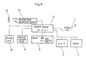
- the above sorter 1, automatic document feeding unit 2, polygon motor 8, optical system unit 9 and printer unit 10 are controlled by a control board 11 in accordance with the signals coming from various kinds of operating switches located in the above operation panel 6, the opening and closing detection switch 4 and the document detection switch.
- the above control board 11 comprises a CPU, memory means and interfaces.
- means for starting the rotation of the polygon motor is so composed that the above polygon motor 8 can begin to rotate when the above operating portions are operated in the steps of S1, S2, S3 and S4.
- step S7 in the case that it is judged that the polygon motor 8 has reached the high speed stabilized state, the sorter 1, the automatic document feeding unit 2, and the printer unit 10 are driven by control signals coming from the control board 11, thereby causing copying operation to be conducted (S8).
- step S8 The copying operation in the above step S8 is continued until it is judged that the copying operation of the number of times corresponding to the number of copies preset in the step S9 has been terminated.
- means for stopping the rotation of the polygon motor 8 is so composed that the stopping means can stop the rotation of the polygon motor 8 when the specified period of time has elapsed after the copying operation has been terminated in the above steps S10 and S11.
- the polygon motor not to be caused to rotate at all times, taking quick response for the copying operation by an operator into consideration.
- the drive motor can begin to rotate when an operator operates the operating portion.
- the image forming equipment may be so composed that the drive motor can begin to rotate when an operator approaches the image forming equipment.
- the example of this composition is shown with regard to Fig. 4 and Fig. 5.
- Fig. 4 is a block diagrammatic view of the above digital copying machine.
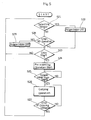
- Fig.5 is a flow chart showing the operating procedure of the digital copying machine.
- the digital copying machine of this example is of almost the same in appearance as that of the conventional digital copying machine.
- a human body detecting sensor 12 (detecting means) is provided at the front side of the above copying machine proper 3 in the digital copying machine of this example.
- the above human body detecting sensor 12 can detect existence of an operator 13 (Refer to Fig. 4) who approaches the copying machine proper 3.
- an ultrasonic wave sensor or an infrared ray sensor may be used as a detecting sensor.
- the other components for example, a polygon mirror 7, a polygon motor 8, an optical system unit 9, a printer unit 10, etc. are so arranged in the same manner as the above preferred embodiment.
- means for starting the rotation of the polygon motor 8 is so composed that the means can start the rotation of the polygon motor 8 on the basis of changes of the state of output signal from the human body detecting sensor 12 in the steps S1 and S2.
- pre-scanning operation of the above optical system unit 9 is started (S24).
- the polygon motor 8 reaches the high speed stabilized state as a specified period of time elapses until the operator 13 approaches the copying machine 3 and begins operating and while the pre-scanning operation of the optical system unit 9 is being conducted in the step S24 and the operator 13 is operating the other operating switches.
- step S26 The copying operation in the above step S26 is continued until it is judged that the copying operation of the number of times corresponding to the number of copies preset in the step S27 has been terminated.
- the time until an operator starts the operation after approaching the copying machine 3 and the processing time necessary in the steps S23 and S24 can be effectively utilized as stand-by time of the polygon motor 8.
- the polygon motor 8 stops rotating (S29).
- means for stopping the rotation of the polygon motor 8 is so composed that the stopping means can stop the rotation of the polygon motor 8 when the specified period of time has elapsed after the copying operation has been terminated in the above steps S28 and S29.
- the polygon motor not to be caused to rotate at all times, taking quick response for the copying operation by an operator into consideration.
- a human body detecting sensor 12 of this embodiment may be installed at a side of the copying machine proper 3 or a plurality of the detecting sensors 12 may be provided. Furthermore, the above human body detecting sensor 12 can be provided apart from the copying machine proper 3.
Landscapes
- Engineering & Computer Science (AREA)
- Multimedia (AREA)
- Signal Processing (AREA)
- Mechanical Optical Scanning Systems (AREA)
- Control Or Security For Electrophotography (AREA)
- Laser Beam Printer (AREA)
Applications Claiming Priority (4)
| Application Number | Priority Date | Filing Date | Title |
|---|---|---|---|
| JP295523/88 | 1988-11-22 | ||
| JP295522/88 | 1988-11-22 | ||
| JP63295522A JPH02141770A (ja) | 1988-11-22 | 1988-11-22 | デジタル画像形成装置 |
| JP63295523A JPH02141771A (ja) | 1988-11-22 | 1988-11-22 | デジタル画像形成装置 |
Publications (2)
| Publication Number | Publication Date |
|---|---|
| EP0370390A2 true EP0370390A2 (fr) | 1990-05-30 |
| EP0370390A3 EP0370390A3 (fr) | 1991-07-31 |
Family
ID=26560307
Family Applications (1)
| Application Number | Title | Priority Date | Filing Date |
|---|---|---|---|
| EP19890121221 Withdrawn EP0370390A3 (fr) | 1988-11-22 | 1989-11-16 | Appareil pour la formation d'images numériques |
Country Status (2)
| Country | Link |
|---|---|
| US (1) | US5107279A (fr) |
| EP (1) | EP0370390A3 (fr) |
Cited By (1)
| Publication number | Priority date | Publication date | Assignee | Title |
|---|---|---|---|---|
| US9794446B2 (en) * | 2016-03-11 | 2017-10-17 | Fuji Xerox Co., Ltd. | Information processing apparatus, information processing method, and non-transitory computer readable medium |
Families Citing this family (10)
| Publication number | Priority date | Publication date | Assignee | Title |
|---|---|---|---|---|
| JPH03129367A (ja) * | 1989-10-14 | 1991-06-03 | Canon Inc | レーザビームプリンタ |
| JPH06189048A (ja) * | 1992-09-14 | 1994-07-08 | Ricoh Co Ltd | 操作表示用制御装置、画像形成装置及び電源投入用制御装置 |
| JP3574223B2 (ja) * | 1995-05-24 | 2004-10-06 | セイコーエプソン株式会社 | プリンタにおける印字開始方法 |
| JPH0983750A (ja) * | 1995-09-20 | 1997-03-28 | Toshiba Corp | 画像形成装置およびその制御方法 |
| JP3675063B2 (ja) * | 1996-10-15 | 2005-07-27 | ブラザー工業株式会社 | 画像読み取りシステム及び画像読み取り方法 |
| JPH10142857A (ja) * | 1996-11-08 | 1998-05-29 | Ricoh Co Ltd | 画像形成装置 |
| JP2000078351A (ja) * | 1998-08-28 | 2000-03-14 | Minolta Co Ltd | 画像読み取り装置 |
| JP6360378B2 (ja) * | 2014-07-15 | 2018-07-18 | キヤノン株式会社 | 画像形成装置 |
| JP2017181561A (ja) | 2016-03-28 | 2017-10-05 | キヤノン株式会社 | 画像形成装置 |
| JP2020008691A (ja) | 2018-07-06 | 2020-01-16 | キヤノン株式会社 | 画像形成装置及びその制御方法 |
Family Cites Families (2)
| Publication number | Priority date | Publication date | Assignee | Title |
|---|---|---|---|---|
| JPH0612382B2 (ja) * | 1984-02-15 | 1994-02-16 | キヤノン株式会社 | レ−ザビ−ムプリンタ |
| US4933772A (en) * | 1985-10-07 | 1990-06-12 | Minolta Camera Kabushiki Kaisha | Electrophotographic printer with improved timing arrangements |
-
1989
- 1989-11-16 EP EP19890121221 patent/EP0370390A3/fr not_active Withdrawn
-
1991
- 1991-07-05 US US07/728,036 patent/US5107279A/en not_active Expired - Fee Related
Cited By (1)
| Publication number | Priority date | Publication date | Assignee | Title |
|---|---|---|---|---|
| US9794446B2 (en) * | 2016-03-11 | 2017-10-17 | Fuji Xerox Co., Ltd. | Information processing apparatus, information processing method, and non-transitory computer readable medium |
Also Published As
| Publication number | Publication date |
|---|---|
| US5107279A (en) | 1992-04-21 |
| EP0370390A3 (fr) | 1991-07-31 |
Similar Documents
| Publication | Publication Date | Title |
|---|---|---|
| US4540269A (en) | Opening detecting device of a copy document cover suitable for electrophotographic copying machine | |
| US5107279A (en) | Digital image forming equipment | |
| US4696562A (en) | Multifunctional copying machine | |
| US4809025A (en) | Recording apparatus | |
| JPH03230971A (ja) | レーザビーム作像装置 | |
| JPH04156567A (ja) | 画像形成装置 | |
| JP2000206851A (ja) | 画像形成装置 | |
| JP2007312379A (ja) | 画像形成装置及びその制御方法 | |
| US5610652A (en) | Electrophotographic image recording apparatus | |
| JPH0895461A (ja) | 画像形成装置 | |
| JP2001169027A (ja) | 画像読取装置およびこれを使用した画像形成装置 | |
| JP2898989B2 (ja) | 記録装置 | |
| JPH0575801A (ja) | デジタル複写機 | |
| JPH02141770A (ja) | デジタル画像形成装置 | |
| JPH02141771A (ja) | デジタル画像形成装置 | |
| JPH1184549A (ja) | 複写機の原稿サイズ検知装置 | |
| JP3059231B2 (ja) | デジタル複写機 | |
| JP2745509B2 (ja) | スキャナモータのレディ状態検出装置 | |
| JPS5923965A (ja) | 記録装置 | |
| JP2744286B2 (ja) | 原稿サイズ・位置検知装置 | |
| JP3248357B2 (ja) | 原稿読み取り装置 | |
| JPS6295553A (ja) | 画像形成装置 | |
| JP2664225B2 (ja) | 原稿サイズ検出装置 | |
| JPS6298342A (ja) | 複写機 | |
| JP2621051B2 (ja) | 原稿サイズ検出装置 |
Legal Events
| Date | Code | Title | Description |
|---|---|---|---|
| PUAI | Public reference made under article 153(3) epc to a published international application that has entered the european phase |
Free format text: ORIGINAL CODE: 0009012 |
|
| 17P | Request for examination filed |
Effective date: 19891211 |
|
| AK | Designated contracting states |
Kind code of ref document: A2 Designated state(s): DE FR GB NL |
|
| PUAL | Search report despatched |
Free format text: ORIGINAL CODE: 0009013 |
|
| AK | Designated contracting states |
Kind code of ref document: A3 Designated state(s): DE FR GB NL |
|
| 17Q | First examination report despatched |
Effective date: 19931018 |
|
| STAA | Information on the status of an ep patent application or granted ep patent |
Free format text: STATUS: THE APPLICATION IS DEEMED TO BE WITHDRAWN |
|
| 18D | Application deemed to be withdrawn |
Effective date: 19940301 |