EP0370416A2 - Architecture pour mémoire EPROM à effacement éclair - Google Patents
Architecture pour mémoire EPROM à effacement éclair Download PDFInfo
- Publication number
- EP0370416A2 EP0370416A2 EP89121391A EP89121391A EP0370416A2 EP 0370416 A2 EP0370416 A2 EP 0370416A2 EP 89121391 A EP89121391 A EP 89121391A EP 89121391 A EP89121391 A EP 89121391A EP 0370416 A2 EP0370416 A2 EP 0370416A2
- Authority
- EP
- European Patent Office
- Prior art keywords
- region
- drain
- source
- gate electrode
- floating gate
- Prior art date
- Legal status (The legal status is an assumption and is not a legal conclusion. Google has not performed a legal analysis and makes no representation as to the accuracy of the status listed.)
- Withdrawn
Links
Images


Classifications
-
- G—PHYSICS
- G11—INFORMATION STORAGE
- G11C—STATIC STORES
- G11C17/00—Read-only memories programmable only once; Semi-permanent stores, e.g. manually-replaceable information cards
-
- G—PHYSICS
- G11—INFORMATION STORAGE
- G11C—STATIC STORES
- G11C16/00—Erasable programmable read-only memories
- G11C16/02—Erasable programmable read-only memories electrically programmable
- G11C16/06—Auxiliary circuits, e.g. for writing into memory
- G11C16/34—Determination of programming status, e.g. threshold voltage, overprogramming or underprogramming, retention
- G11C16/3418—Disturbance prevention or evaluation; Refreshing of disturbed memory data
- G11C16/3427—Circuits or methods to prevent or reduce disturbance of the state of a memory cell when neighbouring cells are read or written
-
- G—PHYSICS
- G11—INFORMATION STORAGE
- G11C—STATIC STORES
- G11C16/00—Erasable programmable read-only memories
- G11C16/02—Erasable programmable read-only memories electrically programmable
- G11C16/06—Auxiliary circuits, e.g. for writing into memory
- G11C16/26—Sensing or reading circuits; Data output circuits
-
- G—PHYSICS
- G11—INFORMATION STORAGE
- G11C—STATIC STORES
- G11C16/00—Erasable programmable read-only memories
- G11C16/02—Erasable programmable read-only memories electrically programmable
- G11C16/06—Auxiliary circuits, e.g. for writing into memory
- G11C16/34—Determination of programming status, e.g. threshold voltage, overprogramming or underprogramming, retention
- G11C16/3418—Disturbance prevention or evaluation; Refreshing of disturbed memory data
-
- H—ELECTRICITY
- H10—SEMICONDUCTOR DEVICES; ELECTRIC SOLID-STATE DEVICES NOT OTHERWISE PROVIDED FOR
- H10D—INORGANIC ELECTRIC SEMICONDUCTOR DEVICES
- H10D30/00—Field-effect transistors [FET]
- H10D30/60—Insulated-gate field-effect transistors [IGFET]
- H10D30/68—Floating-gate IGFETs
- H10D30/681—Floating-gate IGFETs having only two programming levels
- H10D30/683—Floating-gate IGFETs having only two programming levels programmed by tunnelling of carriers, e.g. Fowler-Nordheim tunnelling
-
- H—ELECTRICITY
- H10—SEMICONDUCTOR DEVICES; ELECTRIC SOLID-STATE DEVICES NOT OTHERWISE PROVIDED FOR
- H10D—INORGANIC ELECTRIC SEMICONDUCTOR DEVICES
- H10D30/00—Field-effect transistors [FET]
- H10D30/60—Insulated-gate field-effect transistors [IGFET]
- H10D30/68—Floating-gate IGFETs
- H10D30/681—Floating-gate IGFETs having only two programming levels
- H10D30/684—Floating-gate IGFETs having only two programming levels programmed by hot carrier injection
-
- Y—GENERAL TAGGING OF NEW TECHNOLOGICAL DEVELOPMENTS; GENERAL TAGGING OF CROSS-SECTIONAL TECHNOLOGIES SPANNING OVER SEVERAL SECTIONS OF THE IPC; TECHNICAL SUBJECTS COVERED BY FORMER USPC CROSS-REFERENCE ART COLLECTIONS [XRACs] AND DIGESTS
- Y10—TECHNICAL SUBJECTS COVERED BY FORMER USPC
- Y10S—TECHNICAL SUBJECTS COVERED BY FORMER USPC CROSS-REFERENCE ART COLLECTIONS [XRACs] AND DIGESTS
- Y10S257/00—Active solid-state devices, e.g. transistors, solid-state diodes
- Y10S257/906—Dram with capacitor electrodes used for accessing, e.g. bit line is capacitor plate
Definitions
- This invention pertains to memory devices and more particularly to flash erase EEPROM memories.
- EEPROMs Electrically erasable programmable read only memories
- EEPROMs like other memory devices, include a plurality of memory cells, each capable of storing a single binary digit (bit).
- the binary value stored in each cell is programmed to a logical zero or logical one value by placing an appropriate charge on the floating gate of a MOS transistor forming the cell.
- the threshold voltage required to be applied to the control gate of the floating gate transistor is changed to either a voltage level representing a logical one or a voltage level representing a logical zero.
- a voltage is applied to the control gate which is greater than the threshold voltage associated with a logical one but less than the threshold voltage associated with a logical zero.
- the floating gate transistor turns on if it stores a logical one, but remains off if it stores a logical zero.
- a sense amplifier well known in the art, is used to determine if the transistor is on or off.
- FIGURE 1 is a schematic diagram of a typical prior art EEPROM.
- the circuit of Figure 1 allows for flash erasure of all bits stored in the memory array, that is to say the cells are written on a bit-by-bit, or word-by-word basis, the array is read on a word-by-word basis, and the array is erased by erasing all cells simultaneously to the logical one state.
- flash erase EEPROM circuit 100 includes a plurality of row lines 101-1 through 101-N, and a plurality of columns or "bit lines" 102-1 through 102-M. Associated with each combination of row line and bit line is one of floating gate memory cell transistors 105-1-1 through 105-N-M.
- each memory cell transistor 105-1-1 through 105-N-M are connected to their associated row lines 101-1 through 101-N.
- the drains of each memory cell transistor are connected to their associated bit lines.
- the sources of each memory cell transistor are connected in common to the drain of erase transistor 112, as is more fully described later.
- Power is supplied to each bit line 102-1 through 102-M through column select transistors 104-1 through 104-M, each receiving an appropriate column select signal on their gate leads 103-1 through 103-M, respectively.
- the entire block of array transistors 105-1-1 through 105-N-M is selected by block transistor 106 receiving a block select signal (for example, a decoded signal based on one or more most significant address bits, with the least significant address bits defining individual memory cells within the block) applied to its gate lead 107.
- a block select signal for example, a decoded signal based on one or more most significant address bits, with the least significant address bits defining individual memory cells within the block
- block select transistor 106 When block select transistor 106 is turned on, the block containing memory cells 105-1-1 through 105-N-M is selected and when one or more column select transistors 104-1 through 104-M are turned on, desired ones of bit lines 102-1 through 102-M are selected. This enables the appropriate voltages to be applied to desired ones
- a programming voltage VPP (typically 12 volts during programming and 17 volts during erasure) is selectively applied to selected bit lines when programming/erase control circuitry 119 provides a signal to the gate of programming/erase transistor 108 causing transistor 108 to conduct.
- VPP programming voltage
- the voltage level of a selected bit line is applied via transistor 110 to sense amplifier 111 in order to determine the value of the bit stored in a selected memory cell.
- circuit 100 in the programming, reading, and erasure modes is depicted in Table 1.
- memory array transistors are written individually by selectively addressing desired rows and columns.
- a selected row receives a voltage (typically approximately 14 volts) thereby enabling the memory transistors within the row to turn on.
- deselected rows each receive a logical zero, preventing the memory transistors of the deselected rows from turning on.
- their associated bit lines receive a logical zero by causing their associated column select transistors 104-1 through 104-M to remain off.
- columns whose memory cells are to store a logical one are deselected.
- columns associated with memory cells which are to store a logical zero are selected by turning on their associated column select transistors 104-1 through 104-M, and programming/erase control circuitry 119 causes transistor 108 to turn on, thereby applying programming voltage VPP to the selected columns.
- This action causes the memory transistors which are to store a logical one to turn on and, with a relatively high voltage VPP applied to their drains, 0 volts on their sources, and a high voltage (typically 14 volts) applied to the control gate, cause hot electrons to be injected from the drain to the floating gate, thereby increasing the control gate threshold voltage to that threshold voltage associated with a logical zero.
- row line 101-1 is selected by applying voltage VCC of approximately 5 volts with row lines 101-2 through 101-N being deselected by applying zero volts.
- Bit line 102-1 is selected by causing column select transistor 104-1 to turn on, while deselecting bit lines 102-2 through 102-M by causing column select transistors 104-2 through 104-M to be turned off.
- programming/erase transistor 108 is turned off, and a reference voltage VREF (typically 2.5 volts) is applied to the gate of pass transistor 110. This causes the voltage on the selected bit line 102-1 to be applied to the input lead of sense amplifier 111, which in turn provides an output signal indicating whether the selected memory cell 105-1-1 stores a logical zero or a logical one.
- VREF typically 2.5 volts
- memory cell 105-1-1 When memory cell 105-1-1 stores a logical one, its control gate threshold voltage is less than the read voltage applied to row line 101-1, and thus memory cell transistor 105-1-1 is turned on pulling the input lead of sense amplifier 111 low through transistors 110, 106, 104-1, 105-1-1, and 112. Conversely, when memory cell 105-1-1 stores a logical zero, its control gate threshold voltage is greater than the read voltage applied to row line 101-1, memory cell transistor 105-1-1 does not turn on, and the input lead of sense amplifier 111 is not pulled low. Thus, sense amplifier 111 can detect the two possible values of the bits stored by the memory selected for reading.
- memory cells 105-1-1 through 105-N-M are "flash" erased, i.e., all erased simultaneously such that they store logical zeros. This is accomplished by applying 0 volts to the row lines connected to the control gates of the memory transistors, a high voltage (typically 17 volts) to the bit lines connected to the drains of the memory cell transistors, and leaving the erase line, which is connected to the sources of the memory cell transistors, floating.
- a relatively high voltage VPP is applied to selected bit lines 102-1 through 102-M.
- a gated diode is a PN junction located under the gate electrode.
- the breakdown voltage of the gated diode is much lower than the breakdown voltage of the gated diode when the gate is not grounded. Furthermore, the gated diode breakdown voltage is lower with thinner gate oxides and shallower junctions depths.
- these transistors are typically formed utilizing a relatively thick gate oxide (typically 350 ⁇ thick) as compared with the relatively thin gate oxide utilized by the peripheral transistors in the speed path, such as the transistors (not shown) of sense amplifier 111, and the transistors of the address buffers, also not shown, which typically have gate oxide thicknesses on the order of 250 ⁇ .
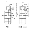
- Figure 2 is a top view of a pair of typical prior art EEPROM memory cells including N+ drain diffusion 201, which is connected via electrical contact 202 to metallization layer 203.
- Cell 200 also includes a first layer of polycrystalline silicon 204 which serves as the floating gate of the EEPROM memory transistor, and a second layer of polycrystalline silicon 205 which serves as the control gate and which forms part of a row line.
- programming, reading, and erasure of cell 200 is all performed from the drain 201 side of the memory cell.
- speed of an EEPROM device is enhanced by utilizing a unique circuit design and operating method which obviates the need for applying a high programming or erase voltage in the path between the memory array and sense amplifier.
- such high programming and erase voltages are applied, as needed, directly to the memory array, thereby allowing all transistors which carry signals from the memory array to the sense amplifier to be fabricated as low voltage devices, thereby increasing their speed of operation and thus the speed of operation of the memory device as a whole.
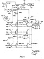
- FIGURE 4 is a schematic diagram of one embodiment of a memory device 400 constructed in accordance with the teachings of this invention.
- Figure 3 is a plan view of a pair of EEPROM memory cells constructed in accordance with the teachings of this invention in which a first layer Pl of polycrystalline silicon forms floating gate 304 located near source 306, rather than near drain 301.
- reading is performed from the drain 301 side of memory cell 300, and programming and erasing performed from the source 306 side of memory cell 300.
- memory device 400 includes row lines 401-1 through 401-N, bit lines 402-1 through 402-M, column select transistors 104-1 through 104-M, and memory array transistors 405-1-1 through 405-N-M.
- Block select transistor 406 is utilized to access the block of memory cells 405-1-1 through 405-N-M.
- memory cell transistors 405-1-1 through 405-N-M are fabricated such that their floating gates are located near their sources, rather than near their drains.
- V DSAT the drain saturation voltage
- V GS the gate-to-source voltage
- V T the threshold voltage
- the read current is limited by the floating gate voltage, which is typically 60 to 70% of the control gate voltage.
- the floating gate voltage typically 60 to 70% of the control gate voltage.
- the read current through the selected memory cell during the read operation is increased since the saturation voltage V DSAT is increased since the drain is influenced by the control gate voltage, rather than the lesser floating gate voltage.
- reading speed is increased. It has been determined that placing the floating gate near the source rather than near the drain increases the read current by about 10 to 15 percent.
- increased speed is also provided due to the fact that column read voltages may be increased, thereby additionally providing increased read current through a selected array transistor, without risking undesirable "soft" writes of the memory cell being read, since the higher read voltage is applied to the drain which is not located near the floating gate.
- undesirable charging may cause a cumulative charge to be placed on the floating gate of a deselected transistor, thereby causing a "soft" write.
- P+ (e.g., Boron) ion implants need not be made to the drains of the memory array transistors as is often the case in prior art structures for enhancing the ability to program the cell, since having a P+N+ junction rather than a P-N+ junction increases the maximum field at the junction leading to greater hot electron generation.
- ion implants can be used on the source side of the memory array transistors where, in accordance with the teachings of this invention, programming occurs by charging the floating gate. By avoiding ion implants on the drains of the memory array transistors, bit line capacitance is reduced, thereby increasing reading speed.
- the P type field implant is not performed near the source of the memory cell transistors, thus increasing the gated diode breakdown voltage of the source junction, which in turn allows greater voltages to be applied to the source in order to improve the performance of the Fowler Nordheim electron tunnelling between the source and the floating gate, as well as decreasing susceptibility of the junction to breakdown.
- Fowler Nordheim tunnelling is independent of temperature and is effective only at high electric fields (typically 7 to 10 Megavolts per centimeter).
- Programming of a selected memory array transistor is performed by applying programming voltage VPP to a selected row line while holding deselected row lines at zero volts, and applying programming voltage VPP through transistor 443 to the sources of all memory array transistors.
- a selected column is grounded by turning on its associated column select transistor, and block select transistor 406 and transistor 421. This causes electrons to be tunneled from the source to the floating gate of the selected transistor.
- programming set transistors 432-1 through 432-M and programming reset transistors 423-1 through 423-M are utilized to minimize the potential for soft programming cells along the selected row line but along deselected columns, which are left floating and thus may be undesirably charged by current flowing from its source to its drain.
- such soft writing is avoided by precharging the deselected bit lines, thereby preventing current from flowing through deselected memory array transistors, which in turn prevents any amount of charging of the floating gates of deselected transistors during the programming of a selected memory array transistor.
- programming a selected memory array cell for example transistor 405-1-1, is performed by first applying a PRGSET signal to lead 432, thus turning on precharge transistors 432-1 through 432-M which apply a predefined voltage (for example, 10 volts) to bit lines 402-1 through 402-M, respectively.
- the PRGSET signal then goes low, turning off transistors 432-1 through 432-M while leaving bit lines 402-1 through 402-M precharged.
- Transistor 421 is then turned on, thereby causing selected bit line 402-1 to be discharged through conducting column select transistor 104-1 and block select transistor 406.
- the deselected columns 402-2 through 402-M remain precharged since their column select transistors 104-2 through 104-M are turned off.
- Source pull down transistor 442 is turned off, and programming voltage VPP is applied through transistor 443 to the sources of all memory array transistors 405-1-1 through 405-N-M.
- Selected memory array transistor 405-1-1 conducts current from its source to its drain, thereby placing a charge on its floating gate.
- bit lines 402-2 through 402-M are discharged by applying a PRG reset signal to lead 422, thus turning on reset transistors 423-1 through 423-M.
- reset transistors 423-1 through 423-M are not used, and the bit lines are discharged by enabling all column select transistors 104-1 through 104-M while transistor 421 is turned on.
- Table 2 reflects, similar to table 1, the programming, reading , and erasure modes of the memory device according to the present invention.
- Row line (control gate) selected VCC (5 volts) deselected: 0 volts bit line (drain) precharged to V ref -V T (typically 1.5 volts) logical 1 stored: pulled low by array transistor, by at least 0.2 volts from precharged level logical 0 stored: not pulled low by array transistor erase line (source) : 0 volts
- Row line (control gate) 0 volts bit line (drain) : 17 volts erase line (source) : Floating
- Row line (control gate) selected VCC (5 volts) deselected : 0 bit line (drain) logical 0 stored: 2 volts logical 1 stored: 1.8 volts erase line (source) : 0
Landscapes
- Read Only Memory (AREA)
- Non-Volatile Memory (AREA)
- Semiconductor Memories (AREA)
Applications Claiming Priority (2)
| Application Number | Priority Date | Filing Date | Title |
|---|---|---|---|
| US275380 | 1988-11-23 | ||
| US07/275,380 US4999812A (en) | 1988-11-23 | 1988-11-23 | Architecture for a flash erase EEPROM memory |
Publications (2)
| Publication Number | Publication Date |
|---|---|
| EP0370416A2 true EP0370416A2 (fr) | 1990-05-30 |
| EP0370416A3 EP0370416A3 (fr) | 1990-12-05 |
Family
ID=23052047
Family Applications (1)
| Application Number | Title | Priority Date | Filing Date |
|---|---|---|---|
| EP19890121391 Withdrawn EP0370416A3 (fr) | 1988-11-23 | 1989-11-18 | Architecture pour mémoire EPROM à effacement éclair |
Country Status (4)
| Country | Link |
|---|---|
| US (1) | US4999812A (fr) |
| EP (1) | EP0370416A3 (fr) |
| JP (1) | JPH03155667A (fr) |
| KR (1) | KR0155357B1 (fr) |
Families Citing this family (27)
| Publication number | Priority date | Publication date | Assignee | Title |
|---|---|---|---|---|
| DE69129492T2 (de) * | 1990-10-02 | 1998-11-05 | Toshiba Kawasaki Shi Kk | Halbleiterspeicher |
| US5241507A (en) * | 1991-05-03 | 1993-08-31 | Hyundai Electronics America | One transistor cell flash memory assay with over-erase protection |
| US5541878A (en) * | 1991-05-09 | 1996-07-30 | Synaptics, Incorporated | Writable analog reference voltage storage device |
| US5166562A (en) * | 1991-05-09 | 1992-11-24 | Synaptics, Incorporated | Writable analog reference voltage storage device |
| JP3375087B2 (ja) * | 1991-10-21 | 2003-02-10 | ローム株式会社 | 半導体記憶装置およびその記憶情報読出方法 |
| US5293328A (en) * | 1992-01-15 | 1994-03-08 | National Semiconductor Corporation | Electrically reprogrammable EPROM cell with merged transistor and optiumum area |
| FR2688333B1 (fr) * | 1992-03-06 | 1994-04-29 | Sgc Thomson Microelectronics S | Dispositif et procede d'effacement par secteurs d'une memoire flash eprom. |
| KR960006748B1 (ko) * | 1993-03-31 | 1996-05-23 | 삼성전자주식회사 | 고속동작 및 저전원공급전압에 적합한 쎌구조를 가지는 불휘발성 반도체 집적회로 |
| DE69305986T2 (de) * | 1993-07-29 | 1997-03-06 | Sgs Thomson Microelectronics | Schaltungsstruktur für Speichermatrix und entsprechende Herstellungsverfahren |
| US5427963A (en) * | 1993-12-10 | 1995-06-27 | Advanced Micro Devices, Inc. | Method of making a MOS device with drain side channel implant |
| US5376573A (en) * | 1993-12-10 | 1994-12-27 | Advanced Micro Devices, Inc. | Method of making a flash EPROM device utilizing a single masking step for etching and implanting source regions within the EPROM core and redundancy areas |
| US5581485A (en) * | 1994-12-08 | 1996-12-03 | Omni Microelectronics, Inc. | Analog vector distance measuring and vector quantization architecture |
| US5920296A (en) * | 1995-02-01 | 1999-07-06 | Pixel International | Flat screen having individually dipole-protected microdots |
| US5801076A (en) * | 1995-02-21 | 1998-09-01 | Advanced Micro Devices, Inc. | Method of making non-volatile memory device having a floating gate with enhanced charge retention |
| KR0172403B1 (ko) * | 1995-11-15 | 1999-03-30 | 김광호 | 불휘발성 반도체 메모리의 데이타 리드회로 |
| US5828603A (en) * | 1997-04-23 | 1998-10-27 | Atmel Corporation | Memory device having a power supply-independent low power consumption bit line voltage clamp |
| JPH10312694A (ja) * | 1997-05-08 | 1998-11-24 | Oki Electric Ind Co Ltd | 半導体不揮発性メモリおよびそのための電源回路 |
| US6175520B1 (en) | 1997-05-30 | 2001-01-16 | Alliance Semiconductor Corporation | Nonvolatile memory array having local program load line repeaters |
| US6181607B1 (en) | 1999-04-22 | 2001-01-30 | Aplus Flash Technology, Inc. | Reversed split-gate cell array |
| US6031765A (en) * | 1999-04-22 | 2000-02-29 | Aplus Flash Technology, Inc. | Reversed split-gate cell array |
| US6977841B2 (en) * | 2002-11-21 | 2005-12-20 | Micron Technology, Inc. | Preconditioning of defective and redundant columns in a memory device |
| US8324667B2 (en) | 2004-01-05 | 2012-12-04 | International Business Machines Corporation | Amplifiers using gated diodes |
| US7116594B2 (en) * | 2004-09-03 | 2006-10-03 | International Business Machines Corporation | Sense amplifier circuits and high speed latch circuits using gated diodes |
| WO2006038249A1 (fr) * | 2004-09-30 | 2006-04-13 | Spansion Llc | Dispositif semiconducteur et procede de commande associe |
| US20090307140A1 (en) | 2008-06-06 | 2009-12-10 | Upendra Mardikar | Mobile device over-the-air (ota) registration and point-of-sale (pos) payment |
| US7995384B2 (en) | 2008-08-15 | 2011-08-09 | Macronix International Co., Ltd. | Electrically isolated gated diode nonvolatile memory |
| US8862767B2 (en) | 2011-09-02 | 2014-10-14 | Ebay Inc. | Secure elements broker (SEB) for application communication channel selector optimization |
Family Cites Families (3)
| Publication number | Priority date | Publication date | Assignee | Title |
|---|---|---|---|---|
| JPS6046554B2 (ja) * | 1978-12-14 | 1985-10-16 | 株式会社東芝 | 半導体記憶素子及び記憶回路 |
| US4698787A (en) * | 1984-11-21 | 1987-10-06 | Exel Microelectronics, Inc. | Single transistor electrically programmable memory device and method |
| US4852062A (en) * | 1987-09-28 | 1989-07-25 | Motorola, Inc. | EPROM device using asymmetrical transistor characteristics |
-
1988
- 1988-11-23 US US07/275,380 patent/US4999812A/en not_active Expired - Fee Related
-
1989
- 1989-11-18 EP EP19890121391 patent/EP0370416A3/fr not_active Withdrawn
- 1989-11-22 KR KR1019890016950A patent/KR0155357B1/ko not_active Expired - Fee Related
- 1989-11-24 JP JP1303482A patent/JPH03155667A/ja active Pending
Also Published As
| Publication number | Publication date |
|---|---|
| EP0370416A3 (fr) | 1990-12-05 |
| KR900008528A (ko) | 1990-06-04 |
| KR0155357B1 (ko) | 1998-12-01 |
| JPH03155667A (ja) | 1991-07-03 |
| US4999812A (en) | 1991-03-12 |
Similar Documents
| Publication | Publication Date | Title |
|---|---|---|
| US4999812A (en) | Architecture for a flash erase EEPROM memory | |
| US5511022A (en) | Depletion mode NAND string electrically erasable programmable semiconductor memory device and method for erasing and programming thereof | |
| US5596525A (en) | Memory cell of nonvolatile semiconductor memory device | |
| EP0297540B1 (fr) | Cellule de mémoire d'un dispositif de mémoire semi-conductrice non volatile | |
| US5270969A (en) | Electrically programmable nonvolatile semiconductor memory device with nand cell structure | |
| US5666307A (en) | PMOS flash memory cell capable of multi-level threshold voltage storage | |
| US5812452A (en) | Electrically byte-selectable and byte-alterable memory arrays | |
| US4366555A (en) | Electrically erasable programmable read only memory | |
| EP0055594B1 (fr) | Dispositif de mémoire non-volatile à semi-conducteur programmable électriquement | |
| EP0025155B1 (fr) | Dispositif de mémoire non-volatile à semi-conducteurs | |
| EP0656627A2 (fr) | Circuit à tension de seuil ajustable | |
| JPH05159589A (ja) | 過消去保護を有する単トランジスタセルフラッシュメモリアレイ | |
| US20080266976A1 (en) | Nand memory device and programming methods | |
| EP0387889B1 (fr) | Mémoire rémanente en semi-conducteur | |
| KR19990014206A (ko) | 불휘발성 반도체 기억장치 | |
| US6420753B1 (en) | Electrically selectable and alterable memory cells | |
| KR19990013057A (ko) | 단일 비트 데이터와 다중 비트 데이터를 동일한 칩에 선택적으로 저장하는 플래시 메모리 장치의 독출 및 기입 방법 | |
| US5943268A (en) | Non-volatile latch having PMOS floating gate memory cells | |
| KR0165468B1 (ko) | 반도체 메모리소자 및 그 제조방법 및 그 구동방법 | |
| US5808940A (en) | Nonvolatile semiconductor memory | |
| US5280187A (en) | Electrically programmable and erasable semiconductor memory and method of operating same | |
| US6034899A (en) | Memory cell of nonvolatile semiconductor memory device | |
| US6147907A (en) | Biasing scheme to reduce stress on non-selected cells during read | |
| US5877981A (en) | Nonvolatile semiconductor memory device having a matrix of memory cells | |
| US5227652A (en) | Electrically programmable and erasable semiconductor memory and method of operating same |
Legal Events
| Date | Code | Title | Description |
|---|---|---|---|
| PUAI | Public reference made under article 153(3) epc to a published international application that has entered the european phase |
Free format text: ORIGINAL CODE: 0009012 |
|
| AK | Designated contracting states |
Kind code of ref document: A2 Designated state(s): DE FR GB IT NL |
|
| PUAL | Search report despatched |
Free format text: ORIGINAL CODE: 0009013 |
|
| AK | Designated contracting states |
Kind code of ref document: A3 Designated state(s): DE FR GB IT NL |
|
| 17P | Request for examination filed |
Effective date: 19910508 |
|
| 17Q | First examination report despatched |
Effective date: 19930308 |
|
| STAA | Information on the status of an ep patent application or granted ep patent |
Free format text: STATUS: THE APPLICATION IS DEEMED TO BE WITHDRAWN |
|
| 18D | Application deemed to be withdrawn |
Effective date: 19960501 |