EP0370934B1 - Procédé et ensemble d'alimentation en métal fondu de la lingotière d'une installation de coulée continue d'ébauches minces - Google Patents
Procédé et ensemble d'alimentation en métal fondu de la lingotière d'une installation de coulée continue d'ébauches minces Download PDFInfo
- Publication number
- EP0370934B1 EP0370934B1 EP89470024A EP89470024A EP0370934B1 EP 0370934 B1 EP0370934 B1 EP 0370934B1 EP 89470024 A EP89470024 A EP 89470024A EP 89470024 A EP89470024 A EP 89470024A EP 0370934 B1 EP0370934 B1 EP 0370934B1
- Authority
- EP
- European Patent Office
- Prior art keywords
- nozzle
- ingot mould
- molten metal
- distributor
- tube
- Prior art date
- Legal status (The legal status is an assumption and is not a legal conclusion. Google has not performed a legal analysis and makes no representation as to the accuracy of the status listed.)
- Expired - Lifetime
Links
Images


Classifications
-
- B—PERFORMING OPERATIONS; TRANSPORTING
- B22—CASTING; POWDER METALLURGY
- B22D—CASTING OF METALS; CASTING OF OTHER SUBSTANCES BY THE SAME PROCESSES OR DEVICES
- B22D11/00—Continuous casting of metals, i.e. casting in indefinite lengths
- B22D11/10—Supplying or treating molten metal
-
- B—PERFORMING OPERATIONS; TRANSPORTING
- B22—CASTING; POWDER METALLURGY
- B22D—CASTING OF METALS; CASTING OF OTHER SUBSTANCES BY THE SAME PROCESSES OR DEVICES
- B22D11/00—Continuous casting of metals, i.e. casting in indefinite lengths
- B22D11/10—Supplying or treating molten metal
- B22D11/106—Shielding the molten jet
-
- B—PERFORMING OPERATIONS; TRANSPORTING
- B22—CASTING; POWDER METALLURGY
- B22D—CASTING OF METALS; CASTING OF OTHER SUBSTANCES BY THE SAME PROCESSES OR DEVICES
- B22D41/00—Casting melt-holding vessels, e.g. ladles, tundishes, cups or the like
- B22D41/50—Pouring-nozzles
Definitions
- the present invention is in the field of metal production, and relates more particularly to the continuous casting techniques of molten metals, in particular steel for the preparation of thin blanks.
- the present invention relates to a method for supplying molten metal to the ingot mold of a continuous casting installation for thin blanks, according to which the ingot mold is fed with molten metal by at least one vertical pouring stream flowing of the orifice of a nozzle connected to a distributor of molten metal by a pouring tube, and the level of molten metal in the ingot mold is regulated by acting on the flow of metal entering the pouring tube.
- the molten metal is supplied to the ingot mold generally by one or more calibrated nozzles connected to a molten metal distributor which during the casting of the latter occupies a fixed position above the ingot mold.
- the top of the mold is flared so that it can receive the pouring nozzle.
- the level of the free surface of the metal in the ingot mold is detected by an appropriate device which controls a flow control device, and therefore, for a determined product extraction speed, of the level of metal in the ingot mold, the outlet of said device acting on means for adjusting the inlet section of the nozzle to modify said inlet section and consequently the pressure drop, and thus the flow rate of the nozzle.
- the mouth of the nozzles is in a fixed position inside the ingot mold, and can either be immersed in the molten metal, or emerge above the free surface of the molten metal contained in the ingot mold so as to provide a vertical pouring jet.
- the fixed station mounting of the nozzles is known for example from British patents No. 1,083,262 and 1,157,818 and French patent No. 1,509,266.
- the life of the nozzle is then limited by the erosion it undergoes at the meniscus.
- the thickness of the casting chamber of the mold being very small compared to its transverse dimension, that is to say its width, the walls of the mold are very close to the nozzle (s), and the risk of formation of the solidification bridges is all the greater.
- the orifices of the nozzle preferential currents of circulation of the liquid metal are created and for certain arrangements, there is a risk of forming a concentration of inclusions in certain areas and in particular under the tube. of casting.
- the object of the present invention is to overcome such drawbacks and to improve the metallurgical quality of the thin blanks obtained by continuous casting.
- the object is achieved according to the invention, by the fact that in the above-mentioned method, the lower end of the nozzle is maintained at a constant predetermined distance above the free surface of the molten metal contained in the mold. by vertical displacement of the distributor as a function of variations in the level of the molten metal contained in the ingot mold relative to a fixed reference level, while maintaining said lower end of the nozzle inside the ingot mold, and the jet is subjected to casting a horizontal sweeping movement, parallel to the large walls of the mold, by a corresponding displacement of the nozzle, and the tube and the distributor which are integral with it.
- the free height of the jet leaving the nozzle remains constant and as low as possible regardless of the level of the molten metal in the ingot mold, so that the stirring effect caused by the jet of molten metal in the metal of the blank being solidified is always homogeneous.
- the liquid metal entering the distributor must be of good quality and should not be altered.
- the pouring tube, the nozzle and the pouring jet are surrounded by a layer of liquefied gas, non-oxidizing with respect to the cast metal, which flows along said pouring tube and along said nozzle, and the free surface of the molten metal contained therein is covered over a height at least equal to the distance separating the lower end of said nozzle and said free metal surface.
- An annular chamber communicating with a source of liquefied gas and opening out above the free surface of the molten metal and contained can be formed around the pouring tube and the nozzle, using an appropriate sleeve fixed to the distributor. in the ingot mold through an annular orifice, and said liquefied gas is circulated in said annular chamber, said liquefied gas flowing through said annular orifice above said free metal surface.
- the liquefied neutral gas thus protects the casting jet and the metal of the ingot mold against any oxidation by oxygen in the air.
- the sealing of the pouring tube is completed by the sleeve and the liquefied gas contained in the annular space.
- the thermal insulation formed by the gas and the sleeve contributes to keeping the pouring tube at a temperature as high as possible, which counteracts the deposition of oxides, such as alumina, which, in known devices, causes plugging the tube.
- a substance having a high reflecting power vis-à-vis the radiation emitted by the metal can be incorporated into the liquefied gas.
- the tube and the nozzle are then thermally insulated so as not to modify the temperature of the liquid metal which passes through them.
- the liquefied gas in the annular chamber can advantageously be maintained at a pressure close to the average ferrostatic pressure existing in the pouring tube, at least partially eliminating the radial stresses in the tube due to the ferrostatic pressure, and thereby improving the lifetime of tube and nozzle.
- the present invention also relates to a supply assembly for a narrow ingot mold of the type comprising a molten metal distributor placed above the ingot mold and provided with a pouring tube, at the lower end of which is attached a nozzle, and a stopper arranged above the orifice of the pouring tube and intended to regulate the flow of metal in the pouring tube, and comprising a device for measuring and regulating the level of the molten metal in the ingot mold, coupled with said stopper rod, the lower end of said nozzle penetrating inside the mold and being maintained at the level of the free surface of the molten metal contained in the mold, assembly provided in particular for carrying out the method of the invention , characterized in that it comprises means making it possible to move the dispenser vertically as a function of the level of metal in the ingot mold and means to move the lateral Lement the distributor in a horizontal sweeping movement parallel to the large walls of the mold.
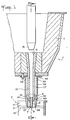
- the feed installation 1 has been designated by the feed installation of a narrow ingot mold 2 intended for the production of thin blanks 3.
- the feed installation 1 comprises a distributor 4 or distributor containing a bath of molten steel and having an orifice 5 formed through the bottom.
- the distributor 4 continuously feeds, by a vertical pouring jet 6, the mold 2 at the base of which is also withdrawn continuously, the thin blank 3 partially solidified.
- the mold 2 can be subjected to vertical oscillations.
- the vertical pouring jet 6 comes from the orifice 7 of a nozzle 8 fixed to the lower end 9 of a pouring tube 10 opening to the orifice 5 through the bottom of the distributor 4.
- the upper part 11 of the mold 2 is flared so that the lower end 12 of the nozzle 8 is located in the mold 2 and above the free surface 13 of the molten metal in the mold.
- An apparatus 14 for measuring the height of the free surface 13 of the metal in the mold provides indications to a level control device in the mold 15 which acts on the stopper 16 using a jack 17.
- the stopper 16 closes more or less the orifice 5, thus creating a pressure drop which modifies the ferrostatic pressure in the nozzle 8 and thereby the flow rate of the casting jet 6.
- the steel flow rate is determined by the section of the nozzle and the ferrostatic height, that is to say the height of liquid metal above said nozzle.
- the stopper rod or any other suitable shutter, is used mainly for starting and stopping the casting.
- the stopper rod also makes it possible to modulate the flow rate of the nozzle, in a proportion however small, by creating a pressure drop which is added, compared to the ferrostatic pressure, to the pressure drop created by the nozzle.
- the distributor 4 is carried by a set of cylinders 18 and the height of the distributor 4 is regulated by a height regulation device 19 acting on the cylinders 18 and continuously coupled to the level regulation device in the mold 15 so that the height of the pouring jet 6, in other words the distance separating the orifice 7 of the nozzle 8 from the free surface 13 of the metal in the ingot mold, is constant whatever the level of the molten metal in the ingot mold 2.
- the number of casting jets 6 is a function of the largest dimension of the ingot mold 2. For example, a blank of 1600 mm by 50 mm requires three casting jets poured out by nozzles 8 aligned and regularly spaced between the walls of larger dimension 20 and 21 of the mold 2.
- the distributor 4 is mounted movable horizontally in a back-and-forth movement in a direction parallel to the large walls 20 and 21 of the ingot mold 2.
- the jacks 18 carrying the distributor 4 are fixed on a support 22 which is moved under the action of a control member not shown, in a back-and-forth movement in the direction of the largest dimension of the mold 2, so that the nozzles 8 located near the lateral ends of the ingot mold 2 alternately approach and move away from the corresponding ends of the ingot mold 2.
- the duration of a lateral movement of the distributor 4 is approximately equal to a quarter of the time taken by the blank 3 to pass through the ingot mold 2.
- the displacement stroke of the distributor 4 is 510 mm, and the displacement is achieved in 5.36 s, which gives a translation speed of 5.7 m / min, which, from the mechanical point of view, is very slow.
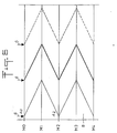
- FIG. 6 gives an example of the scanning of the point of impact A of a pouring jet 6 represented by an arrow through the blank 3 as a function of the progress of the blank which is proportional to time.
- the meniscus M0 defines a slice of the blank 3 which progresses in the mold 3 and which is in position M2 in the middle of the height of the mold when the pouring jet 6 has made a complete lateral displacement, back and forth, in the ingot mold.
- point A2 ie 50 cm from point A0, the solidification of the skin has increased in thickness by 9 mm and there remains a liquid core of the order of 32 mm between the two large faces of the blank 3.
- Lateral displacement pouring jets 6 modify the streams of molten metal according to the lateral position of the pouring jets 6, thus causing stirring of the liquid core of the blank 3 and avoiding the skin solidification irregularities.
- the pouring tube 10 is made in one piece from a refractory material and the inner conduit of the tube, flared in the upper part has no discontinuity between its two ends and the inner conduit of the nozzle 8 is also flared its upper part , so that, in operation, the pouring tube 10 and the nozzle 8 are filled with liquid metal under ferrostatic pressure.
- the nozzle flow 8 is a function of the section of the orifice 7 and of the ferrostatic pressure. As an indication with a nozzle having a diameter of 19 mm and a length of 140 mm fixed to a pouring tube having a diameter of 50 mm and a length of 650 mm, the steel flow rate is 600 kg per minute.
- the air does not enter the nozzle, because the air has three harmful effects, one on the metallic quality of the blank, the other on the production of oxides in the nozzle which tend to reduce the section of the orifice 7, and finally, to a certain extent, it cools the tube.
- the pouring tube 10 is surrounded by a sleeve 25 of generally cylindrical shape which is tightly fixed on the underside 26 of the distributor tank 4.
- the internal diameter of the sleeve 25 is greater than the external diameter of the pouring tube 10, so as to provide an annular chamber 27 between the sleeve 25 and the pouring tube 10.
- the sleeve 25 has in its upper part 28, an orifice 29 communicating with a source of liquefied neutral gas not shown in the drawing.
- the lower end 9 of the tube 10 has a tapered or sectional shape and the lower end 30 of the sleeve 25 has an internal wall 31 having a conical shape adapted to the external wall of the lower end 9 of the pouring tube, such so that the annular chamber 27 opens out near the lower point of the tube 10 through an annular opening 32 situated around the nozzle 8.
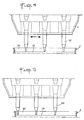
- two extensions 33 are formed which are diametrically opposite with respect to the nozzle 8.
- the extensions 33 extend vertically at a small distance from the nozzle 8 and are located between the large walls 20 and 21 of the mold 2, and their lower points 34 are approximately at the same level as the level of the orifice 7 of the nozzle 8.
- annular opening 32 of the annular chamber 27 opens out above the free surface of the metal in the mold 13, and above the wall portions 35 of the mold located in the vicinity of the nozzle 8.
- a neutral liquefied gas for example liquid nitrogen at -196 ° C, preferably under pressure so as to balance the ferrostatic pressure inside the pouring tube 10.
- the liquefied gas fills the chamber 27 and flows through the annular opening 32 either on the wall portions 35 of the mold, or directly along the two extensions 33 of the sleeve 25 to finally cover the free surface 13 of the metal in the mold over a thickness such that the casting jet 6 is completely immersed in the layer of liquefied gas.
- the molten metal of the ingot mold and the casting jet 6 are thus fully protected from the oxygen in the air.
- the nozzle 8 and the lower part of the pouring tube 10 are completely surrounded by a layer of liquefied gas ensuring the thermal protection of the metal contained in the tube - 10 and in the nozzle 8 and ensuring a complementary sealing of the assembly. .
- the invention is applicable to all types of installations for the continuous casting of thin blanks comprising a narrow ingot mold, whether the walls thereof are fixed, or whether they are subjected to vertical oscillations, or else that they accompany the product during its extraction.
- This latter category includes in particular the installations known as "casting between cylinders", in which the ingot mold is delimited by the cooled external surfaces of two parallel cylinders rotating in opposite directions, and by end plates closing off the space laterally. of casting.
- a change in the casting speed can result in a significant increase or decrease in the level of the metal in the ingot mold: it is therefore particularly advantageous to keep the distance between the feed nozzle and the surface of the metal by means of the installation which has just been described.
Landscapes
- Engineering & Computer Science (AREA)
- Mechanical Engineering (AREA)
- Continuous Casting (AREA)
- Feeding, Discharge, Calcimining, Fusing, And Gas-Generation Devices (AREA)
- Confectionery (AREA)
- Nonmetallic Welding Materials (AREA)
Priority Applications (1)
| Application Number | Priority Date | Filing Date | Title |
|---|---|---|---|
| AT89470024T ATE74037T1 (de) | 1988-11-23 | 1989-11-22 | Verfahren und einrichtung zum versorgen einer kokille mit geschmolzenem metall in einer stranggiesseinrichtung fuer duenne vorbloecke. |
Applications Claiming Priority (2)
| Application Number | Priority Date | Filing Date | Title |
|---|---|---|---|
| FR8815285A FR2639267B1 (fr) | 1988-11-23 | 1988-11-23 | Procede et ensemble d'alimentation en metal fondu de la lingotiere d'une installation de coulee continue d'ebauches minces |
| FR8815285 | 1988-11-23 |
Publications (2)
| Publication Number | Publication Date |
|---|---|
| EP0370934A1 EP0370934A1 (fr) | 1990-05-30 |
| EP0370934B1 true EP0370934B1 (fr) | 1992-03-25 |
Family
ID=9372164
Family Applications (1)
| Application Number | Title | Priority Date | Filing Date |
|---|---|---|---|
| EP89470024A Expired - Lifetime EP0370934B1 (fr) | 1988-11-23 | 1989-11-22 | Procédé et ensemble d'alimentation en métal fondu de la lingotière d'une installation de coulée continue d'ébauches minces |
Country Status (9)
| Country | Link |
|---|---|
| US (1) | US5174360A (cs) |
| EP (1) | EP0370934B1 (cs) |
| JP (1) | JPH02182362A (cs) |
| AT (1) | ATE74037T1 (cs) |
| BR (1) | BR8905900A (cs) |
| CA (1) | CA2003609A1 (cs) |
| CS (1) | CS651489A3 (cs) |
| DE (1) | DE68901082D1 (cs) |
| FR (1) | FR2639267B1 (cs) |
Families Citing this family (5)
| Publication number | Priority date | Publication date | Assignee | Title |
|---|---|---|---|---|
| FR2677284B1 (fr) * | 1991-06-07 | 1993-08-27 | Pechiney Aluminium | Procede et appareillage pour la coulee automatique de demi-produits. |
| EP0598972A1 (en) * | 1992-11-27 | 1994-06-01 | REYNOLDS WHEELS S.p.A. | A bush for directing a stream of molten metal into a mould |
| DE4322316C1 (de) * | 1993-07-05 | 1995-03-16 | Vaw Ver Aluminium Werke Ag | Einlaufsystem für eine Aluminiumstranggußanlage |
| US20110049197A1 (en) * | 2009-08-06 | 2011-03-03 | Paul Anthony Withey | Liquid device having filter |
| CN113290211A (zh) * | 2021-05-27 | 2021-08-24 | 青海盐湖镁业有限公司 | 一种环保型纯镁及镁合金铸造输送机 |
Family Cites Families (14)
| Publication number | Priority date | Publication date | Assignee | Title |
|---|---|---|---|---|
| GB1083262A (en) * | 1964-11-24 | 1967-09-13 | United Steel Companies Ltd | Methods of and apparatus for use in the continuous casting of steel |
| GB1157818A (en) * | 1965-09-23 | 1969-07-09 | United States Steel Corp | Nozzle Extension for Continuous Casting |
| BE692176A (cs) * | 1966-03-15 | 1967-06-16 | ||
| US3521698A (en) * | 1967-02-06 | 1970-07-28 | Piero Colombo | Apparatus for the continuous casting of flat blooms |
| US3502134A (en) * | 1967-07-19 | 1970-03-24 | United States Steel Corp | Continuous casting method with inert gas puffs to prevent skulling |
| US3578062A (en) * | 1968-03-05 | 1971-05-11 | Nippon Kokan Kk | Method of and apparatus for continuous casting with immersion-type long nozzles |
| US3628706A (en) * | 1968-10-15 | 1971-12-21 | Southwire Co | Long life spout |
| JPS6015423B2 (ja) * | 1977-12-27 | 1985-04-19 | 松下電器産業株式会社 | 溶融材料供給装置 |
| JPS5864308A (ja) * | 1981-10-12 | 1983-04-16 | Takaoka Kogyo Kk | バ−ミキユラ−黒鉛鋳鉄の製造方法 |
| GB2111879B (en) * | 1981-12-04 | 1985-06-19 | Air Prod & Chem | Apparatus for shielding molten metal during teeming |
| DE3339586A1 (de) * | 1983-11-02 | 1985-05-23 | Didier-Werke Ag, 6200 Wiesbaden | Eintauchausguss |
| IT1176428B (it) * | 1984-07-18 | 1987-08-18 | Radex Italiana Spa | Manicotto di uscita in un dispositivo per controllare l'efflusso di acciaio fuso da una siviera o da una paniera |
| US4730660A (en) * | 1984-09-05 | 1988-03-15 | Metacon Aktiengesellschaft | Process for casting molten metal into several strands |
| DE3509932A1 (de) * | 1985-03-19 | 1986-10-02 | Metacon AG, Zürich | Verfahren zum anfahren einer stranggiessanlage |
-
1988
- 1988-11-23 FR FR8815285A patent/FR2639267B1/fr not_active Expired - Lifetime
-
1989
- 1989-11-17 CS CS896514A patent/CS651489A3/cs unknown
- 1989-11-22 EP EP89470024A patent/EP0370934B1/fr not_active Expired - Lifetime
- 1989-11-22 CA CA002003609A patent/CA2003609A1/fr not_active Abandoned
- 1989-11-22 DE DE8989470024T patent/DE68901082D1/de not_active Expired - Lifetime
- 1989-11-22 AT AT89470024T patent/ATE74037T1/de not_active IP Right Cessation
- 1989-11-22 US US07/440,555 patent/US5174360A/en not_active Expired - Fee Related
- 1989-11-23 BR BR898905900A patent/BR8905900A/pt unknown
- 1989-11-24 JP JP1306330A patent/JPH02182362A/ja active Pending
Also Published As
| Publication number | Publication date |
|---|---|
| EP0370934A1 (fr) | 1990-05-30 |
| FR2639267B1 (fr) | 1991-02-22 |
| CS651489A3 (en) | 1992-11-18 |
| ATE74037T1 (de) | 1992-04-15 |
| JPH02182362A (ja) | 1990-07-17 |
| FR2639267A1 (fr) | 1990-05-25 |
| DE68901082D1 (de) | 1992-04-30 |
| US5174360A (en) | 1992-12-29 |
| BR8905900A (pt) | 1990-06-12 |
| CA2003609A1 (fr) | 1990-05-23 |
Similar Documents
| Publication | Publication Date | Title |
|---|---|---|
| EP2099576B1 (fr) | Busette a jet creux pour coulee continue d'acier | |
| EP0057651A2 (fr) | Procédé de solidification et de refroidissement rapides par coulée continue de produits fondus à base d'oxydes métalliques | |
| CH632685A5 (fr) | Procede pour le moulage en coquille avec refroidissement direct de metaux non ferreux, appareil pour sa mise en oeuvre et application de ce procede. | |
| FR2523005A1 (fr) | Procede et installation de coulee d'un metal non ferreux en lingotiere | |
| EP0370934A1 (fr) | Procédé et ensemble d'alimentation en métal fondu de la lingotière d'une installation de coulée continue d'ébauches minces | |
| EP0743114B2 (fr) | Procédé de lubrification des parois d'une lingotière de coulée continue des métaux et lingotière pour sa mise en oeuvre | |
| EP0089282B1 (fr) | Procédé et installation de protection d'un jet de coulée de métal liquide | |
| FR2634678A1 (fr) | Couverture de protection pour la surface d'un acier en fusion, utilisee dans un appareil de coulee continue | |
| EP0242347A2 (fr) | Dispositif pour la coulée d'un métal en phase pâteuse | |
| FR2607738A3 (fr) | Dispositif pour l'alimentation en metal en fusion des lingotieres de coulee continue | |
| FR2747062A1 (fr) | Lingotiere de coulee continue pour la coulee continue en charge verticale des metaux | |
| FR2673552A1 (fr) | Repartiteur de coulee continue d'acier. | |
| EP0527717B1 (fr) | Procédé et dispositif pour la coulée continue d'un métal en fusion | |
| BE1015358A3 (fr) | Procede et dispositif pour la coulee continue en charge d'un metal en fusion. | |
| FR2704786A3 (fr) | Procédé de coulée continue en charge des métaux, notamment de l'acier, et lingotière pour sa mise en Óoeuvre. | |
| BE1004046A3 (fr) | Dispositif de dosage et de transport d'une masse pulverulente. | |
| EP0943380A1 (fr) | Installation de coulée en continu d'un produit métallique et procédés de mise en oeuvre d'une telle installation | |
| FR2618704A3 (fr) | Procede et dispositif d'alimentation d'une lingotiere de coulee continue de produits minces | |
| EP0206869B1 (fr) | Installation de coulée continue de métal en bande mince | |
| FR2619032A3 (fr) | Procede et dispositif d'alimentation en metal liquide d'une installation de coulee continue de produits minces en lingotiere a parois mobiles | |
| EP0452294B1 (fr) | Procédé et installation pour la coulée continue d'un métal | |
| WO1997037794A1 (fr) | Procede de coulee continue des metaux et lingotiere pour sa mise en oeuvre | |
| EP1056559A1 (fr) | Lingotiere pluriangulaire de coulee continue en charge d'un produit metallurgique | |
| FR2526340A1 (fr) | Procede et installation de coulee continue | |
| LU86395A1 (fr) | Dispositif et procede pour la coulee continue de l'acier |
Legal Events
| Date | Code | Title | Description |
|---|---|---|---|
| PUAI | Public reference made under article 153(3) epc to a published international application that has entered the european phase |
Free format text: ORIGINAL CODE: 0009012 |
|
| AK | Designated contracting states |
Kind code of ref document: A1 Designated state(s): AT BE CH DE ES FR GB GR IT LI LU NL SE |
|
| 17P | Request for examination filed |
Effective date: 19900924 |
|
| 17Q | First examination report despatched |
Effective date: 19910604 |
|
| GRAA | (expected) grant |
Free format text: ORIGINAL CODE: 0009210 |
|
| AK | Designated contracting states |
Kind code of ref document: B1 Designated state(s): AT BE CH DE ES FR GB GR IT LI LU NL SE |
|
| PG25 | Lapsed in a contracting state [announced via postgrant information from national office to epo] |
Ref country code: IT Free format text: LAPSE BECAUSE OF FAILURE TO SUBMIT A TRANSLATION OF THE DESCRIPTION OR TO PAY THE FEE WITHIN THE PRE;WARNING: LAPSES OF ITALIAN PATENTS WITH EFFECTIVE DATE BEFORE 2007 MAY HAVE OCCURRED AT ANY TIME BEFORE 2007. THE CORRECT EFFECTIVE DATE MAY BE DIFFERENT FROM THE ONE RECORDED.SCRIBED TIME-LIMIT Effective date: 19920325 Ref country code: ES Free format text: THE PATENT HAS BEEN ANNULLED BY A DECISION OF A NATIONAL AUTHORITY Effective date: 19920325 Ref country code: SE Effective date: 19920325 Ref country code: NL Effective date: 19920325 Ref country code: GR Free format text: LAPSE BECAUSE OF FAILURE TO SUBMIT A TRANSLATION OF THE DESCRIPTION OR TO PAY THE FEE WITHIN THE PRESCRIBED TIME-LIMIT Effective date: 19920325 Ref country code: GB Effective date: 19920325 Ref country code: AT Effective date: 19920325 |
|
| REF | Corresponds to: |
Ref document number: 74037 Country of ref document: AT Date of ref document: 19920415 Kind code of ref document: T |
|
| REF | Corresponds to: |
Ref document number: 68901082 Country of ref document: DE Date of ref document: 19920430 |
|
| NLV1 | Nl: lapsed or annulled due to failure to fulfill the requirements of art. 29p and 29m of the patents act | ||
| GBV | Gb: ep patent (uk) treated as always having been void in accordance with gb section 77(7)/1977 [no translation filed] | ||
| PG25 | Lapsed in a contracting state [announced via postgrant information from national office to epo] |
Ref country code: LI Effective date: 19921130 Ref country code: LU Free format text: LAPSE BECAUSE OF NON-PAYMENT OF DUE FEES Effective date: 19921130 Ref country code: BE Effective date: 19921130 Ref country code: CH Effective date: 19921130 |
|
| PLBE | No opposition filed within time limit |
Free format text: ORIGINAL CODE: 0009261 |
|
| STAA | Information on the status of an ep patent application or granted ep patent |
Free format text: STATUS: NO OPPOSITION FILED WITHIN TIME LIMIT |
|
| 26N | No opposition filed | ||
| BERE | Be: lapsed |
Owner name: INSTITUT DE RECHERCHES DE LA SIDERURGIE FRANCAISE Effective date: 19921130 |
|
| PG25 | Lapsed in a contracting state [announced via postgrant information from national office to epo] |
Ref country code: FR Effective date: 19930730 |
|
| REG | Reference to a national code |
Ref country code: CH Ref legal event code: PL |
|
| PG25 | Lapsed in a contracting state [announced via postgrant information from national office to epo] |
Ref country code: DE Effective date: 19930803 |
|
| REG | Reference to a national code |
Ref country code: FR Ref legal event code: ST |