EP0371358B1 - Compensation du temps de retard dans un émetteur-récepteur radio - Google Patents
Compensation du temps de retard dans un émetteur-récepteur radio Download PDFInfo
- Publication number
- EP0371358B1 EP0371358B1 EP89121330A EP89121330A EP0371358B1 EP 0371358 B1 EP0371358 B1 EP 0371358B1 EP 89121330 A EP89121330 A EP 89121330A EP 89121330 A EP89121330 A EP 89121330A EP 0371358 B1 EP0371358 B1 EP 0371358B1
- Authority
- EP
- European Patent Office
- Prior art keywords
- timing
- delay
- transmissions
- predetermined
- signal
- Prior art date
- Legal status (The legal status is an assumption and is not a legal conclusion. Google has not performed a legal analysis and makes no representation as to the accuracy of the status listed.)
- Expired - Lifetime
Links
- 230000005540 biological transmission Effects 0.000 claims abstract description 17
- 230000001934 delay Effects 0.000 claims abstract description 4
- 238000004891 communication Methods 0.000 claims description 2
- 238000005259 measurement Methods 0.000 claims description 2
- 230000001419 dependent effect Effects 0.000 claims 2
- 230000007274 generation of a signal involved in cell-cell signaling Effects 0.000 claims 1
- 230000000977 initiatory effect Effects 0.000 claims 1
- 230000001413 cellular effect Effects 0.000 abstract description 4
- 230000011664 signaling Effects 0.000 description 3
- 238000004364 calculation method Methods 0.000 description 2
- 230000001360 synchronised effect Effects 0.000 description 2
- 230000032683 aging Effects 0.000 description 1
- 238000010219 correlation analysis Methods 0.000 description 1
- 230000003111 delayed effect Effects 0.000 description 1
- 238000010586 diagram Methods 0.000 description 1
- 230000000694 effects Effects 0.000 description 1
- 238000000034 method Methods 0.000 description 1
- 238000012986 modification Methods 0.000 description 1
- 230000004048 modification Effects 0.000 description 1
Images
Classifications
-
- H—ELECTRICITY
- H04—ELECTRIC COMMUNICATION TECHNIQUE
- H04W—WIRELESS COMMUNICATION NETWORKS
- H04W56/00—Synchronisation arrangements
- H04W56/004—Synchronisation arrangements compensating for timing error of reception due to propagation delay
- H04W56/0045—Synchronisation arrangements compensating for timing error of reception due to propagation delay compensating for timing error by altering transmission time
-
- H—ELECTRICITY
- H04—ELECTRIC COMMUNICATION TECHNIQUE
- H04B—TRANSMISSION
- H04B7/00—Radio transmission systems, i.e. using radiation field
- H04B7/24—Radio transmission systems, i.e. using radiation field for communication between two or more posts
- H04B7/26—Radio transmission systems, i.e. using radiation field for communication between two or more posts at least one of which is mobile
- H04B7/2662—Arrangements for Wireless System Synchronisation
- H04B7/2671—Arrangements for Wireless Time-Division Multiple Access [TDMA] System Synchronisation
- H04B7/2678—Time synchronisation
- H04B7/2681—Synchronisation of a mobile station with one base station
-
- H—ELECTRICITY
- H04—ELECTRIC COMMUNICATION TECHNIQUE
- H04M—TELEPHONIC COMMUNICATION
- H04M1/00—Substation equipment, e.g. for use by subscribers
- H04M1/72—Mobile telephones; Cordless telephones, i.e. devices for establishing wireless links to base stations without route selection
- H04M1/724—User interfaces specially adapted for cordless or mobile telephones
Definitions
- This invention relates to a radio transceiver, such as a mobile cellular radio telephone for use on the OEBL-C system.
- a radio comprises a receiver section, a transmitter section, a control unit for controlling timing of transmissions, and means for generating a predetermined signal and feeding it through the transmitter section.
- a mobile radio's logic unit measures the time of arrival of a predefined bit sequence issued from a base station.
- the predefined bit sequence is generally 34 bits, made up of a Barker code repeated three times, followed by a "1"; hereinafter referred to as the "preamble".
- the control unit controls the timing of transmissions and signalling sequences, so that an exact 150 millisecond delay between received and transmitted data is achieved.
- the radio circuits and modulation/demodulation circuits in the RF receiver and transmitter sections introduce a delay to the reception and transmission of bits. The delay is not constant, but depends on such factors as component tolerances, temperature variation and aging.
- transceiver which provided for compensation for the delay in reception and transmission of bits, which required no factory adjustment and provides improved calibration over the life of the transceiver.
- means for feeding the signal back through the receiver section means for measuring the delay in the signal, and means, within the control unit, for advancing the timing of transmissions by an amount corresponding to the measured delay, thereby to compensate for delays in the receiver and transmitter sections.
- the predetermined generated signal is preferably the same as the preamble.
- the calibration is initiated at predetermined intervals, for example regular intervals, irrespective of whether 2-way communication is underway or whether the transceiver is in an idle mode awaiting incoming signals.
- the means for bringing forward the timing of transmissions are arranged to act on the receiver section, by bringing forward the measured time of receipt of the preamble.
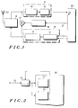
- the mobile radio telephone comprises a transmitter section 10 and a receiver section 11.
- the transmitter section has a modulator 12 and an RF section 13, and the receiver section has an RF section 14 and a demodulator and bit slicer 15.
- Connected to the RF sections 13 and 14 is a 10 MHz duplex filter 16 and a calibration loop path and mixer 17.
- Connected to the mixer 17 is a 10 MHz oscillator 18.
- a logic unit 20 is provided, to receive data from the demodulator and bit slicer 15, and provide data to the modulator 12.
- the logic unit 20 has a loop enable output 21.
- the operation of the apparatus is as follows. In normal operation, a signal modulated with data bits will be received on an antenna 22. After passing the duplex filter 16, the RF receiver section 14 and the demodulator and bit slicer 15, the received data bits will arrive at the logic unit 20.
- the bit slicer is a level detector, which provides the logic unit with both the data and the time of arrival of the data to a resolution of 90 nanoseconds. A suitable bit slicer is described in EP-A-0 371 357 of Storno A/S, which is incorporated herein by reference.
- the logic unit 20 receives the data at intervals of 1.5 microseconds.
- the radio telephone supplies data to the modulator 12 and transmits the data (accompanied by timing control signals) where the RF transmitter section 13 and the duplex filter 16.
- the logic unit starts a calibration sequence as follows.
- a loop enable is provided on output 21, which initiates oscillator 18, and calibration loop path and mixer 17 is opened, to connect the RF transmitter section 13 to the RF receiver section 14.
- the logic unit 20 generates the preamble code, and the time of arrival of the preamble code at the bit slicer 15 is measured.
- the input line sourced from the bit slicer is a synchronous input line featuring automatic capture of all bit shift times (positive and negative edges).
- the microprocessor stores the detected bit shift times. Based on the stored bit shift times, the microprocessor generates a corresponding code and compares this with the known preamble code utilising a correlation analysis algorithm, such as is described in the above referenced patent application.
- the logic unit 20 calculates the time of arrival for the preamble sequence. Because the logic unit executes the calibration sequence using the usual 34 bit preamble, locally generating that bit sequence, no special method needs to be devised for calculation of time of arrival of the looped-back signal.
- the internal free-running timer (master "watch") of the microprocessor has the same resolution and all input and output timing is related to that watch.
- FIG. 2 there is shown a microprocessor 30 and a fine resolution delay unit 31. There is also shown an input data bus 33 from the bit slicer 15, a high speed input 34 for time capture and an input 35 for fine time capture.
- the received data, and the information indicating its time of arrival appears on data bus 33.
- This data bus gives the time of arrival of the signal to a resolution of 188 nanoseconds.
- the four least significant bits are passed to input 35 where they are passed to a time capture register (not shown).
- This register provides a fine time resolution value. That value is used as a 1/8-fraction sub-specification of the time of arrival of the preamble code, and is included in the calculation of time of arrival by means of the correlation algorithm.
- the processor can internally compensate for time errors to a resolution of 1.5 microseconds. Compensation to a finer resolution is implemented by delay unit 31.
- the four least significant bits of the measured delay are added in delay unit 31 to the signal on bus 33 by a simple addition operation. This has the effect that to the microprocessor 30, it appears that the received signal is delayed by that amount.
- the time by which delay unit 31 can delay the signal ranges from 0 to 7/8 of the 1.5 microsecond internal microprocessor period. This is the value loaded by the microprocessor on its high speed input.
- the microprocessor 30 times all its output operations on a high speed output (not shown) from this measured time. Those output operations are executed a whole number of internal clock counts from the time provided on the input.
- delay unit 31 During the time measurement, a delay of 0 is loaded into delay unit 31.
- the time delay unit 31 (and time capture register) can be implemented in software or hardware.
Landscapes
- Engineering & Computer Science (AREA)
- Computer Networks & Wireless Communication (AREA)
- Signal Processing (AREA)
- Human Computer Interaction (AREA)
- Mobile Radio Communication Systems (AREA)
- Input Circuits Of Receivers And Coupling Of Receivers And Audio Equipment (AREA)
- Transceivers (AREA)
- Synchronisation In Digital Transmission Systems (AREA)
- Devices For Checking Fares Or Tickets At Control Points (AREA)
- Transmitters (AREA)
- Liquid Developers In Electrophotography (AREA)
Claims (5)
- Emetteur-récepteur radio comprenant une section récepteur (11), un section émetteur (10), une unité de commande (20, 30) servant à commander le positionnement temporel des émissions et un moyen (20 ) servant à produire un signal prédéterminé et à l'envoyer via la section émetteur (10), caractérise par :
un moyen servant à renvoyer en retour le signal prédéterminé via la section récepteur (11), un moyen (20, 30, 31, 34, 35) servant à mesurer le retard présent dans le signal, et un moyen, contenu à l'intérieur de l'unité de commande (20, 30), servant à faire avancer le positionnement temporel des émissions d'une quantité correpondant au retard mesuré, de maière à compenser les retards existant dans les sections récepteur (11 ) et émetteur (10). - Emetteur-récepteur selon la revendication 1, comprenant en outre un moyen (20, 30) servant à rechercher un code prédéterminé dans les signaux radio reçus, et un moyen servant à mesurer le positionnement temporel de ce code et à commander le positionnement temporel d'émissions ultérieures en fonction de celui-ci, où le moyen (20) servant à produire le signal prédéterminé est destiné à produire ledit code prédéterminé.
- Emetteur-récepteur selon la revendication 1, comprenant en outre un moyen (20) servant à faire commencer la production du signal prédéterminé, la mesure du retard et la compensation du retard à intervalles prédéterminés, indépendamment du fait qu'une communication bidirectionelle est en cours ou que l'émetteur est dans un mode d'inactivité et attend des signaux entrants.
- Emetteur-récepteur selon la revendication 1, comprenant un moyen de synchronisation (20, 30, 31, 34, 35) servant à mesurer le positionnement temporel d'un code reçu et un moyen de commande (20, 30) servant à commander temporel d'émissions ultérieures en fonction de celui-ci, où le moyen servant à faire avancer le positionnement temporel des émissions est conçu pour faire avancer le temps de réception du code reçu, tel que mesuré par le moyen de synchronisation (20, 30, 31, 34, 35).
- Emetteur-récepteur selon la revendication 1, où l'unité de commande (20, 30) a pour fonction de commander le positionnement des émissions avec une résolution correspondant à une durée minimale prédéterminée, et un moyen de synchronisation à résolution fine est prévue, qui comprend:
une horloge possédant une période d'horloge qui est sensiblement inférieure à ladite durée minimale prédéterminé un moyen retardateur destiné à fixer un temps de retard égal à un nombre variable de périodes de l'horloge, et un moyen servant à retarder dudit temps de retard les opérations de l'unité de commande, de manière à obtenir une commande du positionnement temporel des émissions avec une résolution plus grande que ladite durée minimale prédéterminée.
Priority Applications (1)
| Application Number | Priority Date | Filing Date | Title |
|---|---|---|---|
| AT89121330T ATE100655T1 (de) | 1988-11-28 | 1989-11-17 | Verzoegerungszeitausgleich in einem funk-senderempf|nger. |
Applications Claiming Priority (2)
| Application Number | Priority Date | Filing Date | Title |
|---|---|---|---|
| GB888827733A GB8827733D0 (en) | 1988-11-28 | 1988-11-28 | Radio transceiver |
| GB8827733 | 1988-11-28 |
Publications (3)
| Publication Number | Publication Date |
|---|---|
| EP0371358A2 EP0371358A2 (fr) | 1990-06-06 |
| EP0371358A3 EP0371358A3 (fr) | 1991-05-08 |
| EP0371358B1 true EP0371358B1 (fr) | 1994-01-19 |
Family
ID=10647580
Family Applications (1)
| Application Number | Title | Priority Date | Filing Date |
|---|---|---|---|
| EP89121330A Expired - Lifetime EP0371358B1 (fr) | 1988-11-28 | 1989-11-17 | Compensation du temps de retard dans un émetteur-récepteur radio |
Country Status (9)
| Country | Link |
|---|---|
| EP (1) | EP0371358B1 (fr) |
| JP (1) | JP3099363B2 (fr) |
| AT (1) | ATE100655T1 (fr) |
| AU (1) | AU615368B2 (fr) |
| CA (1) | CA2003947A1 (fr) |
| DE (1) | DE68912534T2 (fr) |
| GB (1) | GB8827733D0 (fr) |
| IE (1) | IE893770L (fr) |
| WO (1) | WO1990006635A1 (fr) |
Cited By (1)
| Publication number | Priority date | Publication date | Assignee | Title |
|---|---|---|---|---|
| US7839960B2 (en) | 1990-06-25 | 2010-11-23 | Qualcomm Incorporated | System and method for generating signal waveforms in a CDMA cellular telephone system |
Families Citing this family (6)
| Publication number | Priority date | Publication date | Assignee | Title |
|---|---|---|---|---|
| US5103459B1 (en) * | 1990-06-25 | 1999-07-06 | Qualcomm Inc | System and method for generating signal waveforms in a cdma cellular telephone system |
| JPH06284085A (ja) * | 1993-03-25 | 1994-10-07 | Toshiba Corp | ディジタル無線通信装置 |
| FI92966C (fi) * | 1993-05-18 | 1995-01-25 | Nokia Telecommunications Oy | Menetelmä ja järjestely tukiaseman kunnon mittaamiseksi |
| KR100706410B1 (ko) | 2006-03-17 | 2007-04-10 | 주식회사 팬택앤큐리텔 | 업링크 동기화 방법과 그 방법을 채용한 통신 시스템 |
| JP2015037307A (ja) * | 2013-08-16 | 2015-02-23 | 富士通株式会社 | 無線通信装置及び送信タイミング調整プログラム |
| EP4293923B1 (fr) | 2021-02-15 | 2026-03-25 | Furuno Electric Co., Ltd. | Dispositif de détection de synchronisation et procédé de détection de synchronisation |
Family Cites Families (4)
| Publication number | Priority date | Publication date | Assignee | Title |
|---|---|---|---|---|
| DE2432449A1 (de) * | 1974-07-06 | 1976-01-22 | Bosch Gmbh Robert | Funkuebertragungssystem, bei dem der funkverkehr ueber eine einzige traegerfrequenz abgewickelt wird |
| US4653076A (en) * | 1984-03-23 | 1987-03-24 | Sangamo Weston, Inc. | Timing signal correction system for use in direct sequence spread signal receiver |
| US4696052A (en) * | 1985-12-31 | 1987-09-22 | Motorola Inc. | Simulcast transmitter apparatus having automatic synchronization capability |
| US4787095A (en) * | 1987-03-03 | 1988-11-22 | Advanced Micro Devices, Inc. | Preamble search and synchronizer circuit |
-
1988
- 1988-11-28 GB GB888827733A patent/GB8827733D0/en active Pending
-
1989
- 1989-11-17 AT AT89121330T patent/ATE100655T1/de not_active IP Right Cessation
- 1989-11-17 DE DE68912534T patent/DE68912534T2/de not_active Expired - Fee Related
- 1989-11-17 EP EP89121330A patent/EP0371358B1/fr not_active Expired - Lifetime
- 1989-11-24 JP JP02500974A patent/JP3099363B2/ja not_active Expired - Fee Related
- 1989-11-24 AU AU47406/90A patent/AU615368B2/en not_active Ceased
- 1989-11-24 WO PCT/DK1989/000281 patent/WO1990006635A1/fr not_active Ceased
- 1989-11-27 IE IE893770A patent/IE893770L/xx unknown
- 1989-11-27 CA CA002003947A patent/CA2003947A1/fr not_active Abandoned
Cited By (1)
| Publication number | Priority date | Publication date | Assignee | Title |
|---|---|---|---|---|
| US7839960B2 (en) | 1990-06-25 | 2010-11-23 | Qualcomm Incorporated | System and method for generating signal waveforms in a CDMA cellular telephone system |
Also Published As
| Publication number | Publication date |
|---|---|
| ATE100655T1 (de) | 1994-02-15 |
| EP0371358A3 (fr) | 1991-05-08 |
| AU615368B2 (en) | 1991-09-26 |
| IE893770L (en) | 1990-05-28 |
| WO1990006635A1 (fr) | 1990-06-14 |
| EP0371358A2 (fr) | 1990-06-06 |
| JPH03503352A (ja) | 1991-07-25 |
| DE68912534D1 (de) | 1994-03-03 |
| CA2003947A1 (fr) | 1990-05-28 |
| JP3099363B2 (ja) | 2000-10-16 |
| AU4740690A (en) | 1990-06-26 |
| GB8827733D0 (en) | 1988-12-29 |
| DE68912534T2 (de) | 1994-05-19 |
Similar Documents
| Publication | Publication Date | Title |
|---|---|---|
| US6373434B1 (en) | Distance detecting method and its apparatus | |
| US4218654A (en) | Space diversity system in TDMA communication system | |
| EP1273112B1 (fr) | Synchronisation d'avance et de deviation temporelles | |
| CA1258324A (fr) | Dispositif de synchronisation pouvant etablir la synchronisation sans transmission d'information de distance entre les stations terriennes de controle et locale | |
| USRE37870E1 (en) | CDMA/TDD radio communication system | |
| US5216429A (en) | Position measuring system using pseudo-noise signal transmission and reception | |
| US5152006A (en) | Receiver controller method and apparatus | |
| US5613195A (en) | Burst output timing control system in satellite communication system | |
| CA2071556C (fr) | Methode et dispositif de controle pour emetteur-recepteur amrt | |
| EP0371358B1 (fr) | Compensation du temps de retard dans un émetteur-récepteur radio | |
| US6239720B1 (en) | Circuit and method for providing simultaneous transmission of page data in a paging system | |
| US20030053439A1 (en) | TDMA radio terminal capable of adjusting transmit timing by using measured delay time | |
| JPH08122425A (ja) | 位置標定システムの独立同期化方式、位置標定システムの到達時間測定方式、及び位置標定システムの位置標定誤差補正方式 | |
| US5442635A (en) | Method for dividing a frame structure in a mobile station | |
| WO1992013395A1 (fr) | Procede et appareil de commande d'un recepteur | |
| JP2962277B2 (ja) | Tdma送信タイミング設定方式 | |
| JPS58162148A (ja) | 自動位相補償方式 | |
| RU2173026C2 (ru) | Схема для задержки опорного сигнала синхронизации из приемного устройства глобальной спутниковой системы радиоопределения, способ одновременной передачи поискового вызова | |
| JP2005117585A (ja) | ダイバーシティ送信機 | |
| JPH10145845A (ja) | 移動通信システム | |
| JPH0648795B2 (ja) | Ss−tdma衛星通信のバ−スト同期方式 | |
| GB2327018A (en) | Control system synchronisation | |
| JPH02164151A (ja) | スペクトラム拡散通信装置 | |
| JPH07212301A (ja) | 時分割多重通信方法 | |
| JPH0728255B2 (ja) | 地球局通信装置 |
Legal Events
| Date | Code | Title | Description |
|---|---|---|---|
| PUAI | Public reference made under article 153(3) epc to a published international application that has entered the european phase |
Free format text: ORIGINAL CODE: 0009012 |
|
| AK | Designated contracting states |
Kind code of ref document: A2 Designated state(s): AT BE CH DE ES FR GB GR IT LI LU NL SE |
|
| PUAL | Search report despatched |
Free format text: ORIGINAL CODE: 0009013 |
|
| AK | Designated contracting states |
Kind code of ref document: A3 Designated state(s): AT BE CH DE ES FR GB GR IT LI LU NL SE |
|
| 17P | Request for examination filed |
Effective date: 19910930 |
|
| 17Q | First examination report despatched |
Effective date: 19930506 |
|
| RAP1 | Party data changed (applicant data changed or rights of an application transferred) |
Owner name: MOTOROLA A/S |
|
| GRAA | (expected) grant |
Free format text: ORIGINAL CODE: 0009210 |
|
| AK | Designated contracting states |
Kind code of ref document: B1 Designated state(s): AT BE CH DE ES FR GB GR IT LI LU NL SE |
|
| PG25 | Lapsed in a contracting state [announced via postgrant information from national office to epo] |
Ref country code: IT Free format text: LAPSE BECAUSE OF FAILURE TO SUBMIT A TRANSLATION OF THE DESCRIPTION OR TO PAY THE FEE WITHIN THE PRE;WARNING: LAPSES OF ITALIAN PATENTS WITH EFFECTIVE DATE BEFORE 2007 MAY HAVE OCCURRED AT ANY TIME BEFORE 2007. THE CORRECT EFFECTIVE DATE MAY BE DIFFERENT FROM THE ONE RECORDED.SCRIBED TIME-LIMIT Effective date: 19940119 Ref country code: BE Effective date: 19940119 Ref country code: LI Effective date: 19940119 Ref country code: CH Effective date: 19940119 Ref country code: AT Effective date: 19940119 Ref country code: SE Effective date: 19940119 Ref country code: GR Free format text: LAPSE BECAUSE OF FAILURE TO SUBMIT A TRANSLATION OF THE DESCRIPTION OR TO PAY THE FEE WITHIN THE PRESCRIBED TIME-LIMIT Effective date: 19940119 Ref country code: ES Free format text: THE PATENT HAS BEEN ANNULLED BY A DECISION OF A NATIONAL AUTHORITY Effective date: 19940119 Ref country code: NL Effective date: 19940119 |
|
| REF | Corresponds to: |
Ref document number: 100655 Country of ref document: AT Date of ref document: 19940215 Kind code of ref document: T |
|
| REF | Corresponds to: |
Ref document number: 68912534 Country of ref document: DE Date of ref document: 19940303 |
|
| REG | Reference to a national code |
Ref country code: CH Ref legal event code: PL |
|
| ET | Fr: translation filed | ||
| NLV1 | Nl: lapsed or annulled due to failure to fulfill the requirements of art. 29p and 29m of the patents act | ||
| PLBE | No opposition filed within time limit |
Free format text: ORIGINAL CODE: 0009261 |
|
| STAA | Information on the status of an ep patent application or granted ep patent |
Free format text: STATUS: NO OPPOSITION FILED WITHIN TIME LIMIT |
|
| 26N | No opposition filed | ||
| PGFP | Annual fee paid to national office [announced via postgrant information from national office to epo] |
Ref country code: GB Payment date: 19970930 Year of fee payment: 9 |
|
| PGFP | Annual fee paid to national office [announced via postgrant information from national office to epo] |
Ref country code: FR Payment date: 19971015 Year of fee payment: 9 |
|
| PGFP | Annual fee paid to national office [announced via postgrant information from national office to epo] |
Ref country code: DE Payment date: 19971023 Year of fee payment: 9 |
|
| PG25 | Lapsed in a contracting state [announced via postgrant information from national office to epo] |
Ref country code: GB Free format text: LAPSE BECAUSE OF NON-PAYMENT OF DUE FEES Effective date: 19981117 Ref country code: LU Free format text: LAPSE BECAUSE OF NON-PAYMENT OF DUE FEES Effective date: 19981117 |
|
| PGFP | Annual fee paid to national office [announced via postgrant information from national office to epo] |
Ref country code: LU Payment date: 19990112 Year of fee payment: 9 |
|
| GBPC | Gb: european patent ceased through non-payment of renewal fee |
Effective date: 19981117 |
|
| PG25 | Lapsed in a contracting state [announced via postgrant information from national office to epo] |
Ref country code: FR Free format text: LAPSE BECAUSE OF NON-PAYMENT OF DUE FEES Effective date: 19990730 |
|
| REG | Reference to a national code |
Ref country code: FR Ref legal event code: ST |
|
| PG25 | Lapsed in a contracting state [announced via postgrant information from national office to epo] |
Ref country code: DE Free format text: LAPSE BECAUSE OF NON-PAYMENT OF DUE FEES Effective date: 19990901 |
|
| P01 | Opt-out of the competence of the unified patent court (upc) registered |
Effective date: 20230520 |