EP0371407A2 - Compresseur d'air équipé d'une soupape annulaire - Google Patents
Compresseur d'air équipé d'une soupape annulaire Download PDFInfo
- Publication number
- EP0371407A2 EP0371407A2 EP89121745A EP89121745A EP0371407A2 EP 0371407 A2 EP0371407 A2 EP 0371407A2 EP 89121745 A EP89121745 A EP 89121745A EP 89121745 A EP89121745 A EP 89121745A EP 0371407 A2 EP0371407 A2 EP 0371407A2
- Authority
- EP
- European Patent Office
- Prior art keywords
- valve
- ring valve
- cylinder head
- fluid
- cylinder
- Prior art date
- Legal status (The legal status is an assumption and is not a legal conclusion. Google has not performed a legal analysis and makes no representation as to the accuracy of the status listed.)
- Withdrawn
Links
Images



Classifications
-
- F—MECHANICAL ENGINEERING; LIGHTING; HEATING; WEAPONS; BLASTING
- F04—POSITIVE - DISPLACEMENT MACHINES FOR LIQUIDS; PUMPS FOR LIQUIDS OR ELASTIC FLUIDS
- F04B—POSITIVE-DISPLACEMENT MACHINES FOR LIQUIDS; PUMPS
- F04B39/00—Component parts, details, or accessories, of pumps or pumping systems specially adapted for elastic fluids, not otherwise provided for in, or of interest apart from, groups F04B25/00 - F04B37/00
- F04B39/10—Adaptations or arrangements of distribution members
- F04B39/102—Adaptations or arrangements of distribution members the members being disc valves
- F04B39/1033—Adaptations or arrangements of distribution members the members being disc valves annular disc valves
-
- F—MECHANICAL ENGINEERING; LIGHTING; HEATING; WEAPONS; BLASTING
- F04—POSITIVE - DISPLACEMENT MACHINES FOR LIQUIDS; PUMPS FOR LIQUIDS OR ELASTIC FLUIDS
- F04B—POSITIVE-DISPLACEMENT MACHINES FOR LIQUIDS; PUMPS
- F04B49/00—Control, e.g. of pump delivery, or pump pressure of, or safety measures for, machines, pumps, or pumping installations, not otherwise provided for, or of interest apart from, groups F04B1/00 - F04B47/00
- F04B49/22—Control, e.g. of pump delivery, or pump pressure of, or safety measures for, machines, pumps, or pumping installations, not otherwise provided for, or of interest apart from, groups F04B1/00 - F04B47/00 by means of valves
- F04B49/225—Control, e.g. of pump delivery, or pump pressure of, or safety measures for, machines, pumps, or pumping installations, not otherwise provided for, or of interest apart from, groups F04B1/00 - F04B47/00 by means of valves with throttling valves or valves varying the pump inlet opening or the outlet opening
-
- Y—GENERAL TAGGING OF NEW TECHNOLOGICAL DEVELOPMENTS; GENERAL TAGGING OF CROSS-SECTIONAL TECHNOLOGIES SPANNING OVER SEVERAL SECTIONS OF THE IPC; TECHNICAL SUBJECTS COVERED BY FORMER USPC CROSS-REFERENCE ART COLLECTIONS [XRACs] AND DIGESTS
- Y10—TECHNICAL SUBJECTS COVERED BY FORMER USPC
- Y10T—TECHNICAL SUBJECTS COVERED BY FORMER US CLASSIFICATION
- Y10T137/00—Fluid handling
- Y10T137/7722—Line condition change responsive valves
- Y10T137/7837—Direct response valves [i.e., check valve type]
- Y10T137/7859—Single head, plural ports in parallel
- Y10T137/7861—Annular head
Definitions
- the present invention relates generally to valves for controlling fluid flow that operate to permit and disrupt fluid flow automatically, and particularly to ring-type valve structures, including biasing means, used as air inlet valves and exhaust valves in high pressure gas compressors and fluid pumps.
- Ring-type valves per se are generally well known in the prior art, and have a wide acceptance in use for air compressors and pumps. Basically, these ring-type valves are opened and closed by pressure differential on opposite sides of the ring valve. It is also heretofore known to include biasing of spring devices along with such ring valves in order to accurately control valve movement upon a pressure differential which is above the spring force of the spring selected in each case. In this way, the valve is opened or closed only upon reaching a predetermined pressure differential dependent on the spring properties of the spring chosen, and the mass of the valve, wherein the valve action can be predicted.
- the Herzmark reference is directed to an air compressor which utilizes ring valves to control air flow between low stage and high stage air compression cylinders.
- Herzmark also discloses the use of spring washers that are freely supported to bias the ring valves in a desired position. This type of spring washer and ring valve requires additional supporting structure to retain the spring washer that decreases the efficiency of the air compressor by lowering the compression volume of each cylinder at the end of the suction stroke, and increases the cost, weight and complexity of the valve assembly.
- a valve assembly and reciprocating type fluid pump having a piston cylinder and a cylinder head together which define a fluid chamber.
- a first ring valve having a seal surface on one side is disposed within the fluid chamber adjacent to the cylinder head to close at least one fluid intake passage.
- a bias means is provided for urging the first ring valve against a seat on the head by abutting the ring valve on a side opposite from the seal surface, and the bias means includes a peripheral region which is connected to the fluid pump and retains the first ring valve between the cylinder head and the bias means.
- a primary object of the present invention to provide a fluid pump device such as an air compressor that has an increased volumetric efficiency while at the same time reducing costs, weight and complexity.
- valve assembly and a portion of an air compressor or fluid pump.
- the remaining description will refer to the unit as a compressor and valve assembly with the understanding that the valve assembly can be used on any similar type fluid pump.
- a reciprocating type compressor including a piston cylinder 10 and a cylinder head 12.
- a piston 11 driven by a conventional crankshaft 13 or other suitable means.
- the piston, the piston cylinder bore and the head define a fluid chamber, more particularly a gas compression chamber 14, the volume of which is varied by movement of the piston.
- the head 12 of the FIG. 1 embodiment comprises a two part assembly with a plate 16 and a body 18 along with a cover plate 20. Together, these elements define the air flow passages for air intake and exhaust.
- At least one air intake 22 is provided in plate 16 which opens into a gallery 24 also formed in plate 16 and which provides a circular channel on the bottom face of plate 16 for better distribution of intake air into the gas compression chamber 14 by way of an intake valve, as hereinafter described.
- the gallery 24 is further defined on the outer face of the plate 16 by an outer circular ridge 26 and an inner circular ridge 28.
- the outer and inner ridges together serve as a valve seat for the intake valve comprised of a ring valve 30.
- the ring valve 30 includes a seal surface on one side thereof to contact the valve seat and thereby close off the intake air from the gas compression chamber 14.
- Ring valve 30 is illustrated in FIG. 5 and is dimensioned so as to completely cover the gallery 24 as defined between the inner and outer ridges 28 and 26 respectively.
- the ring valve and gallery together present a simple design with a high flow area.
- the spring element 32 Disposed adjacent to the ring valve 30 is a spring element 32 to bias the ring valve 30 against its seat defined by ridges 26 and 28.
- the spring element 32 seen most clearly in FIG. 4 and 6, comprises a substantially flat plate-like member of rectangular configuration with a circular opening therein. Within the circular opening are four spring arms 34 which are connected to the spring element 32 at 36. Preferably, the spring arms 34 can be provided on the spring element wherein four are used in the preferred embodiment.
- the spring arms 34 extend from connection points 36 toward distal ends thereof at 38, and the spring arms also extend outward from the plane of the spring element 32 in increasing distance toward the distal ends. As shown in FIG. 6, the spring arms 34 extend out of the plane of the page toward the viewer with the distal ends 38 of each spring arm out substantially the same distance.
- the spring element 34 further comprises a substantially flat peripheral region 40 completely surrounding the spring element 32.
- This peripheral region 40 serves the dual purpose of connecting the spring element 32 to the air compressor to retain the ring valve 30 between the head and the spring element, and also to serve as a head gasket between the head 12 and the piston cylinder 10 to seal the gas compression chamber 14 from outside air.
- the spring element 32 along with spring arms 34 and the peripheral region 40 obtains a very simple construction which forces the ring valve 32 in operative position as well as sealing the gas compression chamber.
- Holes 42 are also provided through the peripheral region to facilitate bolts (not shown) for securing the head to the piston cylinder.
- FIGS. 2 and 3 there is an exhaust passage 44 through plate 16 of head 12 which is closed off by a second ring valve 46.
- the ring valve 46 is provided on the opposite side of the head plate 16 and contacts a seat 48 on the plate 16.
- the second valve 46 is biased toward the seat in a closed position by a spring means 50.
- the spring means 50 can be any conventional spring such as a single spiral spring, a plurality of small spiral springs, a leaf spring or springs, or a spring device similar to that shown in FIG. 4 without the gasket region.
- the ring valve 46 is similar to that shown in FIG. 3, but is dimensioned to seat entirely with seat 48 and seal the exhaust passages from the gas compression chamber 14.
- valve assembly and air compressor The operation of the valve assembly and air compressor is described as follows, starting at the point in a reciprocating compressor wherein the piston 11 is at top dead center. As the piston is moved away from the head, suction is created in the gas compression chamber 14 thus opening ring valve 30 against the bias of spring arms 34. Air thus enters the compression chamber by way of intake 22, gallery 24 and ring valve 30. When the piston reaches bottom dead center, the bias of the spring arms 34 effectively closes off the intake 22 and seals the compression chamber from the intake. The present invention thus operates to close off the intake air immediately at the bottom dead center of the suction stroke without having to rely on pressure differential to operate the ring valve.
- the intake ring valve 30 remains closed and the pressure within the compression chamber opens the exhaust ring valve 46 against the bias of spring means 50.
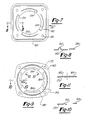
- FIGS. 7 and 8 A further embodiment of a spring element is shown in FIGS. 7 and 8 at 132.
- This embodiment is basically the same as the spring element 32 including spring arms 134 and mounting holes 142 with an additional feature to improve the sealing capability of the gasket portion at the peripheral region 140.
- a crimp 150 is provided in the peripheral region 140 to extend along the peripheral region.
- FIG. 8 simply shows a cross section along line 8-8 of FIG. 7 with the crimp 150 extending above the substantially flat plane of the peripheral region 140.
- the crimp 150 is positioned such that when the peripheral region is used as a head gasket between the piston cylinder and head, the crimp is subjected to the force applied by the head bolts and is compressed between the piston cylinder and the head, thereby increasing the seal of the gasket. It is also contemplated to use a bead of sealant along with the gasket to increase the seal of either the gasket with or without the crimp. Any type conventional sealant such as RTV can be used.
- FIGS 9-11 A still further embodiment of a spring element is shown in FIGS 9-11 at 162.
- This element is still basically the same as the spring element 32, but including integral spring arms 164 and mounting holes 172 with an additional feature to improve the sealing capacity of the gasket portion, as in the embodiment shown in FIG. 7, at the peripheral region 170.
- a crimp 180 is provided in the peripheral region 170 to extend along the peripheral region.
- FIG. 10 simply shows a cross-section along line 10-10 of FIG. 9, with the crimp 180 extending above the substantially flat plane of the peripheral region 170.
- the crimp 180 is positioned such that when the peripheral region is used as a head gasket between the piston cylinder and head, the crimp is subjected to the force applied by the head bolts, and is compressed between the piston cylinder and the head, thereby increasing the seal of the gasket, as with the embodiment shown in FIG. 7. It is again contemplated to use a bead of sealant along with the gasket to increase the seal of either the gasket with or without the crimp. As before, any type of conventional sealant such as RTV can be used.
- a high silicon aluminum alloy with more than 11 per cent silicon is preferably used to form the plate 16. It has been found that such a high silicon plate with the valve seats 26, 28 and 48 formed thereon has an increased hardness and increased wear resistance. Preferably, the plate is die cast with an alloy of approximately 18% silicon.
- valve assembly of the present invention is applicable to air compressors of any size that use a reciprocating motion to compress air, as well as to the compression of any other gases, such as refrigerant compressors. It is also within the scope of the present invention to use such a valve assembly on other types of fluids other than gases which may, or may not, be compressible, such as for liquid pumps.
- our improved compressor can accept an external loading unloading device 121 to enable it to be used in compressor unloading systems preferably of the type disclosed in our co-pending United States Letters Patent application entitled "Air Compressor Unloader System” filed on even date herewith and under common ownership with the present application.
- an air manifold 123 adapted to fit over and enclose the intake 122. of the ring valve type air compressor 120.
- a valve body 124 having an inlet 125 is mounted to the air manifold 123 to completely enclose the internal cavity 123a provided in said manifold.
- a cylinder 126 is formed in the valve body 124 in which is sealingly but slidably fitted a piston 127 having a piston rod 129 fixedly mounted thereto.
- a valve 131 is retained on the piston rod between the valve unloader spring 130 and the enlarged end 129a of said piston rod.
- the valve 131 will also reciprocate opening and closing the internal cavitey 123 of the air manifold, and therefore blocking and unblocking the fluid communication between the inlet 122 of the air compressor and the atmosphere.
- valve spring 132 is interposed between the valve 131 and the manifold 123.
Landscapes
- Engineering & Computer Science (AREA)
- Mechanical Engineering (AREA)
- General Engineering & Computer Science (AREA)
- Compressor (AREA)
Applications Claiming Priority (2)
| Application Number | Priority Date | Filing Date | Title |
|---|---|---|---|
| US07/278,225 US5022832A (en) | 1988-11-30 | 1988-11-30 | Ring valve type air compressor |
| US278225 | 1988-11-30 |
Publications (2)
| Publication Number | Publication Date |
|---|---|
| EP0371407A2 true EP0371407A2 (fr) | 1990-06-06 |
| EP0371407A3 EP0371407A3 (fr) | 1990-10-17 |
Family
ID=23064181
Family Applications (1)
| Application Number | Title | Priority Date | Filing Date |
|---|---|---|---|
| EP19890121745 Withdrawn EP0371407A3 (fr) | 1988-11-30 | 1989-11-24 | Compresseur d'air équipé d'une soupape annulaire |
Country Status (4)
| Country | Link |
|---|---|
| US (1) | US5022832A (fr) |
| EP (1) | EP0371407A3 (fr) |
| JP (1) | JPH02277978A (fr) |
| BR (1) | BR8906048A (fr) |
Cited By (3)
| Publication number | Priority date | Publication date | Assignee | Title |
|---|---|---|---|---|
| WO1995011384A1 (fr) * | 1993-10-18 | 1995-04-27 | Freios Varga S/A | Dispositif de regulation pour compresseurs asservis des systemes de freins pneumatiques d'automobiles |
| EP1404971A4 (fr) * | 2001-06-19 | 2005-06-08 | James E Cook | Pompe a piston plongeur simplex a double effet avec soupapes bidirectionnelles |
| CN109268226A (zh) * | 2018-10-27 | 2019-01-25 | 上海国液压气动有限公司 | 一种冷气一级增压泵 |
Families Citing this family (16)
| Publication number | Priority date | Publication date | Assignee | Title |
|---|---|---|---|---|
| US5277560A (en) * | 1991-06-26 | 1994-01-11 | Holset Engineering Company, Inc. | Ring valve type air compressor with deformable ring valves |
| US5213487A (en) * | 1991-06-26 | 1993-05-25 | Holset Engineering Company, Inc. | Ring valve type air compressor with deformable ring valves |
| JPH07293440A (ja) * | 1994-04-27 | 1995-11-07 | Aisin Seiki Co Ltd | 圧縮機 |
| US6443713B1 (en) * | 2000-10-18 | 2002-09-03 | Thomas Industries Inc. | Diaphragm pump with support ring |
| DE10125420C1 (de) * | 2001-05-25 | 2002-10-24 | Pnp Luftfedersysteme Gmbh | Mehrstufiger Kolbenverdichter |
| DE20108696U1 (de) * | 2001-05-25 | 2001-08-30 | PNP Luftfedersysteme GmbH, 19089 Crivitz | Mehrstufiger Kolbenverdichter |
| JP2006266543A (ja) * | 2005-03-22 | 2006-10-05 | Fuji Koki Corp | 電磁弁一体型膨張弁 |
| DE102011002982B4 (de) | 2011-01-21 | 2022-05-25 | Robert Bosch Gmbh | Federelement und korrespondierende Kolbenpumpe zur Förderung von Fluiden |
| BRPI1103647A2 (pt) * | 2011-07-07 | 2013-07-02 | Whirlpool Sa | disposiÇço entre componentes de compressor linear |
| BRPI1103447A2 (pt) * | 2011-07-19 | 2013-07-09 | Whirlpool Sa | feixe de molas para compressor e compressor provido de feixe de molas |
| BRPI1104172A2 (pt) * | 2011-08-31 | 2015-10-13 | Whirlpool Sa | compressor linear baseado em mecanismo oscilatório ressonante |
| US20130121860A1 (en) * | 2011-11-10 | 2013-05-16 | Gene Bluhm | Retrofit of a reciprocating compressor with a concentric valve |
| US20140271250A1 (en) * | 2013-03-15 | 2014-09-18 | Cameron International Corporation | Compression System and Method Having Co-Axial Flow Device |
| JP6426396B2 (ja) * | 2014-08-07 | 2018-11-21 | ザマ・ジャパン株式会社 | 逆止弁 |
| KR102259650B1 (ko) | 2016-05-03 | 2021-06-02 | 엘지전자 주식회사 | 리니어 압축기 |
| US11035491B2 (en) | 2017-07-03 | 2021-06-15 | Continental Automotive Systems, Inc. | Fuel pump solenoid having hydraulic damping |
Family Cites Families (7)
| Publication number | Priority date | Publication date | Assignee | Title |
|---|---|---|---|---|
| US1796796A (en) * | 1929-09-14 | 1931-03-17 | Ingersoll Rand Co | Compressor unloader |
| US2035854A (en) * | 1934-06-11 | 1936-03-31 | Walter W Williams | Compressor |
| US2036799A (en) * | 1935-06-19 | 1936-04-07 | Gen Electric | Compressor |
| US2556623A (en) * | 1946-03-26 | 1951-06-12 | Lipkau Maximiliano Alvarez | Means for automatically opening and closing a compressor intake |
| DE1809954C3 (de) * | 1968-11-20 | 1975-10-16 | Woma-Apparatebau Wolfgang Maasberg & Co Gmbh, 4140 Rheinhausen | Ventilausbildung und deren Anordnung im Zylinderkopf einer Kolbenpumpe |
| US4045009A (en) * | 1975-11-17 | 1977-08-30 | General Motors Corporation | Energy absorbing unit with improved control valve |
| US4115044A (en) * | 1976-10-04 | 1978-09-19 | Tecumseh Products Company | Valve arrangement for compressor |
-
1988
- 1988-11-30 US US07/278,225 patent/US5022832A/en not_active Expired - Fee Related
-
1989
- 1989-11-24 EP EP19890121745 patent/EP0371407A3/fr not_active Withdrawn
- 1989-11-29 JP JP1307812A patent/JPH02277978A/ja active Pending
- 1989-11-30 BR BR898906048A patent/BR8906048A/pt unknown
Cited By (4)
| Publication number | Priority date | Publication date | Assignee | Title |
|---|---|---|---|---|
| WO1995011384A1 (fr) * | 1993-10-18 | 1995-04-27 | Freios Varga S/A | Dispositif de regulation pour compresseurs asservis des systemes de freins pneumatiques d'automobiles |
| EP1404971A4 (fr) * | 2001-06-19 | 2005-06-08 | James E Cook | Pompe a piston plongeur simplex a double effet avec soupapes bidirectionnelles |
| CN109268226A (zh) * | 2018-10-27 | 2019-01-25 | 上海国液压气动有限公司 | 一种冷气一级增压泵 |
| CN109268226B (zh) * | 2018-10-27 | 2024-04-26 | 上海国一液压气动有限公司 | 一种冷气一级增压泵 |
Also Published As
| Publication number | Publication date |
|---|---|
| JPH02277978A (ja) | 1990-11-14 |
| US5022832A (en) | 1991-06-11 |
| EP0371407A3 (fr) | 1990-10-17 |
| BR8906048A (pt) | 1990-06-19 |
Similar Documents
| Publication | Publication Date | Title |
|---|---|---|
| US5022832A (en) | Ring valve type air compressor | |
| US4723896A (en) | Compressor discharge valve assembly | |
| US5613837A (en) | Air compressor inlet and outlet valve arrangement | |
| US5147190A (en) | Increased efficiency valve system for a fluid pumping assembly | |
| US5266016A (en) | Positive stop for a suction leaf valve of a compressor | |
| EP0280264A2 (fr) | Pompe à vide à plusieurs étages | |
| US5577901A (en) | Compressor with valve unit for controlling suction and discharge of fluid | |
| US4352377A (en) | Compressor discharge valve | |
| US5174735A (en) | Low reexpansion valve system | |
| US4685489A (en) | Valve assembly and compressor modulation apparatus | |
| EP1452735A2 (fr) | Plaque à clapets pour des compresseurs à piston | |
| CA2089413A1 (fr) | Valve d'entree et de sortie de compresseur | |
| US4447193A (en) | Compressor unloader apparatus | |
| CA2537150A1 (fr) | Compresseur compact | |
| EP0522745B1 (fr) | Dispositif de soupape annulaire pour une pompe de fluide à mouvement alternatif | |
| US5213487A (en) | Ring valve type air compressor with deformable ring valves | |
| US20040161352A1 (en) | Shaped valve seats in displacement compressors | |
| EP0860607A3 (fr) | Méchanisme de soupape d'admission et d'échappement pour un compresseur | |
| EP0240278A2 (fr) | Compresseur de gaz | |
| KR100578374B1 (ko) | 밀폐형 압축기의 밸브장치 | |
| JPH0418148B2 (fr) | ||
| US3358908A (en) | Fluid compressor | |
| KR200267901Y1 (ko) | 밀폐형 압축기의 토출밸브장치 | |
| JPH0645664Y2 (ja) | 往復ポンプ | |
| JPS6332942Y2 (fr) |
Legal Events
| Date | Code | Title | Description |
|---|---|---|---|
| PUAI | Public reference made under article 153(3) epc to a published international application that has entered the european phase |
Free format text: ORIGINAL CODE: 0009012 |
|
| AK | Designated contracting states |
Kind code of ref document: A2 Designated state(s): DE ES FR GB IT |
|
| PUAL | Search report despatched |
Free format text: ORIGINAL CODE: 0009013 |
|
| AK | Designated contracting states |
Kind code of ref document: A3 Designated state(s): DE ES FR GB IT |
|
| STAA | Information on the status of an ep patent application or granted ep patent |
Free format text: STATUS: THE APPLICATION IS DEEMED TO BE WITHDRAWN |
|
| 18D | Application deemed to be withdrawn |
Effective date: 19910418 |