EP0371690A2 - Mécanisme de transmission - Google Patents
Mécanisme de transmission Download PDFInfo
- Publication number
- EP0371690A2 EP0371690A2 EP89312135A EP89312135A EP0371690A2 EP 0371690 A2 EP0371690 A2 EP 0371690A2 EP 89312135 A EP89312135 A EP 89312135A EP 89312135 A EP89312135 A EP 89312135A EP 0371690 A2 EP0371690 A2 EP 0371690A2
- Authority
- EP
- European Patent Office
- Prior art keywords
- wheel
- drive
- shaft
- driven
- gear
- Prior art date
- Legal status (The legal status is an assumption and is not a legal conclusion. Google has not performed a legal analysis and makes no representation as to the accuracy of the status listed.)
- Granted
Links
Images


Classifications
-
- F—MECHANICAL ENGINEERING; LIGHTING; HEATING; WEAPONS; BLASTING
- F16—ENGINEERING ELEMENTS AND UNITS; GENERAL MEASURES FOR PRODUCING AND MAINTAINING EFFECTIVE FUNCTIONING OF MACHINES OR INSTALLATIONS; THERMAL INSULATION IN GENERAL
- F16H—GEARING
- F16H57/00—General details of gearing
- F16H57/02—Gearboxes; Mounting gearing therein
- F16H57/033—Series gearboxes, e.g. gearboxes based on the same design being available in different sizes or gearboxes using a combination of several standardised units
-
- F—MECHANICAL ENGINEERING; LIGHTING; HEATING; WEAPONS; BLASTING
- F16—ENGINEERING ELEMENTS AND UNITS; GENERAL MEASURES FOR PRODUCING AND MAINTAINING EFFECTIVE FUNCTIONING OF MACHINES OR INSTALLATIONS; THERMAL INSULATION IN GENERAL
- F16H—GEARING
- F16H1/00—Toothed gearings for conveying rotary motion
- F16H1/02—Toothed gearings for conveying rotary motion without gears having orbital motion
- F16H1/20—Toothed gearings for conveying rotary motion without gears having orbital motion involving more than two intermeshing members
-
- F—MECHANICAL ENGINEERING; LIGHTING; HEATING; WEAPONS; BLASTING
- F16—ENGINEERING ELEMENTS AND UNITS; GENERAL MEASURES FOR PRODUCING AND MAINTAINING EFFECTIVE FUNCTIONING OF MACHINES OR INSTALLATIONS; THERMAL INSULATION IN GENERAL
- F16H—GEARING
- F16H7/00—Gearings for conveying rotary motion by endless flexible members
- F16H7/02—Gearings for conveying rotary motion by endless flexible members with belts; with V-belts
- F16H7/023—Gearings for conveying rotary motion by endless flexible members with belts; with V-belts with belts having a toothed contact surface or regularly spaced bosses or hollows for slipless or nearly slipless meshing with complementary profiled contact surface of a pulley
-
- Y—GENERAL TAGGING OF NEW TECHNOLOGICAL DEVELOPMENTS; GENERAL TAGGING OF CROSS-SECTIONAL TECHNOLOGIES SPANNING OVER SEVERAL SECTIONS OF THE IPC; TECHNICAL SUBJECTS COVERED BY FORMER USPC CROSS-REFERENCE ART COLLECTIONS [XRACs] AND DIGESTS
- Y10—TECHNICAL SUBJECTS COVERED BY FORMER USPC
- Y10T—TECHNICAL SUBJECTS COVERED BY FORMER US CLASSIFICATION
- Y10T74/00—Machine element or mechanism
- Y10T74/19—Gearing
- Y10T74/19642—Directly cooperating gears
- Y10T74/19679—Spur
- Y10T74/19684—Motor and gearing
Definitions
- the present invention relates to a drive transmission mechanism for transmitting the rotational driving force of a drive shaft connected to a motor or like drive source to a driven shaft on speed reduction or increase.
- a gear mechanism, transmission mechanism comprising a pair of toothed pulleys and a timing belt, or the like is most widely used for transmitting the rotation of a drive shaft to a driven shaft.
- gear mechanism comprising, for example, a plurality of idle gears each having two spur gears and different from one another in gear ratio are generally used.
- Fig. 5 shows an example of such mechanism.
- a motor 102 serving as a drive source is mounted on the inside plate 101.
- a specified number of intermediate shaft 103 are fixed, each at its one end, to the inside plate 101′, which also supports a driven shaft 105 by a bearing 104 rotatably.
- the drive shaft 102a of the motor 102 fixedly carries a drive gear 106 to rotate the gear therewith.
- a driven gear 107 is fixed to the driven shaft 105.
- An intermediate gear 108 is mounted on each of the intermediate shafts 103 and is rotatable relative to the shaft 103.
- the intermediate gear 108 comprises a large gear 108a and a small gear 108b integral with the gear 108a and different therefrom in diameter.
- the large gear 108a of the intermediate gear 108 most proximate to the drive shaft 102a is in mesh with the drive gear 106, and the small gear 108b of this intermediate gear 108 is in mesh with the large gear 108a of the second intermediate gear 108.
- the drive shaft 102a is coupled to the driven shaft 105.
- the rotation of the drive shaft 102a of the motor 102 is transmitted via the drive gear 106, the plurality of intermediate gears 108 and the driven gear 107 to the driven shaft 105 upon a great reduction.
- Fig. 6 shows another mechanism wherein toothed pulleys and timing belts are used in place of the above gears.
- a drive pulley 109 is fixed to a drive shaft 102a, and a driven pulley 110 to a driven shaft 105.
- An intermediate pulley 111 of a double structure having a large pulley 111a and a small pulley 111b is rotatably supported on each of intermediate shafts 103.
- the drive pulley 109 is coupled to the large pulley 111a of the first intermediate pulley 111 by a timing belt 112, the small pulley 111b of the first intermediate pulley 111 to the large pulley 111a of the second intermediate pulley 111 by another timing belt 112, and the small pulley 111b of the second intermediate pulley 111 to the driven pulley 110 by another timing belt 112.
- the intermediate gears 108 or the intermediate pulleys 111 need to be supported by the respective intermediate shafts 103, so that a larger space is required with an increase in the number of gears or pulleys, making it difficult to compact the body of the apparatus including the mechanism.
- the mechanisms further have the drawback of being complex in construction, necessitating many shafts and therefore being costly.
- the main object of the present invention is to provide a drive transmission mechanism free of or reducing the above problems.
- the present invention provides a mechanism comprising a drive wheel fixed to a drive shaft, a plurality of intermediate wheels supported by a support shaft and each having a first transmission wheel and a second transmission wheel different from each other in diameter and rotatable together, and a driven wheel fixed to a driven shaft, the drive wheel being coupled to the first transmission wheel of the first intermediate wheel counted from the drive side, the second transmission wheel of the (n - 1)th intermediate wheel as counted from the drive side being coupled to the first transmission wheel of the nth intermediate wheel as counted similarly, n being an optional integer of not smaller than 2, the second transmission wheel of the last intermediate wheel as counted from the drive side being coupled to the driven wheel, at least two of the drive wheel, the intermediate wheels and the driven wheel being mounted on the same shaft rotatable relative to each other.
- the rotation of the drive shaft is transmitted to the driven shaft via the drive wheel, the intermediate wheels and the driven wheel.
- the number of shafts required can be reduced in corresponding relation to the common use of the shaft for the wheels concerned. This greatly reduces the space needed, simplifies the mechanism in construction and renders the mechanism less costly, whereas the mechanism achieves as great a reduction ratio or speed increase ratio as is achieved conventionally.
- the intermediate wheels when shaped identically, can be manufactured at a reduced cost.
- At least one of the intermediate wheels may have a stepped portion between the first transmission wheel and the second transmission wheel, whereby the intermediate wheel to be coupled to this intermediate wheel can be positioned axially thereof.
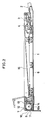
- Fig. 2 shows the interior construction of an automatic feeder for duplex (double-faced) documents which includes a drive transmission mechanism of the present invention.
- the feeder has the function of feeding the document onto a contact glass plate 1 of a copying machine and discharging the document, and the function of reversing the fed document and feeding the document onto the glass plate 1 again.
- the feeder has a feed assembly including a document tray 2, a feed roller 3, a pair of register rollers 4, etc.
- a conveyor belt 6 is provided above the glass plate 1. Disposed downstream from the belt is a mechanism 7 for reversing the document.
- the document reversing mechanism 7 comprises a guide member 9 and a reversing roller 10 having transport rollers 11, 12 in pressing contact with the roller 10.
- a switch guide plate 13 is disposed downstream from the roller 12.
- the switch guide plate 13 is shiftable between a first position as illustrated and a second position to which the plate 13 is slightly rotated counterclockwise in Fig. 2 from the first position.
- the switch guide plate 13 forms with the reversing roller 10 a return passage 14 through which the document is returned onto the glass plate 1.
- the plate 13 When in the second position, the plate 13 provides a document discharge passage for guiding the document to a discharge tray 15.
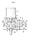
- the drive transmission mechanism (speed reduction mechanism) of the present invention is installed in the feeder for driving the shaft (driven shaft) 10a of the reversing roller 10.
- the drawing shows upright inside plates 20, 20′ provided in the feeder, and a motor 21 fixed to the inside plate 20 and having a drive shaft 21a projecting toward the inside plate 20′.
- An intermediate shaft 22 is fixed at its one end to the inside plate 20′.
- the shaft 10a of the reversing roller 10 is positioned in alignment with the drive shaft 21a and rotatably supported by a bearing 23 on the inside plate 20′.
- a drive gear 24 having a pitch circle of small diameter is fixed to the drive shaft 21a with a screw 25.
- a driven gear 26 having a pitch circle of large diameter is mounted on the roller shaft 10a and held to the shaft 10a against rotation. More specifically, a pin 10b extends through the shaft 10a, with opposite ends of the pin 10b projecting outward from the roller shaft periphery.
- a groove 26a formed in the driven gear 26 has the pin ends fitted therein.
- the drive gear 24 is coupled to the driven gear 26 by three intermediate gears 27 to 29 which are all identical in shape.
- Each of the intermediate gears 27 to 29 comprises a large gear (first transmission wheel) 27a (28a, 29a) having the same pitch circle as the driven gear 26, and a small gear (second transmission wheel) 27b (28b, 29b) integral with the large gear and having the same pitch circle as the drive gear 24.
- a stepped portion 27c (28c, 29c) is formed between the large gear 27a (28a, 29a) and the small gear 27b (28b, 29b).
- the gears mesh with one another in the following relationship.
- the mechanism is further characterized in that the intermediate gears 27, 29 are supported by the intermediate shaft 22 rotatably relative to each other, and that the intermediate gear 28 is supported by the roller shaft 10a rotatably relative to the shaft 10a and also to the driven gear 26.
- the intermediate gears 27, 29 as arranged in superposed layers (in series) are mounted on the intermediate shaft 22 rotatably relative to the shaft 22 and positioned in place by a retaining ring 30 axially of the shaft.
- the intermediate gear 28 mounted on the roller shaft 10a is positioned closer to the motor 21 than the driven gear 26 and held in this position axially thereof by the contact of one side face of its large gear 28a with the stepped portion 27c of the intermediate gear 27.
- the mechanism described above suppose the gear-to-gear speed transmission ratio is i (i ⁇ 1), and the angular velocity of the drive shaft 21a rotated by the operation of the motor 21 is ⁇ .
- the intermediate gear 27 in mesh with the drive gear 24 fixed to the drive shaft 21a then rotates at an angular velocity of ⁇ i.
- the intermediate gear 28 meshing with this intermediate gear 27 rotates at an angular velocity of ⁇ i2
- the intermediate gear 29 meshing with the gear 28 rotates at an angular velocity of ⁇ i3
- the driven gear 26 meshing with the gear 29 rotates with the roller shaft 10a at an angular velocity of ⁇ i4.
- the mechanism transmits the rotation of the drive shaft 21a to the roller shaft 10 at a reduction ratio of i4.
- the present mechanism requires five gears like the mechanism of Fig. 5, whereas these gears can be supported by three shafts, i.e., the drive shaft 21a, roller shaft 10a and single intermediate shaft 22. This serves to greatly reduce the space required to compact the body of the apparatus (i.e. the automatic document feeder), further making the mechanism simplified in construction and less costly.
- the intermediate gears 27 to 29 are shaped identically as in the present embodiment, a further cost reduction can be achieved. If the intermediate gear 28 is positioned in place by the stepped portion 27c of the intermediate gear 27 as stated above, a positioning member such as a retaining ring can be dispensed with. This leads to a further cost reduction and also makes it possible to position, for example, the drive shaft 21a very close to the roller shaft 10a end-to-end as illustrated for a greater reduction in the space needed.
- the gear arrangement shown in Fig. 1 requires that the pairs of meshing gears be definite in the axis-to-axis distance, more specifically in the sum of diameters of the pitch circles (the sum of tooth numbers in the case of equal modules).
- the advantages of the invention can be obtained insofar as at least two gears or the like are supported by the same shaft and made rotatable relative to each other.
- the intermediate gears 27, 29 may be supported by individual support shafts.
- the single roller shaft 10a supporting both the intermediate gear 28 and the driven gear 26 still serves to reduce the space by a corresponding amount.
- the intermediate gears 27, 29 need only to be rotatable relative to each other.
- the intermediate gear 27 may be fixed to the intermediate shaft 22 and made rotatable with the shaft 22, with the intermediate gear 29 mounted on the shaft 22 rotatably relative thereto.
- a plurality of gears may be mounted on the drive shaft 21a.
- the drive shaft 21a and the roller shaft 10a may be provided with the drive gear 24 and the driven gear 26 only, respectively, with at least two of the intermediate gears mounted on one shaft.
- the drive side and the driven side may be replaced by each other to use the arragement as a speed increasing mechanism.
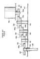
- This embodiment is characterized in that it comprises four intermediate gears, i.e., the above intermediate gears 27 to 29, and another intermediate gear 31 shaped identically with these gears and having a large gear 31a, a stepped portion 31c and a small gear 31b, all the gears being supported by only two shafts, i.e., the drive shaft 21a and the roller shaft 10a.
- the drive shaft 21a has mounted thereon the drive gear 24, intermediate gear 28 and intermediate gear 31 as arranged from the motor (21) side toward the inside plate 20′.
- the roller shaft 10a carries the driven gear 26, intermediate gear 29 and intermediate gear 27 as arranged from the reversing roller (10) side toward the inside plate 20. All the gears other than the drive gear 24 and the driven gear 26 are rotatable relative to the shaft concerned.
- the gears on the roller shaft 10a are positioned in place by a retaining ring 30.
- the gears on the drive shaft 21a are positioned in place by the contact of the stepped portion 31c of the intermediate gear 31 at the shaft end with one side face of toothed portion of the driven gear 26.
- all the gears can be supported by only two shafts, i.e., the drive shaft and the driven shaft. This results in a great reduction in the space required.
- drive shaft and "driven shaft” as used herein have relative meanings; the “drive shaft” need not always be connected directly to the drive source, nor is it always required that the “driven shaft” be connected directly to the member to be driven. In other words, these shafts may be connected to the drive source or driven member by another drive transmission means.
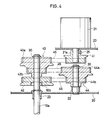
- FIG. 4 shows an arrangement wherein toothed pulleys and timing belts are used in place of the above gears.
- a drive pulley 41 is fixed to the drive shaft 21a of the motor 21 with a screw 25.
- a driven pulley 42 is fixed to the roller shaft 10a against rotation.
- An intermediate pulley 43 is rotatably mounted on the roller shaft 10a and positioned adjacent to the driven pulley 42.
- An intermediate shaft 22 fixed to the inside plate 20′ has mounted thereon an intermediate pulley 44 rotatably relative to the shaft 22.
- Each of the intermediate pulleys 43, 44 has a large pulley (first transmission wheel) 43a (44a) and a small pulley (second transmission wheel) 43b (44b) and is positioned in place by a retaining ring 30 axially of the shaft.
- the pulleys are coupled to one another by timing belts 45 in the following relationship.
- the torque of the motor 21 can also be transmitted to the roller shaft 10a via the drive pulley 41, intermediate pulleys 43, 44 and driven pulley 42 upon a great speed reduction.
- the intermediate pulley 43 and the driven pulley 42 supported by the same shaft (roller shaft 10a), the space required can be diminished.
- the present invention can be embodied with use of drive transmitting wheels of any type which include not only gears or toothed pulleys but also frictional wheels or usual pulleys for use with belts.
Landscapes
- Engineering & Computer Science (AREA)
- General Engineering & Computer Science (AREA)
- Mechanical Engineering (AREA)
- Gear Transmission (AREA)
- Devices For Conveying Motion By Means Of Endless Flexible Members (AREA)
Applications Claiming Priority (2)
| Application Number | Priority Date | Filing Date | Title |
|---|---|---|---|
| JP63301931A JPH0792120B2 (ja) | 1988-11-28 | 1988-11-28 | 駆動伝達機構 |
| JP301931/88 | 1988-11-28 |
Publications (3)
| Publication Number | Publication Date |
|---|---|
| EP0371690A2 true EP0371690A2 (fr) | 1990-06-06 |
| EP0371690A3 EP0371690A3 (en) | 1990-08-08 |
| EP0371690B1 EP0371690B1 (fr) | 1994-06-08 |
Family
ID=17902830
Family Applications (1)
| Application Number | Title | Priority Date | Filing Date |
|---|---|---|---|
| EP89312135A Expired - Lifetime EP0371690B1 (fr) | 1988-11-28 | 1989-11-22 | Mécanisme de transmission |
Country Status (5)
| Country | Link |
|---|---|
| US (1) | US5038629A (fr) |
| EP (1) | EP0371690B1 (fr) |
| JP (1) | JPH0792120B2 (fr) |
| KR (1) | KR930000493B1 (fr) |
| DE (1) | DE68915960T2 (fr) |
Cited By (3)
| Publication number | Priority date | Publication date | Assignee | Title |
|---|---|---|---|---|
| WO2001004512A1 (fr) | 1999-07-08 | 2001-01-18 | Maxon Motor Gmbh | Reducteur a plusieurs etages de pignons cylindriques |
| WO2007125373A1 (fr) * | 2006-04-28 | 2007-11-08 | Panagiotis Zaraphonitis | Mécanisme par transmission de distribution oscillante et moteur torique hermétique en tant qu'application de ce mécanisme |
| WO2017013266A1 (fr) * | 2015-07-23 | 2017-01-26 | Mmt Sa | Motoreducteur compact |
Families Citing this family (12)
| Publication number | Priority date | Publication date | Assignee | Title |
|---|---|---|---|---|
| US5413265A (en) * | 1990-07-07 | 1995-05-09 | Agfa-Gevaert A.G. | Arrangement for transporting web-shaped materials to be scanned or exposed |
| JP2592692Y2 (ja) * | 1991-01-23 | 1999-03-24 | 株式会社妙徳 | 各種自動機械の送り等制御装置 |
| KR100479712B1 (ko) * | 2002-01-03 | 2005-03-30 | 코리아케미칼 주식회사 | 내스크래취성을 이용한 금은박 열전사필름 및 그 제조방법 |
| US6857338B2 (en) | 2002-08-19 | 2005-02-22 | Molon Motor & Coil Corp. | High torque resistant and strong screwless plastic gear box |
| JP4879579B2 (ja) * | 2005-12-22 | 2012-02-22 | 本田技研工業株式会社 | 車両用パワーユニット |
| RU2362923C1 (ru) * | 2008-04-07 | 2009-07-27 | Государственное образовательное учреждение высшего профессионального образования Московский авиационный институт (государственный технический университет) (МАИ) | Зубчатый цилиндрический редуктор |
| US9163706B2 (en) * | 2012-08-29 | 2015-10-20 | Greg SEBLANTE, SR. | Sprocket box for increasing the gas mileage of a vehicle with an automatic transmission |
| US9377097B2 (en) * | 2014-02-21 | 2016-06-28 | Kuhn North America, Inc. | Cartridge drive |
| DE102014015318A1 (de) * | 2014-10-17 | 2016-04-21 | Drive & Innovation Gmbh & Co. Kg | Getriebeanordnung für einen an einen Rahmen eines mittels Tretkurbel angetriebenen Fahrzeugs anbaubaren Hilfsantrieb |
| KR102396608B1 (ko) * | 2016-03-15 | 2022-05-12 | 나이키 이노베이트 씨.브이. | 신발류용 모터 작동형 인장 시스템을 위한 변속 장치 |
| JP2018123884A (ja) * | 2017-01-31 | 2018-08-09 | 山田 秀雄 | プーリー群および動力伝達機構 |
| CN107707073B (zh) * | 2017-09-28 | 2023-07-14 | 深圳市优必选科技有限公司 | 一种无刷舵机 |
Family Cites Families (15)
| Publication number | Priority date | Publication date | Assignee | Title |
|---|---|---|---|---|
| NL53730C (fr) * | 1900-01-01 | |||
| US374146A (en) * | 1887-11-29 | Hekry essex | ||
| US654933A (en) * | 1900-05-03 | 1900-07-31 | Alva Appelgate | Governor for stacker-blowers. |
| US760218A (en) * | 1903-12-21 | 1904-05-17 | Friedrich Wilhelm Alt | Driving-gear for boats, &c. |
| US1502456A (en) * | 1923-01-15 | 1924-07-22 | Palmer Bee Co | Reduction gearing |
| US1585361A (en) * | 1924-01-28 | 1926-05-18 | Palmer Bee Co | Reduction gearing |
| US2908180A (en) * | 1956-05-04 | 1959-10-13 | American Nat Bank And Trust Co | Gear mechanism |
| US2831364A (en) * | 1956-07-17 | 1958-04-22 | Cons Electrodynamics Corp | Transmission construction |
| FR1448923A (fr) * | 1965-06-28 | 1966-08-12 | Riam Franco Suisse Sa | Nouvelle transmission |
| US3813956A (en) * | 1973-03-14 | 1974-06-04 | Smithkline Corp | Speed changer |
| US4478101A (en) * | 1980-07-31 | 1984-10-23 | Rumsa Antanas J | Mechanical transmission apparatus |
| JPS5874673U (ja) * | 1981-11-14 | 1983-05-20 | 松下電工株式会社 | 計量用羽根車の減速装置 |
| JPS58196454U (ja) * | 1982-06-24 | 1983-12-27 | オムロン株式会社 | 歯車機構 |
| JPS59112054U (ja) * | 1983-01-19 | 1984-07-28 | 松下電器産業株式会社 | 小型減速歯車装置 |
| US4487067A (en) * | 1983-08-05 | 1984-12-11 | The United States Of America As Represented By The Secretary Of The Army | High speed spin test device |
-
1988
- 1988-11-28 JP JP63301931A patent/JPH0792120B2/ja not_active Expired - Fee Related
-
1989
- 1989-11-20 KR KR1019890016804A patent/KR930000493B1/ko not_active Expired - Fee Related
- 1989-11-20 US US07/439,079 patent/US5038629A/en not_active Expired - Lifetime
- 1989-11-22 EP EP89312135A patent/EP0371690B1/fr not_active Expired - Lifetime
- 1989-11-22 DE DE68915960T patent/DE68915960T2/de not_active Expired - Fee Related
Cited By (9)
| Publication number | Priority date | Publication date | Assignee | Title |
|---|---|---|---|---|
| WO2001004512A1 (fr) | 1999-07-08 | 2001-01-18 | Maxon Motor Gmbh | Reducteur a plusieurs etages de pignons cylindriques |
| US6601467B1 (en) | 1999-07-08 | 2003-08-05 | Maxon Motor Gmbh | Multi-stage spur gear transmission |
| WO2007125373A1 (fr) * | 2006-04-28 | 2007-11-08 | Panagiotis Zaraphonitis | Mécanisme par transmission de distribution oscillante et moteur torique hermétique en tant qu'application de ce mécanisme |
| GR20060100255A (el) * | 2006-04-28 | 2007-11-15 | Παναγιωτης Βασιλειου Ζαραφωνιτης | Μηχανισμος επιμεριστικης ταλαντωτικης μεταδοσεως και τοροειδης ερμητικη μηχανη ως εφαρμογη αυτου |
| WO2017013266A1 (fr) * | 2015-07-23 | 2017-01-26 | Mmt Sa | Motoreducteur compact |
| FR3039337A1 (fr) * | 2015-07-23 | 2017-01-27 | Mmt Sa | Motoreducteur compact |
| KR20180033253A (ko) * | 2015-07-23 | 2018-04-02 | 엠엠티 에스아 | 콤팩트한 모터 감속기 |
| CN107925278A (zh) * | 2015-07-23 | 2018-04-17 | Mmt有限公司 | 紧凑型马达减速器 |
| CN115173625A (zh) * | 2015-07-23 | 2022-10-11 | Mmt有限公司 | 紧凑型马达减速器 |
Also Published As
| Publication number | Publication date |
|---|---|
| KR930000493B1 (ko) | 1993-01-21 |
| DE68915960T2 (de) | 1995-01-05 |
| EP0371690A3 (en) | 1990-08-08 |
| JPH02146356A (ja) | 1990-06-05 |
| KR900008741A (ko) | 1990-06-03 |
| DE68915960D1 (de) | 1994-07-14 |
| EP0371690B1 (fr) | 1994-06-08 |
| JPH0792120B2 (ja) | 1995-10-09 |
| US5038629A (en) | 1991-08-13 |
Similar Documents
| Publication | Publication Date | Title |
|---|---|---|
| EP0371690A2 (fr) | Mécanisme de transmission | |
| US4802373A (en) | Manual transmission with one primary shaft and two secondary shafts | |
| US5393044A (en) | Paper feeder | |
| EP0882189B1 (fr) | Anneau de transfert et dispositif d'engrenage pour transmission a changement de vitesses continu et a glissement limite | |
| US4785688A (en) | Torque limiter for paper feeding device of office machine and the like | |
| EP0600433A1 (fr) | Appareil de mouvement rectiligne | |
| EP0927316B1 (fr) | Differentiel d'entrainement par courroie | |
| US3989176A (en) | Web transporting system | |
| US5564309A (en) | Rectilinear motion apparatus | |
| US4379414A (en) | High ratio speed reducer | |
| US5036716A (en) | Infinitely variable transmission | |
| KR20220013670A (ko) | 파동기어를 이용한 감속장치 | |
| JPH0592804A (ja) | 基板搬送装置 | |
| JPS63137871A (ja) | プリンタの紙送り装置 | |
| AU724967C (en) | Belt drive differential | |
| EP0045190A2 (fr) | Dispositif de transmission de puissance | |
| JPH08101549A (ja) | 駆動力伝達装置及び画像形成装置 | |
| JPS6123967Y2 (fr) | ||
| EP0736701A1 (fr) | Combinaison d'un variateur à disques épicycloidale et d'un réducteur épicycloidale | |
| JP2547809B2 (ja) | 自動張力調整機構を有するベルト伝導装置 | |
| JPH039151A (ja) | 自動張力調整機構を有するベルト伝動装置 | |
| KR100412502B1 (ko) | 프린터의 용지 이송장치 | |
| KR0137591Y1 (ko) | 금전 등록기의 종이 이송장치 | |
| JPS6483973A (en) | Geared transmission device | |
| SU1015164A1 (ru) | Вариатор Овчинникова |
Legal Events
| Date | Code | Title | Description |
|---|---|---|---|
| PUAI | Public reference made under article 153(3) epc to a published international application that has entered the european phase |
Free format text: ORIGINAL CODE: 0009012 |
|
| AK | Designated contracting states |
Kind code of ref document: A2 Designated state(s): DE FR GB NL |
|
| PUAL | Search report despatched |
Free format text: ORIGINAL CODE: 0009013 |
|
| AK | Designated contracting states |
Kind code of ref document: A3 Designated state(s): DE FR GB NL |
|
| 17P | Request for examination filed |
Effective date: 19901116 |
|
| 17Q | First examination report despatched |
Effective date: 19920311 |
|
| GRAA | (expected) grant |
Free format text: ORIGINAL CODE: 0009210 |
|
| AK | Designated contracting states |
Kind code of ref document: B1 Designated state(s): DE FR GB NL |
|
| REF | Corresponds to: |
Ref document number: 68915960 Country of ref document: DE Date of ref document: 19940714 |
|
| ET | Fr: translation filed | ||
| PLBE | No opposition filed within time limit |
Free format text: ORIGINAL CODE: 0009261 |
|
| STAA | Information on the status of an ep patent application or granted ep patent |
Free format text: STATUS: NO OPPOSITION FILED WITHIN TIME LIMIT |
|
| 26N | No opposition filed | ||
| PGFP | Annual fee paid to national office [announced via postgrant information from national office to epo] |
Ref country code: FR Payment date: 19961111 Year of fee payment: 8 |
|
| PGFP | Annual fee paid to national office [announced via postgrant information from national office to epo] |
Ref country code: GB Payment date: 19961113 Year of fee payment: 8 |
|
| PGFP | Annual fee paid to national office [announced via postgrant information from national office to epo] |
Ref country code: NL Payment date: 19961128 Year of fee payment: 8 |
|
| PGFP | Annual fee paid to national office [announced via postgrant information from national office to epo] |
Ref country code: DE Payment date: 19961202 Year of fee payment: 8 |
|
| PG25 | Lapsed in a contracting state [announced via postgrant information from national office to epo] |
Ref country code: GB Free format text: LAPSE BECAUSE OF NON-PAYMENT OF DUE FEES Effective date: 19971122 |
|
| PG25 | Lapsed in a contracting state [announced via postgrant information from national office to epo] |
Ref country code: FR Free format text: THE PATENT HAS BEEN ANNULLED BY A DECISION OF A NATIONAL AUTHORITY Effective date: 19971130 |
|
| PG25 | Lapsed in a contracting state [announced via postgrant information from national office to epo] |
Ref country code: NL Free format text: LAPSE BECAUSE OF NON-PAYMENT OF DUE FEES Effective date: 19980601 |
|
| GBPC | Gb: european patent ceased through non-payment of renewal fee |
Effective date: 19971122 |
|
| PG25 | Lapsed in a contracting state [announced via postgrant information from national office to epo] |
Ref country code: DE Free format text: LAPSE BECAUSE OF NON-PAYMENT OF DUE FEES Effective date: 19980801 |
|
| NLV4 | Nl: lapsed or anulled due to non-payment of the annual fee |
Effective date: 19980601 |
|
| REG | Reference to a national code |
Ref country code: FR Ref legal event code: ST |