EP0371709A1 - Dispositif de suspension pour véhicule - Google Patents
Dispositif de suspension pour véhicule Download PDFInfo
- Publication number
- EP0371709A1 EP0371709A1 EP89312228A EP89312228A EP0371709A1 EP 0371709 A1 EP0371709 A1 EP 0371709A1 EP 89312228 A EP89312228 A EP 89312228A EP 89312228 A EP89312228 A EP 89312228A EP 0371709 A1 EP0371709 A1 EP 0371709A1
- Authority
- EP
- European Patent Office
- Prior art keywords
- piston
- fluid
- suspension device
- vehicle suspension
- chamber
- Prior art date
- Legal status (The legal status is an assumption and is not a legal conclusion. Google has not performed a legal analysis and makes no representation as to the accuracy of the status listed.)
- Granted
Links
- 239000000725 suspension Substances 0.000 title claims abstract description 46
- 239000012530 fluid Substances 0.000 claims abstract description 68
- 230000003068 static effect Effects 0.000 claims description 3
- 238000004364 calculation method Methods 0.000 description 3
- 238000013016 damping Methods 0.000 description 2
- 230000000694 effects Effects 0.000 description 1
- 238000005265 energy consumption Methods 0.000 description 1
- 239000010720 hydraulic oil Substances 0.000 description 1
- 239000003921 oil Substances 0.000 description 1
- 230000000630 rising effect Effects 0.000 description 1
- 238000004088 simulation Methods 0.000 description 1
Images


Classifications
-
- B—PERFORMING OPERATIONS; TRANSPORTING
- B60—VEHICLES IN GENERAL
- B60G—VEHICLE SUSPENSION ARRANGEMENTS
- B60G17/00—Resilient suspensions having means for adjusting the spring or vibration-damper characteristics, for regulating the distance between a supporting surface and a sprung part of vehicle or for locking suspension during use to meet varying vehicular or surface conditions, e.g. due to speed or load
- B60G17/06—Characteristics of dampers, e.g. mechanical dampers
- B60G17/08—Characteristics of fluid dampers
-
- B—PERFORMING OPERATIONS; TRANSPORTING
- B60—VEHICLES IN GENERAL
- B60G—VEHICLE SUSPENSION ARRANGEMENTS
- B60G17/00—Resilient suspensions having means for adjusting the spring or vibration-damper characteristics, for regulating the distance between a supporting surface and a sprung part of vehicle or for locking suspension during use to meet varying vehicular or surface conditions, e.g. due to speed or load
- B60G17/02—Spring characteristics, e.g. mechanical springs and mechanical adjusting means
- B60G17/04—Spring characteristics, e.g. mechanical springs and mechanical adjusting means fluid spring characteristics
-
- B—PERFORMING OPERATIONS; TRANSPORTING
- B60—VEHICLES IN GENERAL
- B60G—VEHICLE SUSPENSION ARRANGEMENTS
- B60G2202/00—Indexing codes relating to the type of spring, damper or actuator
- B60G2202/40—Type of actuator
- B60G2202/41—Fluid actuator
- B60G2202/413—Hydraulic actuator
-
- B—PERFORMING OPERATIONS; TRANSPORTING
- B60—VEHICLES IN GENERAL
- B60G—VEHICLE SUSPENSION ARRANGEMENTS
- B60G2202/00—Indexing codes relating to the type of spring, damper or actuator
- B60G2202/40—Type of actuator
- B60G2202/41—Fluid actuator
- B60G2202/414—Fluid actuator using electrohydraulic valves
-
- B—PERFORMING OPERATIONS; TRANSPORTING
- B60—VEHICLES IN GENERAL
- B60G—VEHICLE SUSPENSION ARRANGEMENTS
- B60G2600/00—Indexing codes relating to particular elements, systems or processes used on suspension systems or suspension control systems
- B60G2600/18—Automatic control means
- B60G2600/182—Active control means
Definitions
- This invention relates to a vehicle suspension device.
- the invention relates to a combined actuator and damper for a vehicle suspension system of the kind in which the actuator is positioned between the vehicle hub and the sprung mass of the vehicle and the position of the sprung mass relative to the hub is determined or assisted by the actuator.
- the actuator may be used in parallel with the normal vehicle road spring or in exceptional circumstances may completely replace the vehicle road spring.
- the prior art includes a strut in the form of a double acting piston and cylinder device where hydraulic fluid is fed to either side of the piston by a control valve and exhausted from the other side of the piston depending upon a desired relative movement between the vehicle hub and the sprung mass.
- a strut When included in a vehicle suspension control system including control means and a suitable hydraulic circuit, such a strut forms an essential element of what is known in the art as an "active suspension system".
- a vehicle suspension device comprising a piston and cylinder arrangement included in a fluid control circuit, a first surface of the piston acting in a first chamber of the cylinder being of smaller area than a second surface of the piston acting in a second chamber of the cylinder, wherein said first chamber is connected via fluid connection means to a source of pressurised fluid and said second chamber is selectively connectable via fluid connection means to one or more of a source of pressurised fluid, an accumulator of pressurised fluid and an exhaust for pressurised fluid.
- the vehicle suspension includes an actuator rod secured to the first surface of the piston, which actuator rod extends longitudinally along the first chamber through an aperture in a wall thereof externally of the cylinder to interconnect the piston and an object supported on the suspension device, thereby forming the reduced area of the first surface of the piston in comparison with the second surface thereof.
- piston and cylinder arrangement interconnects the sprung mass of a motor vehicle and a road wheel hub assembly thereof.
- a vehicle suspension system including a vehicle suspension device as hereinbefore defined.
- the vehicle suspension system includes transducers and/or sensors for detecting the operating characteristics of the vehicle suspension device and for detecting the static and dynamic characteristics of the vehicle, and further includes an on-board computer for processing the detected characteristics and operating the vehicle suspension device accordingly.
- the two unequal area sides of the piston are connectable to the system pressure and an accumulator and valve means is used to operate under command to achieve the desired result.
- the larger area of the piston is the upper side in use and the system pressure is fed to the lower side of the piston.
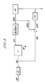
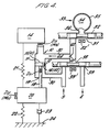
- a vehicle suspension device formed as a piston and cylinder arrangement 10 comprising a cylinder 11 and a double-acting piston 12.
- the cylinder 11 is aligned generally vertically and is connected at its upper end via an isolator and a load cell i and D3 to the sprung mass 14 of a road vehicle.
- the piston 12 has two working surfaces 15 and 16 against which fluid pressure may act and the upper surface 15 is of larger area than the lower surface 16. This is due to the presence of a downwardly-extending actuator rod 18 rigidly secured on the lower surface 16 of piston 12 and extending externally of cylinder 11 via an aperture 19. The area of surface 16 is half that of surface 15.
- Actuator rod 18 is rigidly secured to road wheel hub assembly 20 and suspension device 10 therefore acts as a strut interconnecting sprung mass 14 and hub assembly 20.
- a normal road spring 21 is also shown schematically in Figure 1 interconnecting the sprung mass 14 and hub assembly 20, in parallel with suspension device 10.
- the tyre of the road wheel of hub assembly 20 is shown in Figure 1 schematically as a parallel spring 22 and dashpot 23 representing the elastic and damping characteristics of the tyre.
- the tyre is supported on a road surface 24.
- the upper end of cylinder 11 is fluidly connected via suitable pipework 30 to a spool valve 31 having a spool 32.
- Spool valve 31 is arranged to act as an on-off valve, selectively permitting fluid interconnection of the upper side of cylinder 11 and a compressible accumulator 33 for pressurised fluid.
- the accumulator 33 includes a deformable, sealed member 34 such as a gas bag enclosed within a rigid outer container 35.
- pressurised fluid such as hydraulic oil enters the accumulator 33 via spool valve 31, the deformable member 34 deforms within the container 35 until a pressure equilibrium exists between the pressurised fluid and the interior of the deformable member.
- the pressurised fluid occupies the space 36, which is enlarged by deformation of the deformable member 34.
- the accumulator 33 thus stores the pressure energy in the fluid until some time when a pressure lower than that of the pressurised fluid in space 36 exists on the opposite side of spool valve 31 to that of accumulator 33 and the valve 33 is opened.
- the excess pressure in the deformable member then drives the fluid stored in space 36 back through valve 31, the deformable member expanding to occupy a larger volume within rigid container 35 as this takes place.
- the lower end of cylinder 11 is permanently connected via suitable pipework 30 to a source of pressurised fluid indicated by the arrow S in Figure 1.
- the suspension device operates using hydrauylic oil, so the source of pressurised fluid is a pump P, shown in Figure 2.
- the source of pressurised fluid would be a compressor.
- the source S of pressurised fluid is selectively connectable, via a three-port two-way spool valve 38 having spool 39, to the upper side of cylinder 11 and the inlet of spool valve 31.
- the upper side 15 of cylinder 11 and, if required, accumulator 33, may also be selectively connected to an exhaust indicated by the arrow E in Figure 1. Since the fluid control circuit shown in Figure 1 is an hydraulic circuit, the exhaust E may be the input side of a suitable pressurising pump or a sump.
- the spool valves 31, 38 are shown closed in Figure 1 for clarity, but this does not necessarily represent an operative state of the system. However, Figure 1 does clearly show that the lower surface 16 of piston 12 is permanently connected to a supply of pressurised hydraulic fluid.
- Means for moving the spool valve 39 is schematically indicated at 39′ and may be a solenoid.
- valve spool 39 If the valve spool 39 is moved to the left in Figure 1, the upper surface 15 of piston 12 is also connected to the source of pressurised hydraulic fluid S while, due to the spool valve action, the exhaust port E remains closed. The net pressure force on piston 12 thus causes it to move downwardly with respect to the cylinder 11, because the area 15 is bigger than the area 16.
- valve spool 39 similarly opens the exhaust port E and disconnects the upper surface 15 of the piston from the supply S, resulting in a net upward pressure force acting on piston 12 and causing it to move upwardly within cylinder 11.
- the circuit provides a means of controlling the relative positions of the sprung mass 14 and the roadwheel hub 20, and when suitable transducers and detectors (referred as D1, D2, D3) are included to sense (or allow to be be calculated) the relative position of the piston 12, the roadwheel hub assembly 20 and the sprung mass 14, the device can operate under the command of an on-board computer C (shown in Figure 2) to provide a rapidly responsive system.
- the transducers and/or detectors send signals d1,d2,d3 to the computer which generates a demanded position of the piston 12 required to provide a required relative movement of the sprung mass and roadwheel hub assembly. Once it has calculated the demanded position of the piston 12 the computer sends a control signal c to means 39′ to control the position of the valve appropriately.
- a variety of dynamic situations may arise, including the case where the relative movement of the sprung mass 14 and the roadwheel hub assembly 20 tends to aid the movement of the piston 12 towards a demanded position calculated by the computer.
- a situation may arise, for example, when the roadwheel encounters a bump in the road surface 24 when the vehicle is travelling at speed.
- the piston 12 is required to rise within cylinder 11 in order to minimise the perturbation experienced by the sprung mass 14 of the vehicle.
- the relative movement of the roadwheel hub assembly 20 and the sprung mass 14 assists the movement of the piston 12 in attaining its demanded position.
- an accumulator 33 for pressurised fluid is provided, and this may be selectively connected to the upper side 15 of piston 12 via spool valve 31, which is arranged to act as an on-off valve for the connection between accumulator 33 and the upper side 15 of piston 12.
- any excess hydraulic energy in the hydraulic fluid on the upper side of piston 12 may be accumulated in accumulator 33 by valve spool 32 moving to the left under the command of the computer to open the connection between upper side 15 and space 36.
- Spool 32 moves to the right to close the connection and thus store the hydraulic energy when the computer detects that it is no longer required for the connection to be open. This may occur when, for example, the accumulator 33 is charged to capacity with hydraulic fluid, in which case any further excess fluid, and hence further excess hydraulic energy, may be exhausted via spool valve 38 and exhaust E.
- the stored hydraulic energy in the accumulator 33 may be used, on opening of spool valve 31 to interconnect space 36 and the upper side 15 of piston 12, to assist the downward movement of the piston 12.
- the upper 15 and lower 16 sides of the piston 12 may be hydraulically interconnected at will via spool valve 38 despite the fact that the areas of the respective piston sides are different, since the accumulator 33 may be used to store and supply hydraulic fluid as required during movement of the piston 12.
- a single pump P is shown supplying the devices at wheels 40 and 41 of the vehicle via valves 42 and 43 in the supply and exhaust fluid passageways which isolate the fluid connections to the devices at wheels 40 and 41 from each other. Separate pumps and passageways could of course be provided for each wheel.
- Each device at each wheel is shown with its own accumulator 33, but the devices could share accumulators, and even a single accumulator may be provided to which each of the devices is connected.
- the suspenson device of the invention can be made smaller and more rapidly responsive than previous devices. Further, the hydraulic control components such as the pump P interconnecting the supply S and exhaust E can be made more compact due to the reduced energy requirements.
- the unequal area actuator system of the invention exhibited comparable step response characteristics to both the standard active control system and a conventional equal area system.
- the effects of actuator friction were not included in the model, as well as any isolator damping or stiffness, all of which will contribute to errors in the calculation of internal pressure. Furthermore, for these simulations, system pressure variation was ignored.
- FIGS 3 and 4 illustrate an operational algorithm for one embodiment of the invention.
- a fluid velocity demand Vd for the piston and cylinder device 10 is calculated by the computer C. Signals are fed to the computer from the wheel hub, the piston, and the body of the vehicle to enable Vd to be calculated. For example, the force on the body supported by the device, the relativce positions of the sprung and unsprung masses Ms and Mu, and any other appropriate signals. The actual value of Vd will depend upon how the system is designed to respond to inputs and is not central to the present invention.
- the fluid velocity demand Vd is then combined with the area A1 above the piston to give a quantity demand Qd representing the demanded quantity of fluid which it is required should flow to the piston 12.
- the computer C also ascertains from d1, d2, d3, (or the relative pressures in passages 30 above and below the piston 12) whether the load between the sprung and unsprung masses is aiding movement of the piston in its desired direction.
- This test is represented as box T in Figure 3.
- a calculation is then made to compare the quantity of fluid demanded Qd with the maximum quantity which can flow from the accumulator via the spool valve 31. Obviously, the supply from the accumulator can never exceed this figure and so the demanded quantity must be compared with it to see if more fluid is needed and an additional required quantity Q2 is calculated.
- the quantity demanded Qd is also fed through the lower half of the algorithm and is compared with the Q2 demanded (which is the quantity through the second spool 31) and only if Q2 is not sufficient for the Q demanded is an additional quantity Q1 required from fluid flowing through the first valve spool 38. Both required flow signals Q1 and Q2 then pass through a flow adjustment calculation FA to compensate for such things as the relative flows when both valves are open etc.
Landscapes
- Engineering & Computer Science (AREA)
- Mechanical Engineering (AREA)
- Vehicle Body Suspensions (AREA)
Priority Applications (1)
| Application Number | Priority Date | Filing Date | Title |
|---|---|---|---|
| AT89312228T ATE91256T1 (de) | 1988-11-28 | 1989-11-24 | Fahrzeugaufhaengungsvorrichtung. |
Applications Claiming Priority (2)
| Application Number | Priority Date | Filing Date | Title |
|---|---|---|---|
| GB8827745 | 1988-11-28 | ||
| GB888827745A GB8827745D0 (en) | 1988-11-28 | 1988-11-28 | Vehicle suspension device |
Publications (2)
| Publication Number | Publication Date |
|---|---|
| EP0371709A1 true EP0371709A1 (fr) | 1990-06-06 |
| EP0371709B1 EP0371709B1 (fr) | 1993-07-07 |
Family
ID=10647584
Family Applications (1)
| Application Number | Title | Priority Date | Filing Date |
|---|---|---|---|
| EP89312228A Expired - Lifetime EP0371709B1 (fr) | 1988-11-28 | 1989-11-24 | Dispositif de suspension pour véhicule |
Country Status (9)
| Country | Link |
|---|---|
| US (1) | US5082308A (fr) |
| EP (1) | EP0371709B1 (fr) |
| JP (1) | JPH02179536A (fr) |
| KR (1) | KR900007638A (fr) |
| AT (1) | ATE91256T1 (fr) |
| CA (1) | CA2003636C (fr) |
| DE (1) | DE68907468T2 (fr) |
| ES (1) | ES2042009T3 (fr) |
| GB (1) | GB8827745D0 (fr) |
Cited By (12)
| Publication number | Priority date | Publication date | Assignee | Title |
|---|---|---|---|---|
| WO1991007290A1 (fr) * | 1989-11-15 | 1991-05-30 | Robert Bosch Gmbh | Suspension de vehicule |
| US5137299A (en) * | 1991-04-26 | 1992-08-11 | Trw Inc. | Active suspension system |
| US5145206A (en) * | 1991-03-07 | 1992-09-08 | Trw Inc. | Semi-active suspension system with energy saving actuator |
| EP0512358A1 (fr) * | 1991-05-06 | 1992-11-11 | FIAT AUTO S.p.A. | Système de réglage de la charge d'une barre stabilisatrice dans une suspension indépendante de véhicule automobile |
| WO1994018020A1 (fr) * | 1993-02-04 | 1994-08-18 | Lotus Cars Limited | Dispositif de suspension de vehicule |
| WO1996011815A1 (fr) * | 1994-10-12 | 1996-04-25 | Holt Laurence J | Dispositif de suspension |
| GB2310024B (en) * | 1996-02-06 | 2000-05-17 | Monroe Auto Equipment Co | active suspension system |
| GB2343932A (en) * | 1996-02-06 | 2000-05-24 | Monroe Auto Equipment Co | Active suspension system |
| EP1238834A3 (fr) * | 2001-03-10 | 2003-08-27 | Bayerische Motoren Werke Aktiengesellschaft | Système de suspension active d'un véhicule |
| WO2007020052A1 (fr) * | 2005-08-16 | 2007-02-22 | Trw Automotive Gmbh | Actionneur hydraulique, destine notamment a un systeme de stabilisation de chassis, et circuit hydraulique comportant un tel actionneur |
| EP1902874A1 (fr) | 2006-09-19 | 2008-03-26 | Ricardo Deutschland GmbH | Système de châssis actif |
| US8672337B2 (en) | 2008-08-12 | 2014-03-18 | Nederlandse Organisatie Voor Toegepast-Natuurwetenschappelijk Onderzoek Tno | Multi-point hydraulic suspension system for a land vehicle |
Families Citing this family (12)
| Publication number | Priority date | Publication date | Assignee | Title |
|---|---|---|---|---|
| DE4014466A1 (de) * | 1990-05-07 | 1991-11-14 | Bosch Gmbh Robert | Fahrzeugfederung |
| US5570286A (en) * | 1993-12-23 | 1996-10-29 | Lord Corporation | Regenerative system including an energy transformer which requires no external power source to drive same |
| US5486018A (en) * | 1994-08-05 | 1996-01-23 | Yamaha Hatsudoki Kabushiki Kaisha | Suspension system for four-wheeled vehicles |
| DE19821305A1 (de) * | 1998-05-13 | 1999-11-18 | Wabco Gmbh | Niveauregeleinrichtung |
| DE102009060999A1 (de) | 2009-06-24 | 2011-01-05 | German Gresser | Energieoptimiertes Elektrofahrzeug mit autarker Stromversorgung und Verfahren zur Stromerzeugung, bevorzugt aus kinetischer und Gravitationsenergie |
| US8534687B2 (en) | 2010-07-05 | 2013-09-17 | Fluid Ride Ltd. | Suspension strut for a vehicle |
| US8434771B2 (en) * | 2011-06-14 | 2013-05-07 | Honda Motor Co., Ltd. | Piston-type actuator and static fluid damper and vehicles including same |
| US9574582B2 (en) | 2012-04-23 | 2017-02-21 | Fluid Ride, Ltd. | Hydraulic pump system and method of operation |
| US8820064B2 (en) | 2012-10-25 | 2014-09-02 | Tenneco Automotive Operating Company Inc. | Recuperating passive and active suspension |
| EP3580075A4 (fr) * | 2017-02-12 | 2021-01-20 | Clearmotion, Inc. | Actionneur hydraulique à rapport de pression relative dépendant de la fréquence |
| US10358010B2 (en) | 2017-06-05 | 2019-07-23 | Tenneco Automotive Operating Company Inc. | Interlinked active suspension |
| CN113752775A (zh) * | 2021-11-08 | 2021-12-07 | 杭州非白三维科技有限公司 | 通过减震变软使新能源汽车通过障碍物的制动机构 |
Citations (3)
| Publication number | Priority date | Publication date | Assignee | Title |
|---|---|---|---|---|
| US3482855A (en) * | 1967-03-29 | 1969-12-09 | Rene Capgras | Hydropneumatic suspension |
| US3492013A (en) * | 1967-05-25 | 1970-01-27 | Westinghouse Electric Corp | Vehicle stabilizer system with power valve damping |
| FR2562843A1 (fr) * | 1984-04-14 | 1985-10-18 | Bosch Gmbh Robert | Dispositif de commande de la durete de la suspension d'un vehicule |
Family Cites Families (5)
| Publication number | Priority date | Publication date | Assignee | Title |
|---|---|---|---|---|
| JPS61105631A (ja) * | 1984-10-29 | 1986-05-23 | Dai Ichi Seiko Co Ltd | タツチエントリ付液晶表示装置 |
| JPS621611A (ja) * | 1985-06-27 | 1987-01-07 | Nissan Motor Co Ltd | 能動型サスペンシヨン制御装置 |
| JPS6341224A (ja) * | 1986-08-05 | 1988-02-22 | Mazda Motor Corp | 車両のサスペンシヨン装置 |
| DE3638574A1 (de) * | 1986-11-12 | 1988-05-26 | Rexroth Mannesmann Gmbh | Anordnung zur drucksteuerung eines daempfungszylinders fuer die abfederung von fahrzeugen |
| US4804111A (en) * | 1987-02-20 | 1989-02-14 | Acrison, Inc. | Mechanism for metering solid materials which flow in a manner similar to liquids |
-
1988
- 1988-11-28 GB GB888827745A patent/GB8827745D0/en active Pending
-
1989
- 1989-11-22 CA CA002003636A patent/CA2003636C/fr not_active Expired - Fee Related
- 1989-11-24 EP EP89312228A patent/EP0371709B1/fr not_active Expired - Lifetime
- 1989-11-24 DE DE89312228T patent/DE68907468T2/de not_active Expired - Fee Related
- 1989-11-24 ES ES198989312228T patent/ES2042009T3/es not_active Expired - Lifetime
- 1989-11-24 AT AT89312228T patent/ATE91256T1/de not_active IP Right Cessation
- 1989-11-27 US US07/441,828 patent/US5082308A/en not_active Expired - Fee Related
- 1989-11-28 KR KR1019890017280A patent/KR900007638A/ko not_active Ceased
- 1989-11-28 JP JP1308835A patent/JPH02179536A/ja active Pending
Patent Citations (3)
| Publication number | Priority date | Publication date | Assignee | Title |
|---|---|---|---|---|
| US3482855A (en) * | 1967-03-29 | 1969-12-09 | Rene Capgras | Hydropneumatic suspension |
| US3492013A (en) * | 1967-05-25 | 1970-01-27 | Westinghouse Electric Corp | Vehicle stabilizer system with power valve damping |
| FR2562843A1 (fr) * | 1984-04-14 | 1985-10-18 | Bosch Gmbh Robert | Dispositif de commande de la durete de la suspension d'un vehicule |
Cited By (15)
| Publication number | Priority date | Publication date | Assignee | Title |
|---|---|---|---|---|
| WO1991007290A1 (fr) * | 1989-11-15 | 1991-05-30 | Robert Bosch Gmbh | Suspension de vehicule |
| US5145206A (en) * | 1991-03-07 | 1992-09-08 | Trw Inc. | Semi-active suspension system with energy saving actuator |
| US5137299A (en) * | 1991-04-26 | 1992-08-11 | Trw Inc. | Active suspension system |
| EP0512358A1 (fr) * | 1991-05-06 | 1992-11-11 | FIAT AUTO S.p.A. | Système de réglage de la charge d'une barre stabilisatrice dans une suspension indépendante de véhicule automobile |
| US5678846A (en) * | 1993-02-04 | 1997-10-21 | Lotus Cars Limited | Vehicle suspension device |
| WO1994018020A1 (fr) * | 1993-02-04 | 1994-08-18 | Lotus Cars Limited | Dispositif de suspension de vehicule |
| WO1996011815A1 (fr) * | 1994-10-12 | 1996-04-25 | Holt Laurence J | Dispositif de suspension |
| US5839742A (en) * | 1994-10-12 | 1998-11-24 | Holt; Laurence J. | Cam operated vehicle suspension system |
| GB2310024B (en) * | 1996-02-06 | 2000-05-17 | Monroe Auto Equipment Co | active suspension system |
| GB2343932A (en) * | 1996-02-06 | 2000-05-24 | Monroe Auto Equipment Co | Active suspension system |
| GB2343932B (en) * | 1996-02-06 | 2000-08-02 | Monroe Auto Equipment Co | Active suspension system |
| EP1238834A3 (fr) * | 2001-03-10 | 2003-08-27 | Bayerische Motoren Werke Aktiengesellschaft | Système de suspension active d'un véhicule |
| WO2007020052A1 (fr) * | 2005-08-16 | 2007-02-22 | Trw Automotive Gmbh | Actionneur hydraulique, destine notamment a un systeme de stabilisation de chassis, et circuit hydraulique comportant un tel actionneur |
| EP1902874A1 (fr) | 2006-09-19 | 2008-03-26 | Ricardo Deutschland GmbH | Système de châssis actif |
| US8672337B2 (en) | 2008-08-12 | 2014-03-18 | Nederlandse Organisatie Voor Toegepast-Natuurwetenschappelijk Onderzoek Tno | Multi-point hydraulic suspension system for a land vehicle |
Also Published As
| Publication number | Publication date |
|---|---|
| GB8827745D0 (en) | 1988-12-29 |
| DE68907468D1 (de) | 1993-08-12 |
| CA2003636C (fr) | 1994-08-02 |
| JPH02179536A (ja) | 1990-07-12 |
| KR900007638A (ko) | 1990-06-01 |
| ES2042009T3 (es) | 1993-12-01 |
| US5082308A (en) | 1992-01-21 |
| DE68907468T2 (de) | 1993-10-21 |
| CA2003636A1 (fr) | 1990-05-28 |
| EP0371709B1 (fr) | 1993-07-07 |
| ATE91256T1 (de) | 1993-07-15 |
Similar Documents
| Publication | Publication Date | Title |
|---|---|---|
| EP0371709B1 (fr) | Dispositif de suspension pour véhicule | |
| US6519517B1 (en) | Active ride control for a vehicle suspension system | |
| US4743000A (en) | Method and apparatus for controlling spring stiffness, in particular in vehicles | |
| US7360777B2 (en) | Vehicle suspension system | |
| JP5031563B2 (ja) | 油圧式車両サスペンションシステム | |
| US5642282A (en) | Apparatus for controlling attitude of a road vehicle cab | |
| US5098119A (en) | Semi-active suspension system with energy saving | |
| CN104401198B (zh) | 液压式车辆主动悬架系统 | |
| US5087072A (en) | Attitude change suppressive control system for active suspension system for automotive vehicle | |
| JP2000264034A (ja) | アクティブサスペンションの制御装置 | |
| JP2003080918A (ja) | 車両懸架システム | |
| CN107407294B (zh) | 用于车辆的液压机械悬架 | |
| US12522039B2 (en) | Suspension system with proportional pressure accumulator | |
| JPH0295910A (ja) | 自動車用アクティブサスペンションの制御装置 | |
| Darling et al. | A theoretical investigation of a prototype active roll control system | |
| JP6361414B2 (ja) | 車両のサスペンション装置 | |
| Rosam et al. | Development and simulation of a novel roll control system for the interconnected hydragas® suspension | |
| EP1189774B1 (fr) | Systeme de reglage actif pour suspension de vehicule | |
| JPH06510102A (ja) | 緩衝ユニット | |
| JPH0314715A (ja) | 車輌懸架系 | |
| US5080391A (en) | Vehicular height regulation system for automotive vehicle with active fluid pressure within predetermined variation range | |
| CN118722109A (zh) | 一种液压被动、自动主动悬架 | |
| JPH04262909A (ja) | 走行機構のばねシリンダを制御するためのシステム | |
| CN115972840A (zh) | 一种液压互联悬架系统及其控制方法 | |
| WO2000029825A1 (fr) | Ensemble chargement pourvu d'un actionneur souple |
Legal Events
| Date | Code | Title | Description |
|---|---|---|---|
| PUAI | Public reference made under article 153(3) epc to a published international application that has entered the european phase |
Free format text: ORIGINAL CODE: 0009012 |
|
| 17P | Request for examination filed |
Effective date: 19891202 |
|
| AK | Designated contracting states |
Kind code of ref document: A1 Designated state(s): AT BE DE ES FR GB IT LU NL SE |
|
| 17Q | First examination report despatched |
Effective date: 19920724 |
|
| GRAA | (expected) grant |
Free format text: ORIGINAL CODE: 0009210 |
|
| AK | Designated contracting states |
Kind code of ref document: B1 Designated state(s): AT BE DE ES FR GB IT LU NL SE |
|
| PG25 | Lapsed in a contracting state [announced via postgrant information from national office to epo] |
Ref country code: NL Effective date: 19930707 Ref country code: AT Effective date: 19930707 |
|
| REF | Corresponds to: |
Ref document number: 91256 Country of ref document: AT Date of ref document: 19930715 Kind code of ref document: T |
|
| REF | Corresponds to: |
Ref document number: 68907468 Country of ref document: DE Date of ref document: 19930812 |
|
| ET | Fr: translation filed | ||
| ITF | It: translation for a ep patent filed | ||
| PG25 | Lapsed in a contracting state [announced via postgrant information from national office to epo] |
Ref country code: LU Free format text: LAPSE BECAUSE OF NON-PAYMENT OF DUE FEES Effective date: 19931130 |
|
| REG | Reference to a national code |
Ref country code: ES Ref legal event code: FG2A Ref document number: 2042009 Country of ref document: ES Kind code of ref document: T3 |
|
| NLV1 | Nl: lapsed or annulled due to failure to fulfill the requirements of art. 29p and 29m of the patents act | ||
| REG | Reference to a national code |
Ref country code: GB Ref legal event code: 732E |
|
| RAP2 | Party data changed (patent owner data changed or rights of a patent transferred) |
Owner name: GROUP LOTUS LIMITED |
|
| PLBE | No opposition filed within time limit |
Free format text: ORIGINAL CODE: 0009261 |
|
| STAA | Information on the status of an ep patent application or granted ep patent |
Free format text: STATUS: NO OPPOSITION FILED WITHIN TIME LIMIT |
|
| 26N | No opposition filed | ||
| EAL | Se: european patent in force in sweden |
Ref document number: 89312228.3 |
|
| PGFP | Annual fee paid to national office [announced via postgrant information from national office to epo] |
Ref country code: FR Payment date: 19961112 Year of fee payment: 8 |
|
| PGFP | Annual fee paid to national office [announced via postgrant information from national office to epo] |
Ref country code: GB Payment date: 19961115 Year of fee payment: 8 |
|
| PGFP | Annual fee paid to national office [announced via postgrant information from national office to epo] |
Ref country code: SE Payment date: 19961118 Year of fee payment: 8 |
|
| PGFP | Annual fee paid to national office [announced via postgrant information from national office to epo] |
Ref country code: ES Payment date: 19961121 Year of fee payment: 8 |
|
| PGFP | Annual fee paid to national office [announced via postgrant information from national office to epo] |
Ref country code: BE Payment date: 19961128 Year of fee payment: 8 |
|
| PGFP | Annual fee paid to national office [announced via postgrant information from national office to epo] |
Ref country code: DE Payment date: 19970123 Year of fee payment: 8 |
|
| PG25 | Lapsed in a contracting state [announced via postgrant information from national office to epo] |
Ref country code: GB Free format text: LAPSE BECAUSE OF NON-PAYMENT OF DUE FEES Effective date: 19971124 |
|
| PG25 | Lapsed in a contracting state [announced via postgrant information from national office to epo] |
Ref country code: SE Free format text: LAPSE BECAUSE OF NON-PAYMENT OF DUE FEES Effective date: 19971125 Ref country code: ES Free format text: LAPSE BECAUSE OF EXPIRATION OF PROTECTION Effective date: 19971125 |
|
| PG25 | Lapsed in a contracting state [announced via postgrant information from national office to epo] |
Ref country code: FR Free format text: THE PATENT HAS BEEN ANNULLED BY A DECISION OF A NATIONAL AUTHORITY Effective date: 19971130 Ref country code: BE Free format text: LAPSE BECAUSE OF NON-PAYMENT OF DUE FEES Effective date: 19971130 |
|
| BERE | Be: lapsed |
Owner name: GROUP LOTUS P.L.C. Effective date: 19971130 |
|
| GBPC | Gb: european patent ceased through non-payment of renewal fee |
Effective date: 19971124 |
|
| PG25 | Lapsed in a contracting state [announced via postgrant information from national office to epo] |
Ref country code: DE Free format text: LAPSE BECAUSE OF NON-PAYMENT OF DUE FEES Effective date: 19980801 |
|
| EUG | Se: european patent has lapsed |
Ref document number: 89312228.3 |
|
| REG | Reference to a national code |
Ref country code: FR Ref legal event code: ST |
|
| REG | Reference to a national code |
Ref country code: ES Ref legal event code: FD2A Effective date: 20010301 |
|
| PG25 | Lapsed in a contracting state [announced via postgrant information from national office to epo] |
Ref country code: IT Free format text: LAPSE BECAUSE OF NON-PAYMENT OF DUE FEES;WARNING: LAPSES OF ITALIAN PATENTS WITH EFFECTIVE DATE BEFORE 2007 MAY HAVE OCCURRED AT ANY TIME BEFORE 2007. THE CORRECT EFFECTIVE DATE MAY BE DIFFERENT FROM THE ONE RECORDED. Effective date: 20051124 |