EP1902874A1 - Système de châssis actif - Google Patents
Système de châssis actif Download PDFInfo
- Publication number
- EP1902874A1 EP1902874A1 EP07018425A EP07018425A EP1902874A1 EP 1902874 A1 EP1902874 A1 EP 1902874A1 EP 07018425 A EP07018425 A EP 07018425A EP 07018425 A EP07018425 A EP 07018425A EP 1902874 A1 EP1902874 A1 EP 1902874A1
- Authority
- EP
- European Patent Office
- Prior art keywords
- suspension system
- actuator
- feed pump
- control valve
- pressure
- Prior art date
- Legal status (The legal status is an assumption and is not a legal conclusion. Google has not performed a legal analysis and makes no representation as to the accuracy of the status listed.)
- Withdrawn
Links
- 239000012530 fluid Substances 0.000 claims abstract description 23
- 239000000725 suspension Substances 0.000 claims description 116
- 239000003381 stabilizer Substances 0.000 claims description 11
- 230000001360 synchronised effect Effects 0.000 claims description 7
- 230000033001 locomotion Effects 0.000 description 23
- 230000001133 acceleration Effects 0.000 description 15
- 239000006096 absorbing agent Substances 0.000 description 12
- 230000035939 shock Effects 0.000 description 12
- 238000013016 damping Methods 0.000 description 11
- 238000006073 displacement reaction Methods 0.000 description 7
- 230000006835 compression Effects 0.000 description 6
- 238000007906 compression Methods 0.000 description 6
- 238000005265 energy consumption Methods 0.000 description 5
- 238000005096 rolling process Methods 0.000 description 5
- 230000003068 static effect Effects 0.000 description 5
- 230000008901 benefit Effects 0.000 description 4
- 230000010354 integration Effects 0.000 description 4
- 230000006641 stabilisation Effects 0.000 description 4
- 238000011105 stabilization Methods 0.000 description 4
- 229910000831 Steel Inorganic materials 0.000 description 3
- 230000000694 effects Effects 0.000 description 3
- 230000009467 reduction Effects 0.000 description 3
- 230000001105 regulatory effect Effects 0.000 description 3
- 239000010959 steel Substances 0.000 description 3
- 238000002485 combustion reaction Methods 0.000 description 2
- 230000001419 dependent effect Effects 0.000 description 2
- 238000010586 diagram Methods 0.000 description 2
- 230000004044 response Effects 0.000 description 2
- 230000009471 action Effects 0.000 description 1
- 230000033228 biological regulation Effects 0.000 description 1
- 230000005540 biological transmission Effects 0.000 description 1
- 230000008859 change Effects 0.000 description 1
- 238000010276 construction Methods 0.000 description 1
- 230000005284 excitation Effects 0.000 description 1
- 238000004519 manufacturing process Methods 0.000 description 1
- 238000005259 measurement Methods 0.000 description 1
- 238000000034 method Methods 0.000 description 1
- 238000012986 modification Methods 0.000 description 1
- 230000004048 modification Effects 0.000 description 1
- 230000002123 temporal effect Effects 0.000 description 1
Images


Classifications
-
- B—PERFORMING OPERATIONS; TRANSPORTING
- B60—VEHICLES IN GENERAL
- B60G—VEHICLE SUSPENSION ARRANGEMENTS
- B60G17/00—Resilient suspensions having means for adjusting the spring or vibration-damper characteristics, for regulating the distance between a supporting surface and a sprung part of vehicle or for locking suspension during use to meet varying vehicular or surface conditions, e.g. due to speed or load
- B60G17/02—Spring characteristics, e.g. mechanical springs and mechanical adjusting means
- B60G17/04—Spring characteristics, e.g. mechanical springs and mechanical adjusting means fluid spring characteristics
- B60G17/0408—Spring characteristics, e.g. mechanical springs and mechanical adjusting means fluid spring characteristics details, e.g. antifreeze for suspension fluid, pumps, retarding means per se
-
- B—PERFORMING OPERATIONS; TRANSPORTING
- B60—VEHICLES IN GENERAL
- B60G—VEHICLE SUSPENSION ARRANGEMENTS
- B60G17/00—Resilient suspensions having means for adjusting the spring or vibration-damper characteristics, for regulating the distance between a supporting surface and a sprung part of vehicle or for locking suspension during use to meet varying vehicular or surface conditions, e.g. due to speed or load
- B60G17/015—Resilient suspensions having means for adjusting the spring or vibration-damper characteristics, for regulating the distance between a supporting surface and a sprung part of vehicle or for locking suspension during use to meet varying vehicular or surface conditions, e.g. due to speed or load the regulating means comprising electric or electronic elements
- B60G17/0152—Resilient suspensions having means for adjusting the spring or vibration-damper characteristics, for regulating the distance between a supporting surface and a sprung part of vehicle or for locking suspension during use to meet varying vehicular or surface conditions, e.g. due to speed or load the regulating means comprising electric or electronic elements characterised by the action on a particular type of suspension unit
-
- B—PERFORMING OPERATIONS; TRANSPORTING
- B60—VEHICLES IN GENERAL
- B60G—VEHICLE SUSPENSION ARRANGEMENTS
- B60G17/00—Resilient suspensions having means for adjusting the spring or vibration-damper characteristics, for regulating the distance between a supporting surface and a sprung part of vehicle or for locking suspension during use to meet varying vehicular or surface conditions, e.g. due to speed or load
- B60G17/015—Resilient suspensions having means for adjusting the spring or vibration-damper characteristics, for regulating the distance between a supporting surface and a sprung part of vehicle or for locking suspension during use to meet varying vehicular or surface conditions, e.g. due to speed or load the regulating means comprising electric or electronic elements
- B60G17/016—Resilient suspensions having means for adjusting the spring or vibration-damper characteristics, for regulating the distance between a supporting surface and a sprung part of vehicle or for locking suspension during use to meet varying vehicular or surface conditions, e.g. due to speed or load the regulating means comprising electric or electronic elements characterised by their responsiveness, when the vehicle is travelling, to specific motion, a specific condition, or driver input
- B60G17/0165—Resilient suspensions having means for adjusting the spring or vibration-damper characteristics, for regulating the distance between a supporting surface and a sprung part of vehicle or for locking suspension during use to meet varying vehicular or surface conditions, e.g. due to speed or load the regulating means comprising electric or electronic elements characterised by their responsiveness, when the vehicle is travelling, to specific motion, a specific condition, or driver input to an external condition, e.g. rough road surface, side wind
-
- B—PERFORMING OPERATIONS; TRANSPORTING
- B60—VEHICLES IN GENERAL
- B60G—VEHICLE SUSPENSION ARRANGEMENTS
- B60G21/00—Interconnection systems for two or more resiliently-suspended wheels, e.g. for stabilising a vehicle body with respect to acceleration, deceleration or centrifugal forces
- B60G21/02—Interconnection systems for two or more resiliently-suspended wheels, e.g. for stabilising a vehicle body with respect to acceleration, deceleration or centrifugal forces permanently interconnected
- B60G21/04—Interconnection systems for two or more resiliently-suspended wheels, e.g. for stabilising a vehicle body with respect to acceleration, deceleration or centrifugal forces permanently interconnected mechanically
- B60G21/05—Interconnection systems for two or more resiliently-suspended wheels, e.g. for stabilising a vehicle body with respect to acceleration, deceleration or centrifugal forces permanently interconnected mechanically between wheels on the same axle but on different sides of the vehicle, i.e. the left and right wheel suspensions being interconnected
- B60G21/055—Stabiliser bars
- B60G21/0551—Mounting means therefor
- B60G21/0553—Mounting means therefor adjustable
- B60G21/0555—Mounting means therefor adjustable including an actuator inducing vehicle roll
-
- B—PERFORMING OPERATIONS; TRANSPORTING
- B60—VEHICLES IN GENERAL
- B60G—VEHICLE SUSPENSION ARRANGEMENTS
- B60G2202/00—Indexing codes relating to the type of spring, damper or actuator
- B60G2202/30—Spring/Damper and/or actuator Units
- B60G2202/32—The spring being in series with the damper and/or actuator
- B60G2202/322—The spring being in series with the damper and/or actuator the damper being controllable
-
- B—PERFORMING OPERATIONS; TRANSPORTING
- B60—VEHICLES IN GENERAL
- B60G—VEHICLE SUSPENSION ARRANGEMENTS
- B60G2202/00—Indexing codes relating to the type of spring, damper or actuator
- B60G2202/40—Type of actuator
- B60G2202/41—Fluid actuator
- B60G2202/413—Hydraulic actuator
-
- B—PERFORMING OPERATIONS; TRANSPORTING
- B60—VEHICLES IN GENERAL
- B60G—VEHICLE SUSPENSION ARRANGEMENTS
- B60G2202/00—Indexing codes relating to the type of spring, damper or actuator
- B60G2202/40—Type of actuator
- B60G2202/41—Fluid actuator
- B60G2202/416—Fluid actuator using a pump, e.g. in the line connecting the lower chamber to the upper chamber of the actuator
-
- B—PERFORMING OPERATIONS; TRANSPORTING
- B60—VEHICLES IN GENERAL
- B60G—VEHICLE SUSPENSION ARRANGEMENTS
- B60G2400/00—Indexing codes relating to detected, measured or calculated conditions or factors
- B60G2400/80—Exterior conditions
- B60G2400/84—Atmospheric conditions
- B60G2400/841—Wind
-
- B—PERFORMING OPERATIONS; TRANSPORTING
- B60—VEHICLES IN GENERAL
- B60G—VEHICLE SUSPENSION ARRANGEMENTS
- B60G2500/00—Indexing codes relating to the regulated action or device
- B60G2500/02—Supply or exhaust flow rates; Pump operation
-
- B—PERFORMING OPERATIONS; TRANSPORTING
- B60—VEHICLES IN GENERAL
- B60G—VEHICLE SUSPENSION ARRANGEMENTS
- B60G2600/00—Indexing codes relating to particular elements, systems or processes used on suspension systems or suspension control systems
- B60G2600/18—Automatic control means
- B60G2600/182—Active control means
-
- B—PERFORMING OPERATIONS; TRANSPORTING
- B60—VEHICLES IN GENERAL
- B60G—VEHICLE SUSPENSION ARRANGEMENTS
- B60G2800/00—Indexing codes relating to the type of movement or to the condition of the vehicle and to the end result to be achieved by the control action
- B60G2800/01—Attitude or posture control
Definitions
- the invention relates to an active suspension system for a motor vehicle according to the closer defined in the preamble of claim 1.
- passive suspension systems consist of a shock absorber with constant damping and a steel spring.
- Semi-active suspension systems have a shock absorber with an electrically adjustable throttle as a damper element and a steel spring. In passive and semi-active suspension systems, no energy is supplied from the outside.
- active, hydro-pneumatic suspensions consist of a spring cylinder as a differential cylinder, a gas pressure accumulator as a spring element, a constant or electrically adjustable throttle as a damper element, a control valve and a constant pump.
- active hydro-pneumatic suspension is able to perform suspension even without the supply and discharge of pressurized oil, with the control valves only adding or removing the oil volume when the suspension system recognizes that it can improve vehicle behavior through active engagement.
- the demands on the control valve can be reduced by reducing the bandwidth in which the system is active.
- Active suspension systems are therefore suspension systems for motor vehicles in which the conventional, used in passive suspension systems suspension components, namely the steel spring and the shock absorber, are replaced by an actuator to correct the position of the vehicle by means of command signals of a microprocessor.
- the tasks of an active chassis or suspension or suspension system in addition to a usually slow level control, inter alia, a rapid readjustment of strokes of the wheels, the avoidance of pitching during braking and acceleration and rolling movements when cornering, the Adjustment of dynamic forces that arise when driving over bumps and depressions as well as crosswinds, and the adjustment of damping effects during rebound and rebound.
- the active suspension system also includes various sensors, namely a plurality of acceleration sensors for measuring the vertical acceleration of the wheel and the vehicle body or body and the longitudinal and lateral acceleration of the vehicle body, a yaw moment sensor for measuring the yaw rate, ie the rotational acceleration of the vehicle body, a position or Speed sensor for measuring the displacement or velocity of the actuator and a force sensor for measuring the force transmitted to the body.
- sensors namely a plurality of acceleration sensors for measuring the vertical acceleration of the wheel and the vehicle body or body and the longitudinal and lateral acceleration of the vehicle body, a yaw moment sensor for measuring the yaw rate, ie the rotational acceleration of the vehicle body, a position or Speed sensor for measuring the displacement or velocity of the actuator and a force sensor for measuring the force transmitted to the body.
- Other sensors such as pressure sensors and speed sensors, can also be used.
- An active landing gear system is not only capable of actuating the actuators in response to previously measured changes in variable values, but also takes into account the vehicle's attitude to the type of vehicle motion for the purpose of balancing the effect of steady state, static or dynamic loads
- the actuators predictively operate according to the expected road conditions.
- different forces are to be considered: Stationary forces, which represent the opposing forces that are required in the rest of the motor vehicle to carry the mass and, where appropriate, the charge thereof.
- the static forces on the moving vehicle are those determined by the values of the vehicle motion variables, such as As the steering angle, the vehicle speed, acceleration and deceleration caused. Dynamic forces acting on the vehicle arise from the movement of the wheels when rollovers, depressions and the like are run over in the road and when the vehicle is caught by crosswinds.
- the principal advantages of an active suspension system are that the chassis characteristics of the vehicle can be continuously varied to accommodate changing road conditions and / or changing operating conditions of the vehicle. As a result, vehicles with better safety characteristics can be constructed because the wheels can keep better contact with the road and the handling of the vehicle is easier for the average driver to master. Furthermore, in a fully active suspension control higher forces and higher control speeds can be realized as in a slow-active control.
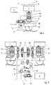
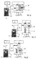
- Fig. 1 such, known from the prior art, active suspension system in the form of a so-called quarter-vehicle model is shown in which the body of the motor vehicle, not shown in its entirety by the reference numeral 1 and one of the wheels of the same designated by the reference numeral 2.
- An electronic control unit 3 triggers the received from him, explained in more detail later on signals and takes into account in particular the forces acting on the vehicle and the resulting displacements of the vehicle in particular according to whether it is a stroke, a pitching or a rolling motion.
- changes in the mean ground clearance measured by a travel sensor 4 connected to the control unit 3 indicate that the vehicle is making a lifting movement in one direction or the other relative to the ground.
- Temporal changes in the difference in the mean values of the ground clearances on the front and rear wheels indicate that the body 1 makes pitching movements, ie rotational movements about the transverse axis of the vehicle, in one or the other direction relative to the ground. Further, changes with time in the difference of the average values of the ground clearance of the body on the right and left wheels indicate that the vehicle is rolling in one or the other direction, ie, rotations about the longitudinal axis of the vehicle.
- a control valve 5 Via a control valve 5, the supply and discharge of hydraulic fluid is controlled in a designed as a piston-cylinder unit actuator 6.
- the control valve 5 is actuated by the connected to the encoder 4 control unit 3.
- the displacement sensor 4 generates signals that represent the respective stroke position of the wheels 2 relative to the body 1.
- To the encoder 4 and acceleration sensor 7, 8, 9 and 10 are provided for measuring the acceleration of the body 1 and the wheels 2 and a force transmitter 11 for measuring the force acting on the body 1 force.
- control valve 5 By appropriate control of the control valve 5, ie by the connection of one of the chambers 6a or 6b of the actuator 6 with a pressure source 12 designed as a pressure source and the other chamber 6b or 6a with a tank 13, the pressure in the two chambers 6a, 6b of the actuator 6 are varied so that there is a resultant force on a piston 14 of the actuator 6. About the control valve 5, the actuator 6 with respect to the feed pump 12 and the tank 13 can be locked.
- control valve 5 can thus be controlled in such a manner that the inflow of pressure medium is metered into one of the chambers of the actuator 6 from the feed pump 12, while the outflow of hydraulic fluid from the other chamber is metered to the tank 13.
- a more detailed embodiment of an active suspension system known from the prior art is known.
- a spring element 15 for supporting the static vehicle load whereby the dimensioning of the pressure supply, that is substantially that of the feed pump 12, can be reduced.
- the spring element 15 also serves as a safety component, which receives the static load of the vehicle in the event of failure of the hydraulic control or the electronic control unit 3.
- the hydraulic control for the suspension system consists of a control valve 5 associated with each of the wheels 2 and a plurality of shut-off valves 16 per vehicle axle in one embodiment as a seat valve. In this way it is avoided that when the vehicle is the set altitude of the same changes due to leaks of the control valve 5 designed as a slide valve.
- the pressure supply has the normally driven by a serving as a drive source for the motor vehicle engine 17 feed pump 12, a continuously controllable throttle valve 18 which is connected to the suction control of the feed pump 12 between the same and the tank 13 and an adjustment of the sucked by the feed pump 12 volume flow allows, which leads to a reduction of energy consumption, as well as a pressure control valve 19 for throttle-free connection between the pressure side of the feed pump 12 and the tank 13.
- a pressure control valve 19 for throttle-free connection between the pressure side of the feed pump 12 and the tank 13.
- the known suspension system further has an accumulator system consisting of a pressure accumulator 20, a shut-off valve 21 and a pressure sensor 22, which is able to deliver energy at high power requirements. Since such high peak powers are usually required only for a short time, it can be ensured with a suitable design of the pressure accumulator 20 that the feed pump 12 only has to have a comparatively low maximum delivery rate. In extreme driving conditions, the pressure sensor 22 detects pressure fluctuations in the line between the feed pump 12 and the control valve 5, which are a signal that a significantly increased pressure is needed.
- control unit 3 brings at least one of the control valves 5 in a position in which the pressure side of the feed pump 12 with one of the two chambers 6a or 6b of the actuator 6 with a relatively low throttle resistance is connected. Furthermore the check valve 21 of the accumulator 20 is opened and the feed pump 12 is brought by the full opening of the throttle valve 18 to the maximum flow rate, so that at the pressure input line of the control valves 5, the correspondingly high pressure level is available.
- a disadvantage of this known suspension or suspension system is the very high number of components having hydraulic system and the fact that the control valves 5 must be designed highly dynamic and therefore very expensive or sometimes not feasible.
- the known systems require a very high energy demand, since due to the necessary dynamics of the system, the feed pump 12 at any time a minimum required hydraulic energy, which is also dependent on the speed of the internal combustion engine, must provide. In particular, at maximum speed of the internal combustion engine and maximum excitation by the road results in addition to a very poor controllability of the system.
- the suspension system according to the invention should have the lowest possible weight and low energy consumption and thereby generate the lowest possible cost.
- the delivery pump is fully variable and can be operated only on demand, which compared to known solutions, the energy consumption is significantly reduced.
- the inventive design of the pump has over known solutions to the further advantage that it has a relatively small size and can be mounted very flexible, since it is operated independently and therefore does not need to be installed at a specific location. In this way, in addition to the energy saving explained above, the cost can be further reduced.
- a very simple and uncomplicated control of each actuator results when at least one delivery pump is provided for each actuator. In this way, furthermore, a large number of otherwise necessary hydraulic lines can be saved. Of course, however, can also be activate several actuators with one and the same feed pump.
- the at least one feed pump and the at least one hydraulic control valve device are connected in a modular manner to the wheel.
- a modular unit can be preassembled in a very simple manner in a corresponding assembly with the wheel or a receptacle for the wheel.
- the actuator is designed as a hydraulic cylinder-piston unit with at least one cylinder and at least one piston. Such an embodiment of the actuator has proved to be very advantageous for connecting the wheel to the body.
- the cylinder-piston unit can be formed as a synchronous cylinder, double-acting differential cylinder, single-acting cylinder-piston unit or rotary cylinder is formed.
- the actuator is integrated in a stabilizer. This is also possible with passive Wheel suspension achieve a very low cost, active suspension control.
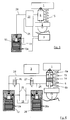
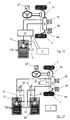
- FIG. 3 shows an active suspension or suspension system according to the invention for springing, damping and / or regulating the relative movements between the vehicle body 1 and the wheel 2.
- an actuator 6 is arranged between the vehicle body 1 and the wheel 2, which is controlled by a hydraulic Control valve device 23 is connected to the feed pump 12.
- a supply line 24 leads to the hydraulic control valve device 23 and from there to one or two only in 4 illustrated chambers 6a and 6b of the actuator 6.
- a return line 25 the hydraulic fluid is fed back to the tank 13.
- the feed pump 12 is independent of the drive source of the motor vehicle drivable and designed for a high frequency intermittent working operation.
- the term "high frequency” here frequencies are considered from 500 Hz.
- the feed pump 12 in the present case piezoelectric actuators 12a as conveying elements.
- This embodiment of the feed pump 12, which is also referred to as a piezo pump provides a fully variable, highly dynamic control of the actuator 6, so that a very fast switching of the actuator 6 is possible, whereby a very good compromise between driving safety and driving comfort is achieved, the costs and the weight of the suspension system can be reduced and the energy consumption of the same is reduced.
- the spring element 15 may be provided which carries at least the static vehicle load and also provides additional security in the event of failure of the electrical control unit 3 or the hydraulic control valve device 23.
- 15 could be completely dispensed with the spring element.
- the hydraulic control valve device 23 has two designed as 2/2-way valves electrical switching and control valves 26 and 27, which serve to control the hydraulic pressure generated by the first feed pump 12 and a second feed pump 28 provided in this case.
- the second feed pump 28 also has piezoelectric actuators 28a as conveying elements in the present case.
- the control valves 26 and 27 may also be designed as pressure control valves and the pressure of the chambers 6a and 6b to control so that a targeted pressure curve takes place during compression or rebound.
- the supplied with the hydraulic fluid or hydraulic pressure actuator 6 is formed as a hydraulic GleichgangZylinder-piston unit and has the two above-mentioned chambers 6a and 6b.
- the control valve 26 controls the supply or discharge to the upper chamber 6a and the control valve 27 controls the supply or discharge to the lower chamber 6b of the actuator 6.
- the wheel 2 so a total of two feed pumps 12 and 28 are assigned.
- the two control valves 26 and 27 are operated in cooperation with the associated feed pump 12 and 28 of the electronic control unit 3 also provided here. As an alternative to the design of the control valves 26 and 27 as 2/2-way valves, they can also be designed as pressure limiting or pressure control valves. Furthermore, the control valves 26 and 27 can be controlled electromagnetically, piezoelectrically as well as magneto or electrorheological and, if appropriate, can also be replaced by constant diaphragms or throttle points. The control valves 26 and 27 may have a built-in throttle as a damper element as normal switching valves or generate an electrically adjustable damping function as control valves. Of the two feed pumps 12 and 28 respectively leads a supply line 24 to the chamber 6a and 6b of the actuator 6. The two control valves 26 and 27 are arranged in respective branches of the supply lines 24 return lines 25.
- the active suspension system described herein serves, inter alia, to maintain a constant distance of the body 1 to the ground or the road, so that pitching movements at the front and / or rear wheels arising during braking or acceleration of the vehicle should be suppressed.
- the control valves 26 and 27 are arranged so that they allow a flow of hydraulic fluid to the tank 13.
- the tank 13 may be under pressure in all embodiments to improve the suction and / or delivery behavior of the feed pumps 12 and / or 28.
- Similar sensors as in FIGS. 1 and 2 can be used, namely position sensors for measurement the displacement of the actuator 6, acceleration sensors for measuring the rotational and longitudinal accelerations of the body 1 and the vertical accelerations of the wheels 2 and force sensors for measuring the transmitted to the body 1 force.
- position sensors for measurement the displacement of the actuator 6
- acceleration sensors for measuring the rotational and longitudinal accelerations of the body 1 and the vertical accelerations of the wheels 2
- force sensors for measuring the transmitted to the body 1 force.
- pressure sensors can also be used.
- the pitch or pitch of the body 1 is generally suppressed by setting the front and rear suspensions stiffer or harder, whereas the respective other suspensions, ie the suspensions of the rear axle or the front axle, are set softer.
- the compensation of rolling movements when cornering is carried out analogously to the compensation of the pitching movements, wherein, of course, rebound and rebound movements between the left and right wheels of the motor vehicle are compensated.
- the active suspension system should also be able to control dynamic forces caused by the road on the body 1. Such forces arise when the motor vehicle passes over elevations or depressions in the road.
- An adequate damping ratio of the suspension system is desirable because a significant reduction in the transmitted to the body 1, dynamic forces zero damping for the suspension system and thereby an undesirable driving behavior would result. Therefore, during the rebound stroke, the suspension system sets a damping resistance that is generated by controlled operation of the feed pumps 12 and 28 and / or by corresponding throttling of the control valves 26 and 27 in a manner that is possible to selectively control the speed of movement of the piston 14 of the actuator 6.
- a controlled operation of the feed pumps 12 and 28 by regulating the voltage applied to the piezo elements of the feed pumps 12 and 28 voltage and / or by regulating the operating frequency of the feed pumps 12 and 28 is possible.
- the piston 14 of the actuator 6 shifts upward, so that the pressure in the upper chamber 6a increases.
- the pressure in the upper chamber 6a is reduced by a corresponding control of the control valve 26.
- the actuators 6 may also be designed so that in each case the piston 14 is connected to the body 1 and not to the wheel 2. The discharge and increase of pressure of the hydraulic fluid in the two chambers 6a and 6b is then adjusted accordingly. Furthermore, the actuators 6 may also be installed horizontally between the body 1 and the wheels 2. Preferably, the feed pumps 12 and 28 are designed together with the control valves 26 and 27 and the hydraulic control valve device 23 as a module and integrated into the suspension system or directly into the wheel 2.
- the control valves 26 and 27 are preferably designed as seat valves, thereby possess no control edges and have a very good dynamics. Furthermore, poppet valves can be switched very quickly, so that the bandwidth of the active control is increased.
- the control valves 26 and 27 may also have a simple construction, since they can be designed as switching and not as control valves.
- a safety valve 29 is provided with a throttle 29a, which is connected so that in this way the two chambers 6a and 6b of the actuator 6 can be interconnected. This results in the failure of the electrical system, a passive suspension system, which allows operation of the motor vehicle with a constant damping.
- the throttle 29a may also be designed as a constant throttle.
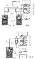
- Fig. 6 shows an embodiment of the suspension system, in which only one feed pump, namely the feed pump 12 is used to control the pressure in the chambers 6a and 6b of the formed in this case as GleichgangZylinder-piston unit actuator 6.
- the hydraulic control valve device 23 has in this case only the control valve 26, which is designed as a 4/2-way valve and ensures that one of the chambers 6a and 6b connected to the feed pump 12 and the other chamber 6b and 6a to the tank 13 is. Trained as a 4/2-way valve control valve 26 may have an integrated damping function by the realization of an electric throttle setting.
- control valve 26 is formed contrary to the illustration as a 4/3-way valve, it may also not shown here have integrated safety function for a possible system failure and thus integrate the function of the safety valve 29 with the throttle 29a of FIG. 5.
- other security measures are conceivable, such as the introduction of additional check valves between the control valve 26 and the actuator 6 possible.
- control valve 26 of FIG. 6 designed as a 4/2-way valve is replaced by two control valves 26 and 27 designed as 3/2-way valves.
- These control valves 26 and 27 may be formed as seat valves and thus have a minimal leakage.
- a safety function is only possible outside of the control valves 26 and 27.
- FIGS 9, 10 and 11 show embodiments of the suspension system, in which each wheel 2 only one Feed pump, namely the feed pump 12, and a control valve, namely the control valve 26, is provided.
- a compromise between the maximum possible bandwidth of the active chassis control system and the system costs can be found, since in this case only one of the chambers 6a or 6b is actively controlled.
- control valve 26 formed in this embodiment as a control valve is provided in the branched from the supply line 24 return line 25 from the chamber 6a of the actuator 6 to the tank 13.
- the control valve 26 may also be designed as a 2/2-way switching valve with integrated throttle, as a proportional valve or as a pressure control valve.
- the chamber 6a opposite the chamber 6a is provided, but this is not supplied with hydraulic fluid. In that regard, it is a single-acting cylinder-piston unit or a plunger.
- FIG. Another embodiment of the suspension system is shown in FIG.
- the two chambers 6a and 6b of the formed as a differential cylinder-piston unit actuator 6 via a check valve 32 and / or a throttle 33 are interconnected.
- the use of the throttle 33 can be dispensed with any other safety measures in case of failure of the suspension system, as behaves the same as a passive suspension system.
- the check valve 32 or the throttle 33 is used.
- a differential cylinder in contrast to a synchronous cylinder, the two opposing surfaces of the piston have different sizes. The use of differential instead of synchronous cylinders occurs in such slow-active chassis for simplicity of the system.
- a pressure accumulator 34 designed, for example, as a gas pressure accumulator may be provided, which branches off from the supply line 24.
- a hydropneumatic embodiment of the suspension system is also without supply of hydraulic fluid through the feed pump 12 and without discharge of hydraulic fluid via the control valve 26 also provided here in a position to spring the wheel 2 relative to the body 1 and can be used in an emergency to to prevent hardening of the chassis.
- the pressure accumulator 34 also serves to reduce the necessary dynamic demand of the control valve device 23 and to avoid the requirement of switching on the feed pump 12 in the case of high-frequency, minor stimuli through the road.
- a supply of hydraulic fluid by the feed pump 12 and a discharge thereof by the control valve 26 is only required if the suspension system recognizes that the vehicle behavior can be improved by an active intervention. In this way, the design of the feed pump 12 can be reduced in terms of their capacity.
- the constant throttle 33 ensures in this case that the pressure accumulator 34 can act as a spring element with additional damping effect for the suspension system.
- a switching valve 35 is provided with a variable throttle 35a, which increases the variability possibilities of the suspension system and acts in a similar manner as the throttle 33. For this reason, either the throttle 33 or the throttle 35a of the switching valve 35 could be dispensed with. In principle, both a constant and a variable, electrically adjustable throttle is possible.
- the safety valve 29 with throttle 29a already described with reference to FIG. 5 is provided on the one hand, and, on the other hand, on one or both supply lines 24 respective pressure accumulator 36 connected via corresponding valves 37 with integrated, constant or adjustable throttle, so that the necessary and desirable compliance of the suspension is given, since the pressure accumulator 36 ensure resilient mobility of the piston 14 of the actuator 6.
- the two chambers 6a and 6b are closed by the hydraulic control valve device 23 with respect to the tank 13.
- the chambers 6a and 6b may also be connected to the pressure accumulators 36 in normal operation, as in such a case, regardless of whether the chambers 6a and 6b together or independently closed to the outside or connected to the feed pump 12 or the tank 13 extreme pressure peaks in the chambers 6a and 6b can be avoided even if the actuator 6 is acted upon by strong impact forces with large force or Weggradienten and when a quick response of the control valve device 23 is of minor importance.
- a high-pressure accumulator system 38 is further provided, which has a pressure accumulator 39, a check valve 40 and a pressure sensor 41 and which can provide additional energy at high power consumption. Because such excellence usually only be needed briefly, it can be ensured with appropriate design of the high-pressure accumulator system 38 that the feed pump 12 must have a relatively low flow rate.
- the displacement sensor 4, the acceleration sensor 7, 8, 9 and 10 and the force transmitter 11 are shown in Fig. 12, which can of course be provided in all other embodiments.
- the actuator 6 may in turn be designed as a cylinder-piston unit and in particular as a synchronous cylinder, double-acting differential cylinder, single-acting cylinder-piston unit or rotary cylinder.
- a shock absorber 42 is provided in addition to the actuator 6, not only the spring member 15 but also a shock absorber 42 is provided.
- the shock absorber 42 may be formed as a purely passive damper element, but also as a semi-active shock absorber 42. This can create an active suspension system with easy-to-execute and reliable control, since this can disregard the regulation of fast wheel movements.
- the shock absorber 42 is arranged parallel to the spring member 15 and the actuator 6, in the embodiment of FIG. 14, the shock absorber 42 and the spring member 15 are arranged in parallel and connected in series with the actuator 6.
- the spring element 15 is arranged in series with the actuator 6 and these two elements are arranged parallel to the shock absorber 42.
- the actuator 6 between the body 1 and one of the wheels 2 is arranged.
- the actuator 6 designed in particular as a hydraulic rotary cylinder, is installed in a horizontal or vertical position in a stabilizer 43 of a front and / or rear axle 44 of the motor vehicle, ie between two wheels 2, in order to be able to move in driving conditions which requires stabilization of the chassis, is actively one of passive or possibly adjustable suspension systems independent roll stabilization function by a tension of the two halves of the stabilizer 43 against each other and in both directions to create.
- the feed pump 12 is designed for a high frequency intermittent working operation, whereby similar advantages are achieved as stated above.
- the active function can either be integrated into existing adjustable or active suspension systems or into already existing purely passive systems.
- the integration of the actuator 6 in the stabilizer 43 can thus be independent of the design of the suspension, ie it is applicable to both a passive and any other suspension system.
- the built in the horizontal or vertical position stabilizer 43 is also considered in the present case as belonging to the suspension systems.
- the actuator 6 may be formed as a differential cylinder or as a synchronous cylinder and it may also be installed in the vertical position.
- the stabilizers 43 which are separated, for example, in the middle and the two halves are connected by the actuator 6, can perform a linear and / or rotational movement to influence the ride comfort by reducing the tendency to roll as well as the driving behavior by changing the Einlenk s.
- a torsional moment is generated, for example, as a function of the transverse acceleration occurring at the hydraulic cylinder forming the actuator 6, which causes a support of the body 1 with the aid of the stabilizers 43.
- a lateral acceleration sensor 45 a throttle potentiometer, not shown, a vehicle speed sensor 46 and / or a steering angle sensor 47 can be used.
- the hydraulic control valve device 23 is also provided in this embodiment and connected to the control unit 3.
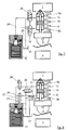
- Fig. 17 shows a further embodiment of the integration of the actuator 6 in the stabilizer 43 of one or both axles of the motor vehicle.
- the hydraulic control valve device 23 similar to the embodiment of Figures 4 and 5, the two control valves 26 and 27, which are arranged in respective return lines 25.
- the two leading to the actuator 6 supply lines 24 are similar to the embodiment of Fig. 5, connected via the safety valve 29 with each other.
- the second delivery pump 28 is provided here in addition to the first delivery pump 12.
- a 4/3-way proportional valve in valve spool design two 3/2-way proportional valves in valve seat design or four 2/2-way proportional valves in valve seat design are used, each of which could be equipped with switching and / or control function, such as a pressure control.
- FIG. 18 Another embodiment of the suspension system with the integration of the actuator 6 in the stabilizer 43 is shown in Fig. 18.
- the feed pump 12 is provided and connected to a designed as a 4/2-way valve control valve 26 to the actuator 6.
- This embodiment is thus similar in terms of the configuration of the hydraulic control valve device 23 to that shown in Fig. 6.
- valve seat design instead of the 4/2 way valve, two 3/2-way valves of valve seat design are provided as switching valves 26 and 27, so that a similar embodiment as in FIG. 7 is present.
- one feed pump 12 may also be an embodiment with a proportional control valve 4/3 valve spool type or four 2/2-way proportional valves in valve seat design, preferably with switching and / or control functions, such as a pressure control, may be provided.
- electrovalves may be provided to avoid in case of system failure during cornering an inclination of the vehicle body when driving straight ahead, as the mutually blocked halves of the stabilizer 43 act in such a case as passive torsion springs.
- any of the embodiment of the suspension system described with reference to FIGS. 3-15, and in particular the hydraulic control valve device 23, may also be used in the embodiment according to FIGS. 16-19, unless there are particular reasons against such an application.
- Fig. 20 is a diagram showing various force-velocity characteristics.
- the curve denoted by “A” represents the progression of the force over the speed in a passive suspension system.
- the characteristic curve labeled “B” represents the possibilities of a semi-active suspension system, with “C” those of a slow-active suspension system and the with “D” designated the map of a fully active suspension system.
Landscapes
- Engineering & Computer Science (AREA)
- Mechanical Engineering (AREA)
- Vehicle Body Suspensions (AREA)
Applications Claiming Priority (1)
| Application Number | Priority Date | Filing Date | Title |
|---|---|---|---|
| DE200610044627 DE102006044627A1 (de) | 2006-09-19 | 2006-09-19 | Aktives Fahrwerkssystem |
Publications (1)
| Publication Number | Publication Date |
|---|---|
| EP1902874A1 true EP1902874A1 (fr) | 2008-03-26 |
Family
ID=38686617
Family Applications (1)
| Application Number | Title | Priority Date | Filing Date |
|---|---|---|---|
| EP07018425A Withdrawn EP1902874A1 (fr) | 2006-09-19 | 2007-09-19 | Système de châssis actif |
Country Status (2)
| Country | Link |
|---|---|
| EP (1) | EP1902874A1 (fr) |
| DE (1) | DE102006044627A1 (fr) |
Cited By (7)
| Publication number | Priority date | Publication date | Assignee | Title |
|---|---|---|---|---|
| DE102008015795A1 (de) * | 2008-03-26 | 2009-10-01 | Trw Automotive Gmbh | Aktives Fahrwerkstabilisierungsystem |
| WO2010019038A1 (fr) * | 2008-08-12 | 2010-02-18 | Nederlandse Organisatie Voor Toegepast-Natuurwetenschappelijk Onderzoek Tno | Système de suspension hydraulique multipoints pour un véhicule terrestre |
| WO2017050564A1 (fr) * | 2015-09-25 | 2017-03-30 | Zf Friedrichshafen Ag | Amortisseur de vibrations et véhicule automobile |
| GB2566543A (en) * | 2017-09-19 | 2019-03-20 | Jaguar Land Rover Ltd | An actuator system |
| EP3580075A4 (fr) * | 2017-02-12 | 2021-01-20 | Clearmotion, Inc. | Actionneur hydraulique à rapport de pression relative dépendant de la fréquence |
| US11207937B2 (en) | 2019-11-20 | 2021-12-28 | DRiV Automotive Inc. | Suspension system for a vehicle |
| US11511592B2 (en) | 2019-12-12 | 2022-11-29 | Ford Global Technologies, Llc | Suspension system for a vehicle |
Citations (18)
| Publication number | Priority date | Publication date | Assignee | Title |
|---|---|---|---|---|
| FR2086346A1 (fr) * | 1970-04-25 | 1971-12-31 | Bosch | |
| EP0284053A2 (fr) | 1987-03-24 | 1988-09-28 | Nissan Motor Co., Ltd. | Suspension active pour automobile, comprenant une fonction de suppression du tangage à caractéristiques de réponses variables |
| EP0371709A1 (fr) | 1988-11-28 | 1990-06-06 | Group Lotus Limited | Dispositif de suspension pour véhicule |
| DE3902743C1 (en) * | 1989-01-31 | 1990-07-26 | Daimler-Benz Aktiengesellschaft, 7000 Stuttgart, De | Active wheel or axle support |
| US5067684A (en) * | 1988-12-22 | 1991-11-26 | Moog Inc. | Vibration-isolating machine mount |
| EP0470166A1 (fr) | 1989-04-24 | 1992-02-12 | Lotus Group Plc | Systeme de controle de la suspension d'un vehicule terrestre. |
| EP0470991A1 (fr) | 1989-05-05 | 1992-02-19 | Lotus Group Plc | Systeme de controle de la suspension d'un vehicule. |
| DE4212839A1 (de) | 1991-04-23 | 1992-11-19 | Lotus Car | Fahrzeugaufhaengung |
| DE3844803C2 (en) | 1988-05-28 | 1993-09-09 | Daimler-Benz Aktiengesellschaft, 70567 Stuttgart, De | Vehicular active suspension with controllable under or over-steer |
| DE4334227A1 (de) * | 1993-10-07 | 1995-04-13 | Fichtel & Sachs Ag | Energiesparendes Hydrauliksystem für aktive Fahrwerke |
| JPH07167189A (ja) * | 1993-12-15 | 1995-07-04 | Toyota Motor Corp | エアサスペンション装置 |
| EP0681533A1 (fr) | 1993-02-04 | 1995-11-15 | Lotus Car | Dispositif de suspension de vehicule. |
| DE19703872A1 (de) * | 1996-02-06 | 1997-08-07 | Tenneco Automotive Inc | Hydraulischer Dämpfer |
| DE19860233A1 (de) | 1998-12-24 | 2000-07-06 | Daimler Chrysler Ag | Aktives Federungssystem |
| DE10213156A1 (de) | 2002-03-23 | 2003-10-02 | Daimler Chrysler Ag | Aktive Federung für ein Kraftfahrzeug |
| DE10216132A1 (de) * | 2002-04-12 | 2003-10-23 | Bayerische Motoren Werke Ag | Aktives Fahrwerksystem eines Fahrzeugs |
| US20040145100A1 (en) * | 2003-01-24 | 2004-07-29 | Damon Delorenzis | Distributed power suspension system |
| DE10330344A1 (de) | 2003-07-05 | 2005-02-24 | Deere & Company, Moline | Hydraulische Federung |
-
2006
- 2006-09-19 DE DE200610044627 patent/DE102006044627A1/de not_active Withdrawn
-
2007
- 2007-09-19 EP EP07018425A patent/EP1902874A1/fr not_active Withdrawn
Patent Citations (18)
| Publication number | Priority date | Publication date | Assignee | Title |
|---|---|---|---|---|
| FR2086346A1 (fr) * | 1970-04-25 | 1971-12-31 | Bosch | |
| EP0284053A2 (fr) | 1987-03-24 | 1988-09-28 | Nissan Motor Co., Ltd. | Suspension active pour automobile, comprenant une fonction de suppression du tangage à caractéristiques de réponses variables |
| DE3844803C2 (en) | 1988-05-28 | 1993-09-09 | Daimler-Benz Aktiengesellschaft, 70567 Stuttgart, De | Vehicular active suspension with controllable under or over-steer |
| EP0371709A1 (fr) | 1988-11-28 | 1990-06-06 | Group Lotus Limited | Dispositif de suspension pour véhicule |
| US5067684A (en) * | 1988-12-22 | 1991-11-26 | Moog Inc. | Vibration-isolating machine mount |
| DE3902743C1 (en) * | 1989-01-31 | 1990-07-26 | Daimler-Benz Aktiengesellschaft, 7000 Stuttgart, De | Active wheel or axle support |
| EP0470166A1 (fr) | 1989-04-24 | 1992-02-12 | Lotus Group Plc | Systeme de controle de la suspension d'un vehicule terrestre. |
| EP0470991A1 (fr) | 1989-05-05 | 1992-02-19 | Lotus Group Plc | Systeme de controle de la suspension d'un vehicule. |
| DE4212839A1 (de) | 1991-04-23 | 1992-11-19 | Lotus Car | Fahrzeugaufhaengung |
| EP0681533A1 (fr) | 1993-02-04 | 1995-11-15 | Lotus Car | Dispositif de suspension de vehicule. |
| DE4334227A1 (de) * | 1993-10-07 | 1995-04-13 | Fichtel & Sachs Ag | Energiesparendes Hydrauliksystem für aktive Fahrwerke |
| JPH07167189A (ja) * | 1993-12-15 | 1995-07-04 | Toyota Motor Corp | エアサスペンション装置 |
| DE19703872A1 (de) * | 1996-02-06 | 1997-08-07 | Tenneco Automotive Inc | Hydraulischer Dämpfer |
| DE19860233A1 (de) | 1998-12-24 | 2000-07-06 | Daimler Chrysler Ag | Aktives Federungssystem |
| DE10213156A1 (de) | 2002-03-23 | 2003-10-02 | Daimler Chrysler Ag | Aktive Federung für ein Kraftfahrzeug |
| DE10216132A1 (de) * | 2002-04-12 | 2003-10-23 | Bayerische Motoren Werke Ag | Aktives Fahrwerksystem eines Fahrzeugs |
| US20040145100A1 (en) * | 2003-01-24 | 2004-07-29 | Damon Delorenzis | Distributed power suspension system |
| DE10330344A1 (de) | 2003-07-05 | 2005-02-24 | Deere & Company, Moline | Hydraulische Federung |
Cited By (12)
| Publication number | Priority date | Publication date | Assignee | Title |
|---|---|---|---|---|
| DE102008015795A1 (de) * | 2008-03-26 | 2009-10-01 | Trw Automotive Gmbh | Aktives Fahrwerkstabilisierungsystem |
| WO2010019038A1 (fr) * | 2008-08-12 | 2010-02-18 | Nederlandse Organisatie Voor Toegepast-Natuurwetenschappelijk Onderzoek Tno | Système de suspension hydraulique multipoints pour un véhicule terrestre |
| EP2156970A1 (fr) * | 2008-08-12 | 2010-02-24 | Nederlandse Organisatie voor toegepast- natuurwetenschappelijk onderzoek TNO | Système de suspension hydraulique multipoint pour véhicule terrestre |
| US8672337B2 (en) | 2008-08-12 | 2014-03-18 | Nederlandse Organisatie Voor Toegepast-Natuurwetenschappelijk Onderzoek Tno | Multi-point hydraulic suspension system for a land vehicle |
| WO2017050564A1 (fr) * | 2015-09-25 | 2017-03-30 | Zf Friedrichshafen Ag | Amortisseur de vibrations et véhicule automobile |
| EP3580075A4 (fr) * | 2017-02-12 | 2021-01-20 | Clearmotion, Inc. | Actionneur hydraulique à rapport de pression relative dépendant de la fréquence |
| US11965531B2 (en) | 2017-02-12 | 2024-04-23 | ClearMotion, Inc. | Hydraulic actuator with a frequency dependent relative pressure ratio |
| GB2566543A (en) * | 2017-09-19 | 2019-03-20 | Jaguar Land Rover Ltd | An actuator system |
| GB2566543B (en) * | 2017-09-19 | 2020-02-05 | Jaguar Land Rover Ltd | An actuator system |
| US11084350B2 (en) | 2017-09-19 | 2021-08-10 | Jaguar Land Rover Limited | Actuator system |
| US11207937B2 (en) | 2019-11-20 | 2021-12-28 | DRiV Automotive Inc. | Suspension system for a vehicle |
| US11511592B2 (en) | 2019-12-12 | 2022-11-29 | Ford Global Technologies, Llc | Suspension system for a vehicle |
Also Published As
| Publication number | Publication date |
|---|---|
| DE102006044627A1 (de) | 2008-03-27 |
Similar Documents
| Publication | Publication Date | Title |
|---|---|---|
| DE60033152T2 (de) | Aktive regelung des fahrverhaltens für ein fahrzeugaufhängungssystem | |
| DE102006002983B4 (de) | Aktives Fahrwerksystem eines Fahrzeugs | |
| DE69737036T2 (de) | Passives kraftfahrzeugaufhängungssystem mit rollregelungsmechanismus | |
| EP0426995B1 (fr) | Système de suspension hydropneumatique | |
| EP1238834B1 (fr) | Système de suspension active d'un véhicule | |
| DE60034230T2 (de) | Passive regelung des fahrverhaltens für ein fahrzeugaufhängungssystem | |
| DE10122542C5 (de) | Vorrichtung zur Regelung von Bewegungen des Aufbaus von Kraftfahrzeugen sowie Federbein für Kraftfahrzeuge | |
| DE102011078262B4 (de) | Einzelradaufhängung mit selbsttätiger Sturzanpassung | |
| DE4136262C2 (de) | Fahrwerk eines Kraftfahrzeuges | |
| EP0819078B1 (fr) | Dispositif servant a compenser les forces transversales agissant sur un vehicule sur rails | |
| DE19703872A1 (de) | Hydraulischer Dämpfer | |
| EP0344493A1 (fr) | Système de suspension active | |
| DE102020113867A1 (de) | Aufhängungssystem für ein Fahrzeug | |
| DE102008028676A1 (de) | Dämpferbetätigte aktive Rollsteuerung | |
| EP1902874A1 (fr) | Système de châssis actif | |
| DE68908846T2 (de) | Hydraulisches Fahrzeugaufhängungssystem. | |
| EP2287024B1 (fr) | Dispositif de réglage du parallélisme | |
| DE102004056610A1 (de) | Verfahren zum Steuern und Regeln eines aktiven Fahrwerksystems | |
| EP0444278B1 (fr) | Dispositif pour le réglage actif de mouvements de la caisse de véhicules automobiles | |
| DE102004039973B4 (de) | Aktive Fahrwerkaufhängung für Fahrzeuge | |
| DE10216132A1 (de) | Aktives Fahrwerksystem eines Fahrzeugs | |
| DE3936987C2 (fr) | ||
| WO2002008001A1 (fr) | Dispositif pour reguler les mouvements de la superstructure d'un vehicule | |
| EP0233522B1 (fr) | Réglage du niveau et de l'inclinaison pour un véhicule | |
| DE19528565A1 (de) | Integriertes aktives/passives Aufhängungssystem für ein Kraftfahrzeug |
Legal Events
| Date | Code | Title | Description |
|---|---|---|---|
| PUAI | Public reference made under article 153(3) epc to a published international application that has entered the european phase |
Free format text: ORIGINAL CODE: 0009012 |
|
| AK | Designated contracting states |
Kind code of ref document: A1 Designated state(s): AT BE BG CH CY CZ DE DK EE ES FI FR GB GR HU IE IS IT LI LT LU LV MC MT NL PL PT RO SE SI SK TR |
|
| AX | Request for extension of the european patent |
Extension state: AL BA HR MK YU |
|
| AKX | Designation fees paid | ||
| STAA | Information on the status of an ep patent application or granted ep patent |
Free format text: STATUS: THE APPLICATION IS DEEMED TO BE WITHDRAWN |
|
| 18D | Application deemed to be withdrawn |
Effective date: 20090507 |
|
| REG | Reference to a national code |
Ref country code: DE Ref legal event code: 8566 |