EP0371966B1 - Reifendrucksensor für kraftfahrzeuge - Google Patents
Reifendrucksensor für kraftfahrzeuge Download PDFInfo
- Publication number
- EP0371966B1 EP0371966B1 EP19880903185 EP88903185A EP0371966B1 EP 0371966 B1 EP0371966 B1 EP 0371966B1 EP 19880903185 EP19880903185 EP 19880903185 EP 88903185 A EP88903185 A EP 88903185A EP 0371966 B1 EP0371966 B1 EP 0371966B1
- Authority
- EP
- European Patent Office
- Prior art keywords
- pressure sensor
- tyre
- contact pin
- contact
- tire
- Prior art date
- Legal status (The legal status is an assumption and is not a legal conclusion. Google has not performed a legal analysis and makes no representation as to the accuracy of the status listed.)
- Expired - Lifetime
Links
- 230000001939 inductive effect Effects 0.000 claims description 4
- 239000012528 membrane Substances 0.000 abstract description 34
- 239000003990 capacitor Substances 0.000 description 10
- 238000011156 evaluation Methods 0.000 description 6
- 238000012544 monitoring process Methods 0.000 description 4
- 238000013016 damping Methods 0.000 description 3
- 230000000903 blocking effect Effects 0.000 description 2
- 230000007547 defect Effects 0.000 description 2
- 238000009434 installation Methods 0.000 description 2
- 229910000831 Steel Inorganic materials 0.000 description 1
- 241000876466 Varanus bengalensis Species 0.000 description 1
- 238000013461 design Methods 0.000 description 1
- 238000011161 development Methods 0.000 description 1
- 230000018109 developmental process Effects 0.000 description 1
- 238000010586 diagram Methods 0.000 description 1
- 239000011521 glass Substances 0.000 description 1
- 230000001771 impaired effect Effects 0.000 description 1
- 230000006698 induction Effects 0.000 description 1
- 239000011810 insulating material Substances 0.000 description 1
- 238000012423 maintenance Methods 0.000 description 1
- 238000004519 manufacturing process Methods 0.000 description 1
- 239000002184 metal Substances 0.000 description 1
- 238000000034 method Methods 0.000 description 1
- 230000003287 optical effect Effects 0.000 description 1
- 230000010355 oscillation Effects 0.000 description 1
- 230000001681 protective effect Effects 0.000 description 1
- 239000010959 steel Substances 0.000 description 1
- 239000000725 suspension Substances 0.000 description 1
- 238000009966 trimming Methods 0.000 description 1
Images
Classifications
-
- B—PERFORMING OPERATIONS; TRANSPORTING
- B60—VEHICLES IN GENERAL
- B60C—VEHICLE TYRES; TYRE INFLATION; TYRE CHANGING; CONNECTING VALVES TO INFLATABLE ELASTIC BODIES IN GENERAL; DEVICES OR ARRANGEMENTS RELATED TO TYRES
- B60C23/00—Devices for measuring, signalling, controlling, or distributing tyre pressure or temperature, specially adapted for mounting on vehicles; Arrangement of tyre inflating devices on vehicles, e.g. of pumps or of tanks; Tyre cooling arrangements
- B60C23/02—Signalling devices actuated by tyre pressure
- B60C23/04—Signalling devices actuated by tyre pressure mounted on the wheel or tyre
- B60C23/0408—Signalling devices actuated by tyre pressure mounted on the wheel or tyre transmitting the signals by non-mechanical means from the wheel or tyre to a vehicle body mounted receiver
-
- G—PHYSICS
- G01—MEASURING; TESTING
- G01L—MEASURING FORCE, STRESS, TORQUE, WORK, MECHANICAL POWER, MECHANICAL EFFICIENCY, OR FLUID PRESSURE
- G01L19/00—Details of, or accessories for, apparatus for measuring steady or quasi-steady pressure of a fluent medium insofar as such details or accessories are not special to particular types of pressure gauges
- G01L19/08—Means for indicating or recording, e.g. for remote indication
- G01L19/12—Alarms or signals
Definitions
- the invention relates to a tire pressure sensor for motor vehicles according to the preamble of patent claim 1.
- a switching element to be actuated by the tire pressure is formed from a reference pressure chamber which is sealed off from the tire by an electrically conductive membrane and carries a contact pin which is insulated in the middle of the bottom of the reference pressure chamber which is due to a certain membrane deflection with sufficient air pressure in the tire, a middle contact zone of the membrane for closing an oscillating circuit.
- EP-A-0 157 205 it is known from EP-A-0 157 205 to fasten two tire pressure sensors of this type with different threshold values for tire pressure monitoring on the wheel rim next to one another in the circumferential direction.
- the aim of the different threshold values is to ensure that in vehicles for which different tire pressures are provided on the front wheels and on the rear wheels, it is possible to replace the wheels between the front and rear axles at any time without having to replace the pressure sensors at the same time.
- the two threshold values are each set to the two different tire pressures.
- an overpressure in the tire can also be determined and displayed on the tires with the lower required tire pressure at the same time, in which the driving comfort and possibly the driving behavior of the vehicle is impaired by the reduced placement of the tire on the road.
- Such monitoring of the tires against overpressure is there with the Tires filled with higher pressure are not possible.
- the correct function of the tire pressure sensor can hardly be monitored after installation on the rim. For example, it is possible that when changing the tire, the membrane of the tire pressure sensor or a protective cap arranged in front of it is pressed in, thereby blocking the switching function of the membrane. In such cases, sufficient tire pressure is indicated in the tire pressure monitoring even if the air pressure is below the threshold value of the tire pressure sensor.
- the aim of the present solution is to make it possible to easily monitor the blocking of the membrane of the sensor by mechanical damage on a tire pressure sensor as well as the maintenance of the required air pressure in the tire between two threshold values.
- the inventive design of the tire pressure sensor with the characterizing features of the main claim has the advantage that at least one further switching element for the tire pressure is also used in the tire pressure sensor, which actuates together with the first switching element through the membrane of the tire pressure sensor at different values of the tire pressure becomes.
- This allows switching thresholds for different tire pressures on the front and rear wheels of the motor vehicle to be implemented in a tire pressure sensor.
- Such a tire pressure sensor can also be used to monitor the tire pressure with regard to different limits, e.g. B. monitor for an upper limit and a lower limit.
- this solution also makes it possible to block the membrane due to mechanical damage after installation on the rim, e.g. B. in the tire assembly by determining that the tire is filled to the prescribed air pressure, but the electronic tire pressure monitoring then indicates an overpressure, since both switching elements of the tire pressure sensor are closed by the membrane deformation
- the second switching element by means of a further contact pin which, with the first contact pin arranged in the center of the reference pressure chamber, is fastened to it in a common passage in the base of the reference pressure chamber.
- This solution does not require any additional operations in the manufacture of the tire pressure sensor, since the two contact pins are inserted together in the reference pressure chamber.
- the contact arrangement can be produced more easily if the second switching element consists of an annular contact body which is guided around the front end of the central contact pin.
- a sleeve-shaped contact body is expediently arranged coaxially with the central contact pin.
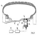
- FIG. 1 shows a cross section through a vehicle wheel with a tire pressure sensor according to the invention and the evaluation circuit in the block diagram
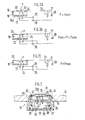
- FIG. 2 shows the schematic representation of the tire pressure sensor according to the invention with two contact pins and the resonant circuit connected thereto a) if the air pressure is too low, b) if the air pressure is sufficient, c) if the tire pressure is too high
- Figure 3 shows a further embodiment of a tire pressure sensor with a sleeve-shaped, coaxially arranged to the central contact pin contact body in cross section.
- FIG. 1 the detail of a motor vehicle wheel is shown in cross-section on a reduced scale and designated 10. It shows a tire 11 which is mounted on a wheel rim 12.
- a tire pressure sensor 13 is inserted in a threaded bore 14 of the wheel rim on an inward trimming of the wheel rim 12.
- a signal pickup 15 is attached to the wheel suspension of the vehicle, not shown, the end face of which is directed towards the tire pressure sensor 13 and couples a high-frequency oscillation generated in an evaluation circuit 16 into the tire pressure sensor 13 if the tire pressure sensor rotates with each revolution of the vehicle wheel 10 comes past.
- An electrical resonant circuit is accommodated in the tire pressure sensor 13, which is closed when a certain air pressure in the tire 11 is reached and then dampens the high-frequency vibration on the signal sensor 15 as a suction circuit.
- This cyclical damping corresponding to the rotating vehicle wheel 10 is monitored in the evaluation circuit 16 for each vehicle wheel. If there is no damping or the damping is reduced, a display 17 indicates which of the monitored tires is under-inflated.
- the schematic structure of the tire pressure sensor 13 and its function is illustrated and explained with the aid of FIG. 2.
- the tire pressure sensor essentially consists of a reference pressure chamber 18, the chamber housing 19 of steel for the tire is closed off by an electrically conductive membrane 20.
- a first contact pin 22 is arranged in an electrically insulated manner in a bushing 21, which acts as a first switching element with the membrane 20.
- the contact pin 22 and the membrane 20 are connected within the tire pressure sensor to a branch of an oscillating circuit 23 which is closed when the air pressure P in the tire is sufficient.
- a further contact pin 24 is fastened in the common bushing 21, insulated from the first contact pin 22.
- This contact pin 24 forms with the diaphragm 20 a second switching element, which is also connected to the resonant circuit 23 and only closes a further resonant circuit 23 when the diaphragm is severely deflected.
- the two adjacent contact pins 22 and 24 are connected to the resonant circuit 23 via a capacitor 25, 26 as a capacitive component with a common coil 27 as an inductive component, the other end of the coil 27 being connected to the membrane 20.
- Another capacitor 28 is connected in parallel with coil 27. This means three states: f1 (both switches open)> f2 (one switch closed)> f3 (both switches closed).
- the externally effective tire pressure P must bulge the membrane 20 against the pressure in the reference pressure chamber 18.
- FIG. 2a it is shown that at a tire pressure P which is below a minimum pressure Pmin predetermined by the lower threshold value of the tire pressure sensor 13, the membrane 20 is not arched inwards to such an extent that it has contact with the contact pins 22 and 23.
- the resonant circuit In this state of the tire pressure sensor 13 (P ⁇ Pmin), 23 is formed from the coil 27 and the capacitor 28.
- the resulting one Resonance frequency f1 is detected by the signal pickup 15 and the evaluation circuit 16. An indication of insufficient air pressure in the tire 11 of the corresponding wheel 10 thus appears on the display 17.
- the reference pressure chamber 18 is shown in a state that occurs. if the tire pressure P is greater than the minimum pressure Pmin specified by the lower threshold value but less than the pressure Pmax specified by the upper threshold value of the tire pressure sensor 10 (Pmin ⁇ P ⁇ Pmax).
- the membrane 20 is arched against the pressure in the reference pressure chamber 18 by the tire pressure P to such an extent that it bears against the central contact pin 22 and thereby closes a circuit branch through which the capacitor 26 is connected in parallel to the capacitor 28 to the coil 27 of the resonant circuit 23 becomes.
- the resonance frequency f2 occurring in this case is now detected by the signal pickup 15 with the evaluation circuit 16 and the display 17 shows that the monitored tire pressure is in order.
- FIG. 3 shows in a further exemplary embodiment the tire pressure sensor 13 screwed into the threaded bore 14 of the wheel rim 12 in cross section.
- the tire pressure sensor 13 consists of a housing 29, preferably made of insulating material, with a threaded attachment 30 for fastening in the threaded bore 14 of the wheel rim 12.
- the housing 29 carries on its side facing the tire 11 the reference pressure chamber 18 with the membrane 20, which is at the front of one perforated cover plate 31 is to be protected against mechanical damage.
- the cover plate 31 is fastened in front of the membrane 20 by a flange 32 of the housing 29.
- In the lower section of the sensor housing 29 there is an oscillating circuit chamber 33 with the coil 27 and the capacitors 25, 26 and 28, which in the arrangement shown in FIG.
- the middle contact pin 22 is melted together with a sleeve-shaped contact body 34 in a glass bushing 21 in the bottom 19a of the chamber housing 19.
- the contact pin 22 carries a contact ball 22a, which bears against a central contact zone of the membrane 20 due to a certain membrane deflection with sufficient air pressure in the tire 11 and thus closes a branch of the resonant circuit 23.
- the upper end of the sleeve-shaped contact body 34 arranged coaxially around the contact pin 22 is set back somewhat from the contact ball 22a of the central contact pin 22 or at the same height, so that the ring-shaped contact zone of the membrane 20 lying over it only becomes stronger when the membrane bends more. creates this contact body 34 and thus closes a further branch of the oscillating circuit 23.
- the sleeve-shaped contact body 34 is connected in parallel with the capacitor 25 and the middle contact pin 22 with the capacitor 26 to the coil 27 of the resonant circuit 23.
- the lower threshold value of the tire pressure sensor 13 is determined by the pressure of the gas filled into the reference pressure chamber 18 via a bore 35.
- the bore is closed pressure-tight by a ball 36 after the gas has been filled in.
- the difference between the lower and upper threshold value of the tire pressure sensor 13 is mainly determined by the distance that the membrane 20 still has when it contacts the contact ball 22a of the central contact pin 22 from the contact body 34 arranged coaxially thereto.
- this tire pressure sensor 13 also monitors whether the air pressure in the tire 11 lies between the two switching thresholds of the tire pressure sensor 13 or whether it falls below the lower switching threshold or exceeds the upper switching threshold. In addition to indicating that the tire pressure is too low for a leaky tire, it is also desirable to recognize an excessive tire pressure because this can damage the tire or impair its properties.
- the cap 31 is pressed in front of the membrane 20 and the membrane 20 has been blocked thereby.
- the membrane 20 rests on both contacts 22, 24 and gives a corresponding indication of a sensor defect or overpressure on the display 17 at the start of the process. Since the display 17 does not differentiate between a sensor defect and overpressure, the tire pressure is first reduced. If the display 17 remains unchanged, the membrane 20 is blocked. A complex check of the function of the tire pressure sensor 13 or an optical check by removing the sensor after each tire assembly can thus be avoided.
- the invention is not restricted to the exemplary embodiments shown.
- separate bushings can be selected for each switching element.
- the sleeve-shaped contact body can be made from a tube section or a bent sheet metal strip. It can also be designed as a pin that carries a contact ring below the membrane.
- a plurality of contact bodies with different distances from the membrane around the central contact pin can also be arranged, which sense different threshold values and close further circuits.
Landscapes
- Physics & Mathematics (AREA)
- General Physics & Mathematics (AREA)
- Engineering & Computer Science (AREA)
- Mechanical Engineering (AREA)
- Measuring Fluid Pressure (AREA)
Description
- Die Erfindung geht aus von einem Reifendrucksensor für Kraftfahrzeuge nach der Gattung des Patentanspruchs 1.
- Bei einem solchen bekannten Reifendrucksensor (DE-A-3 234 854) ist ein vom Reifendruck zu betätigendes Schaltorgan aus einer Referenzdruckkammer gebildet, die zum Reifen hin durch eine elektrisch leitende Membran abgeschlossen ist und einen mitten im Boden der Referenzdruckkammer isoliert durchgeführten Kontaktstift trägt, an dem durch eine bestimmte Membrandurchbiegung bei ausreichendem Luftdruck im Reifen eine mittlere Kontaktzone der Membran zum Schließen eines Schwingkreises anliegt.
- Darüber hinaus ist es aus der EP-A-0 157 205 bekannt, zwei derartige Reifendrucksensoren mit unterschiedlichen Schwellwerten zur Reifendrucküberwachung an der Radfelge in Umfangsrichtung nebeneinander zu befestigen. Durch die unterschiedlichen Schwellwerte soll erreicht werden, daß bei Fahrzeugen, für die an den Vorderrädern und an den Hinterrädern unterschiedliche Reifendrücke vorgesehen sind, ein Austauschen der Räder zwischen Vorder- und Hinterachse jederzeit möglich ist, ohne gleichzeitig auch die Drucksensoren austauschen zu müssen. Die zwei Schwellwerte sind jeweils auf die zwei unterschiedlichen Reifendrücke eingestellt.
- Mit einer derartigen Lösung läßt sich ggf. auch gleichzeitig an den Reifen mit dem geringeren geforderten Reifendruck ein Überdruck im Reifen ermitteln und anzeigen, bei dem der Fahrkomfort und ggf. das Fahrverhalten des Fahrzeugs durch die verringerte Auflage des Reifens auf der Fahrbahn beeinträchtigt wird. Eine solche Überwachung der Reifen gegen Überdruck ist jedoch dort bei den mit höherem Druck gefüllten Reifen nicht möglich. Außerdem kann bei den bekannten Lösungen dieser Art die richtige Funktion des Reifendrucksensors nach dem Einbau an der Felge kaum überwacht werden. So ist es beispielsweise möglich, daß beim Reifenwechsel die Membran des Reifendrucksensors oder eine davor angeordnete Schutzkappe eingedrückt und dadurch die Schaltfunktion der Membran blockiert wird. In solchen Fällen wird bei der Reifendrucküberwachung ein ausreichender Luftdruck im Reifen auch dann angezeigt, wenn der Luftdruck unter dem Schwellwert des Reifendrucksensors liegt.
- Mit der vorliegenden Lösung wird angestrebt, die Möglichkeit zu schaffen, auf einfache Weise an einem Reifendrucksensor das Blockieren der Membran des Sensors durch mechanische Beschädigung sowie die Einhaltung des erforderlichen Luftdrucks im Reifen zwischen zwei Schwellwerten zu überwachen.
- Die erfindungsgemäße Ausbildung des Reifendrucksensors mit den kennzeichnenden Merkmalen des Hauptanspruchs hat den Vorteil, daß auf einfache Weise mindestens ein weiteres Schaltorgan für den Reifendruck in den Reifendrucksensor mit eingesetzt wird, das gemeinsam mit dem ersten Schaltorgan durch die Membran des Reifendrucksensors bei unterschiedlichen Werten des Reifendrucks betätigt wird. Dadurch lassen sich Schaltschwellen für unterschiedliche Reifendrücke an den Vorder- und Hinterrädern des Kraftfahrzeuges in einem Reifendrucksensor realisieren. Ebensogut läßt sich ein solcher Reifendrucksensor aber auch zur Überwachung des Reifendrucks im Hinblick auf verschiedene Grenzen z. B. auf eine Obergrenze und eine Untergrenze überwachen. Schließlich ist es durch diese Lösung auch noch ohne weiteres möglich, ein Blockieren der Membrane durch mechanische Beschädigungen nach dem Einbau an der Felge, z. B. bei der Reifenmontage dadurch festzustellen, daß der Reifen auf den vorgeschriebenen Luftdruck gefüllt wird, die elektronische Reifendruck-Überwachung jedoch dann einen Überdruck anzeigt, da beide Schaltorgane des Reifendrucksensors durch die Membranverformung geschlossen sind
- Durch die in den Unteransprüchen aufgeführten Maßnahmen sind vorteilhafte Weiterbildungen und Verbesserungen der im Hauptanspruch angegebenen Merkmale möglich. Besonders vorteilhaft ist es, das zweite Schaltorgan durch einen weiteren Kontaktstift zu realisieren, der mit dem in der Mitte der Referenzdruckkammer angeordneten ersten Kontaktstift von diesem isoliert in einer gemeinsamen Durchfürung im Boden der Referenzdruckkammer befestigt ist. Diese Lösung erfordert keine zusätzlichen Arbeitsgänge bei der Herstellung des Reifendrucksensors, da beide Kontaktstifte gemeinsam in die Referenzdruckkammer eingesetzt werden. Außerdem läßt sich die Kontaktanordnung leichter herstellen, wenn das zweite Schaltorgan aus einem ringförmigen Kontaktkörper besteht, der um das vordere Ende des mittleren Kontaktstiftes herumgeführt ist. Zweckmäßigerweise ist dabei ein hülsenförmiger Kontaktkörper koaxial zu dem mittleren Kontaktstift angeordnet.
- Ausführungsbeispiele der Erfindung sind in der Zeichnung dargestellt und in der nachfolgenden Beschreibung näher erläutert. Es zeigen Figur 1 einen Querschnitt durch ein Fahrzeugrad mit einem erfindungsgemäßen Reifendrucksensor und der Auswerteschaltung im Blockschaltbild, Figur 2 die schematische Darstellung des erfindungsgemäßen Reifendrucksensors mit zwei Kontaktstiften und dem daran angeschlossenen Schwingkreis a) bei zu geringem Luftdruck, b) bei ausreichendem Luftdruck, c) bei zu hohem Luftdruck im Fahrzeugreifen und Figur 3 zeigt als weiteres Ausführungsbeispiel einen Reifendrucksensor mit einem hülsenförmigen, koaxial zum mittleren Kontaktstift angeordneten Kontaktkörper im Querschnitt.
- In Figur 1 ist der Ausschnitt eines Kraftfahrzeugrades in verkleinertem Maßstab im Querschnitt dargestellt und mit 10 bezeichnet. Er zeigt einen Reifen 11, der auf einer Radfelge 12 montiert ist. An einem nach innen gerichteten beschnitt der Radfelge 12 ist ein Reifendrucksensor 13 in einer Gewindebohrung 14 der Radfelge eingesetzt. In geringem Abstand dazu ist im Bereich des Reifendrucksensors 13 an der nicht dargestellten Radaufhängung des Fahrzeugs ein Signalaufnehmer 15 befestigt, dessen Stirnseite zum Reifendrucksensor 13 hin gerichtet ist und eine in einer Auswerteschaltung 16 erzeugte hochfrequente Schwingung in den Reifendrucksensor 13 einkoppelt, wenn dieser bei jeder Umdrehung des Fahrzeugrades 10 vorbeikommt. Im Reifendrucksensor 13 ist ein elektrischer Schwingkreis untergebracht, der beim Erreichen eines bestimmten Luftdrucks im Reifen 11 geschlossen wird und dann als Saugkreis die hochfrequente Schwingung am Signalaufnehmer 15 bedämpft. Diese bei umlaufendem Fahrzeugrad 10 entsprechend zyklische Bedämpfung wird in der Auswerteschaltung 16 für jedes Fahrzeugrad überwacht. Beim Ausbleiben oder bei Verringerung der Bedämpfung wird auf einer Anzeige 17 signalisiert, welcher der überwachten Reifen einen zu geringen Luftdruck hat.
- Der schematische Aufbau des Reifendrucksensors 13 und seine Funktion wird mit Hilfe der Figur 2 dargestellt und erläutert. Der Reifendrucksensor besteht im wesentlichen aus einer Referenzdruckkammer 18, deren Kammergehäuse 19 aus Stahl zum Reifen hin durch eine elektrisch leitende Membran 20 abgeschlossen ist. Im Gehäuseboden 19a der Referenzdruckkammer 18 ist in der Bodenmitte in einer Durchführung 21 ein erster Kontaktstift 22 elektrisch isoliert angeordnet, der als ein erstes Schaltorgan mit der Membran 20 zusammenwirkt. Der Kontaktstift 22 und die Membran 20 sind innerhalb des Reifendrucksensors mit einem Zweig eines Schwingkreises 23 verbunden, der bei ausreichendem Luftdruck P im Reifen geschlossen wird.
- Neben dem mitten im Gehäuseboden 19a der Referenzdruckkammer 18 angeordneten ersten Kontaktstift 22 ist ein weiterer Kontaktstift 24 vom ersten Kontaktstift 22 isoliert in der gemeinsamen Durchführung 21 befestigt. Dieser Kontaktstift 24 bildet mit der Membran 20 ein zweites Schaltorgan, das ebenfalls am Schwingkreis 23 angeschlossen ist und erst bei einer stärkeren Membrandurchbiegung einen weiteren Schwingkreis 23 schließt. Gemäß Figur 2 sind die beiden nebeneinander angeordneten Kontaktstifte 22 und 24 über je einen Kondensator 25, 26 als kapazitive Komponente mit einer gemeinsamen Spule 27 als induktive Komponente zu dem Schwingkreis 23 verschaltet, wobei das andere Ende der Spule 27 mit der Membran 20 verbunden ist. Parallel zur Spule 27 liegt noch ein weiterer Kondensator 28. Dies bedeutet drei Zustände: f1 (beide Schalter offen) > f2 (ein Schalter zu) > f3 (beide Schalter zu).
- Da die Referenzdruckkammer 18 des Reifendrucksensors 13 mit einem Gas auf einen vorbestimmten Druck gefüllt ist, muß der von außen wirksame Reifendruck P die Membran 20 gegen den Druck in der Referenzdruckkammer 18 durchwölben. In Figur 2a ist dargestellt, daß bei einem Reifendruck P, der unterhalb eines durch den unteren Schwellwert des Reifendrucksensor 13 vorgegebenen Mindestdruck Pmin liegt, die Membran 20 nicht soweit nach innen durchgewölbt ist, daß sie Kontakt hat zu den Kontaktstiften 22 und 23. Der Schwingkreis 23 wird bei diesem Zustand des Reifendrucksensors 13 (P < Pmin) aus der Spule 27 und den Kondensator 28 gebildet. Die sich daraus ergebende Resonanzfrequenz f1 wird vom Signalaufnehmer 15 und der Auswerteschaltung 16 detektiert. Auf der Anzeige 17 erscheint dadurch ein Hinweis auf zu geringem Luftdruck im Reifen 11 des entsprechenden Rades 10.
- In Figur 2b ist die Referenzdruckkammer 18 in einem Zustand dargestellt, der auftritt. wenn der Reifendruck P größer als der durch den unteren Schwellwert vorgegebenen Mindestdruck Pmin aber kleiner als der durch den oberen Schwellwert des Reifendrucksensors 10 vorgegebenen Druckes Pmax ist (Pmin < P < Pmax). Die Membran 20 ist hier gegen den Druck in der Referenzdruckkammer 18 durch den Reifendruck P soweit durchgewölbt, daß sie am mittleren Kontaktstift 22 anliegt und dadurch einen Schaltungszweig schließt, durch den der Kondensator 26 zusätzlich zum Kondensator 28 zu der Spule 27 des Schwingkreises 23 parallel geschaltet wird. Die dabei auftretende Resonanzfrequenz f2 wird nun vom Signalaufnehmer 15 mit der Auswerteschaltung 16 erfaßt und auf der Anzeige 17 wird kenntlich gemacht, daß der überwachte Reifendruck in Ordnung ist.
- In Figur 2c ist die Membran 20 der Referenzdruckkammer 18 mit einem Reifendruck P beaufschlagt, der größer ist als der obere Schwellwert Pmax des Reifendrucksensors 13 (P < Pmax). Die Membran 20 ist jetzt soweit durchgewölbt, daß sie sowohl am mittleren Kontaktstift 22 als auch an dem benachbarten Kontaktstift 24 anliegt. Dadurch wird ein weiterer Stromkreis mit dem Kondensator 25 geschlossen, der ebenfalls zur Spule 27 des Schwingkreises 23 parallel geschaltet ist. Dies ergibt eine weitere Resonanzfrequenz f3. Sie wird über den Aufnehmer 15 von der Auswerteschaltung 16 erfaßt und über die Anzeige 17 wird dem Fahrer ein Hinweis auf einen zu hohen Luftdruck im überwachten Reifen 11 gegeben.
- Figur 3 zeigt in einem weiteren Ausfürungsbeispiel den Reifendrucksensor 13 eingeschraubt in die Gewindebohrung 14 der Radfelge 12 im Querschnitt. Der Reifendrucksensor 13 besteht aus einem Gehäuse 29, vorzugsweise aus Isolierstoff, mit einem Gewindeansatz 30 zur Befestigung in der Gewindebohrung 14 der Radfelge 12. Das Gehäuse 29 trägt an seiner dem Reifen 11 zugewandten Seite die Referenzdruckkammer 18 mit der Membran 20, die vorn von einer gelochten Abdeckscheibe 31 gegen mechanische Beschädigung geschützt werden soll. Die Abdeckscheibe 31 ist durch einen Bördelrand 32 des Gehäuses 29 vor der Membran 20 befestigt. Im unteren Abschnitt des Sensorgehäuses 29 befindet sich eine Schwingkreiskammer 33 mit der Spule 27 und den Kondensatoren 25, 26 und 28, die in der aus Figur 2 erkennbaren Anordnung miteinander und mit den Schaltorganen des Reifendrucksensors 13 zu einem Schwingkreis 23 verschaltet sind. Der mittlere Kontaktstift 22 ist gemeinsam mit einem hülsenförmigen Kontaktkörper 34 in einer Glasdurchführung 21 im Boden 19a des Kammergehäuses 19 eingeschmolzen. Am vorderen Ende trägt der Kontaktstift 22 eine Kontaktkugel 22a, die durch eine bestimmte Membrandurchbiegung bei ausreichendem Luftdruck im Reifen 11 an einer mittleren Kontaktzone der Membran 20 anliegt und damit einen Zweig des Schwingkreises 23 schließt. Das obere Ende des koaxial um den Kontaktstift 22 angeordneten hülsenförmigen Kontaktkörper 34 ist gegenüber der Kontaktkugel 22a des mittleren Kontaktstiftes 22 etwas zurückgesetzt oder auf gleicher Höhe, so daß die darüberliegende ringförmige Kontaktzone der Membran 20 erst bei einer stärkeren Membrandurchbiegung sich an. diesen Kontaktkörper 34 anlegt und damit einen weiteren Zweig des Schwinkreises 23 schließt. Der hülsenförmige Kontaktkörper 34 ist hier mit dem Kondensator 25 und der mittlere Kontaktstift 22 mit dem Kondensator 26 zur Spule 27 des Schwingkreises 23 parallel geschaltet.
- Der untere Schwellwert des Reifendrucksensors 13 wird durch den Druck des in die Referenzdruckkammer 18 über eine Bohrung 35 eingefüllten Gases bestimmt. Die Bohrung wird durch eine Kugel 36 nach dem Einfüllen des Gases druckdicht verschlossen. Die Differenz zwischen dem unteren und oberen Schwellwert des Reifendrucksensors 13 wird hauptsächlich durch den Abstand bestimmt, den die Membrane 20 bei Anlage an der Kontaktkugel 22a des mittleren Kontaktstiftes 22 noch zu dem koaxial dazu angeordneten Kontaktkörper 34 aufweist.
- In gleicher Weise, wie zu Figur 2 erläutert, wird auch mit diesem Reifendrucksensor 13 überwacht, ob der Luftdruck im Reifen 11 zwischen den zwei Schaltschwellen des Reifendrucksensors 13 liegt bzw. die untere Schaltschwelle unterschreitet oder die obere Schaltschwelle überschreitet. Neben der Anzeige eines zu geringen Reifendrucks bei einen undichten Reifen ist es auch erwünscht, einen überhöhten Reifendruck zu erkennen, weil dadurch der Reifen geschädigt werden kann bzw. sich seine Eigenschaften verschlechtern.
- Außerdem kann durch einen derartigen Reifendrucksensor 13 auf einfache Weise festgestellt werden, ob nach dem Einbau des Reifendrucksensors 13 in die Radfelge 11, z. B. beim Montieren oder beim Auswechseln eines Reifens die Abdeckkappe 31 vor der Membran 20 eingedrückt und die Membran 20 dadurch blockiert worden ist. In diesem Fall liegt die Membran 20 an beiden Kontakten 22, 24 auf und gibt mit Fartbeginn auf der Anzeige 17 einen entsprechenden Hinweis auf einen Sensordefekt bzw. auf Überdruck. Da die Anzeige 17 zwischen einem Sensordefekt und Überdruck nicht unterscheidet, wird der Reifendruck zunächst verringert. Bleibt die Anzeige 17 dabei unverändert, ist die Membran 20 blockiert. Eine aufwendige Überprüfung der Funktion des Reifendrucksensors 13 oder eine optische Kontrolle durch Herausnehmen des Sensors nach jeder Reifenmontage kann so vermieden werden.
- Die Erfindung ist nicht auf die dargestellte Ausführungsbeispiele beschränkt. So können im Boden der Referenzdruckkammer getrennte Durchführungen für jedes Schaltorgan gewählt werden. Der hülsenförmige Kontaktkörper kann aus einem Rohrabschnitt oder einem gebogenen Blechstreifen hergestellt sein. Er kann auch als Stift ausgebilbet sein, der unterhalb der Membran einen Kontaktring trägt. Außerdem können auch mehrere Kontaktkörper mit unterschiedlichen Abständen zur Membran um den mittleren Kontaktstift herum angeordnet sein, die unterschiedliche Schwellwerte abfühlen und weitere Stromkreise schließen. Ferner ist es im Rahmen der Erfindung möglich, anstelle eines Schwingkreises mit dem zu den Schaltorganen in Reihe liegenden Kondensatoren die Schaltorgane an Abgriffe der Induktionsspule anzuschließen.
Claims (6)
Applications Claiming Priority (2)
| Application Number | Priority Date | Filing Date | Title |
|---|---|---|---|
| DE3723510 | 1987-07-16 | ||
| DE19873723510 DE3723510A1 (de) | 1987-07-16 | 1987-07-16 | Reifendrucksensor fuer kraftfahrzeuge |
Publications (2)
| Publication Number | Publication Date |
|---|---|
| EP0371966A1 EP0371966A1 (de) | 1990-06-13 |
| EP0371966B1 true EP0371966B1 (de) | 1991-04-17 |
Family
ID=6331688
Family Applications (1)
| Application Number | Title | Priority Date | Filing Date |
|---|---|---|---|
| EP19880903185 Expired - Lifetime EP0371966B1 (de) | 1987-07-16 | 1988-04-22 | Reifendrucksensor für kraftfahrzeuge |
Country Status (6)
| Country | Link |
|---|---|
| US (1) | US5035137A (de) |
| EP (1) | EP0371966B1 (de) |
| JP (1) | JPH02504129A (de) |
| DE (2) | DE3723510A1 (de) |
| ES (1) | ES2007963A6 (de) |
| WO (1) | WO1989000511A1 (de) |
Families Citing this family (33)
| Publication number | Priority date | Publication date | Assignee | Title |
|---|---|---|---|---|
| DE3815677A1 (de) * | 1988-05-07 | 1989-11-16 | Bosch Gmbh Robert | Drucksensor zur erfassung des reifendrucks |
| US5274355A (en) * | 1992-02-05 | 1993-12-28 | Louis Galan | System for monitoring pressure and temperature of pneumatic tires on a moving vehicle |
| US5289161A (en) * | 1992-05-14 | 1994-02-22 | Huang Tien Tsai | Tire pressure indicator |
| JPH0719981A (ja) * | 1993-06-01 | 1995-01-20 | Nippondenso Co Ltd | 高温用圧力センサ |
| US5526692A (en) * | 1993-12-29 | 1996-06-18 | Keiser Corporation | Sensor |
| US5731754A (en) * | 1994-06-03 | 1998-03-24 | Computer Methods Corporation | Transponder and sensor apparatus for sensing and transmitting vehicle tire parameter data |
| US5844130A (en) * | 1996-04-03 | 1998-12-01 | Ssi Technologies | Apparatus for maintaining a constant radial distance between a transmitting circuit and an antenna coil |
| US6335690B1 (en) | 1997-01-15 | 2002-01-01 | Algonquin Scientific, Llc | Fluid sensing system |
| US6756892B2 (en) | 1997-01-15 | 2004-06-29 | Algonquin Scientific, Llc | Tire pressure sensing system |
| US6362732B1 (en) | 1997-01-15 | 2002-03-26 | Algonquin Scientific Llc | Tire pressure sensing system |
| US6124787A (en) * | 1997-01-15 | 2000-09-26 | Algonquin Scientific, Llc | Tire pressure sensing system |
| US6058768A (en) * | 1997-12-08 | 2000-05-09 | Huang; Tien-Tsai | Apparatus for detecting pressure condition in a pneumatic tire |
| EP0933236A1 (de) * | 1998-02-02 | 1999-08-04 | Tien-Tsai Huang | Vorrichtung zum Erkennen des Reifendruckzustandes |
| DE19853126B4 (de) * | 1998-11-18 | 2005-03-03 | Daimlerchrysler Ag | Verfahren zur Niveauregelung und Radfahrzeug mit einem Niveauregelsystem |
| US6166698A (en) * | 1999-02-16 | 2000-12-26 | Gentex Corporation | Rearview mirror with integrated microwave receiver |
| US8266465B2 (en) | 2000-07-26 | 2012-09-11 | Bridgestone Americas Tire Operation, LLC | System for conserving battery life in a battery operated device |
| US7161476B2 (en) | 2000-07-26 | 2007-01-09 | Bridgestone Firestone North American Tire, Llc | Electronic tire management system |
| DE10103974B4 (de) * | 2001-01-30 | 2006-03-09 | Key Safety Systems, Inc., Sterling Heights | Vorrichtung zur Prüfung des Fülldruckes eines Airbag-Gasspeichers |
| JP2003054230A (ja) * | 2001-08-16 | 2003-02-26 | Sumitomo Rubber Ind Ltd | タイヤ空気圧低下検出方法および装置、ならびにタイヤ減圧判定しきい値の選択プログラム |
| DE10146561A1 (de) * | 2001-09-21 | 2003-04-10 | Bayerische Motoren Werke Ag | Airbagsystem für ein Kraftrad |
| JP4372004B2 (ja) * | 2002-06-20 | 2009-11-25 | ブリヂストン・フアイヤーストーン・ノース・アメリカン・タイヤ・エルエルシー | 過熱したタイヤを検出する装置 |
| US6945104B2 (en) * | 2003-10-24 | 2005-09-20 | Lear Corporation | Attachment mechanism for a tire monitoring system |
| US7086412B2 (en) * | 2003-10-24 | 2006-08-08 | Lear Corporation | Snap-in grommet for a valve steam assembly |
| US20050087007A1 (en) * | 2003-10-24 | 2005-04-28 | Lear Corporation | Tire monitor system with spring retention clip |
| US7086411B2 (en) * | 2003-10-24 | 2006-08-08 | Lear Corporation | Snap-in grommet for a valve stem assembly |
| US7028541B2 (en) * | 2003-11-04 | 2006-04-18 | Lear Corporation | Tire pressure sensing component for detecting air pressure and related method |
| US7336164B2 (en) * | 2006-02-23 | 2008-02-26 | Dymos Co., Ltd. | Tire pressure monitoring system and sensor therefor |
| US7509850B1 (en) * | 2007-09-10 | 2009-03-31 | David Hui | Vehicle protection device directly formed on inflation valve |
| US20090085733A1 (en) * | 2007-09-27 | 2009-04-02 | Kisan Technologies, Inc. | Tire pressure, speed and acceleration monitoring system and method |
| US7937998B2 (en) * | 2009-03-19 | 2011-05-10 | Deere & Company | Sensor mount with self-tightening device |
| US20130167485A1 (en) * | 2011-12-28 | 2013-07-04 | James V. Ireland | Tire pressure sensor storge unit and method |
| US20150107338A1 (en) * | 2014-12-28 | 2015-04-23 | Ronald Billett | Pressure Measurement Device and Method |
| US11745549B2 (en) * | 2017-08-21 | 2023-09-05 | Sram. Llc | Pressure sensing assembly for a bicycle wheel |
Family Cites Families (9)
| Publication number | Priority date | Publication date | Assignee | Title |
|---|---|---|---|---|
| US2274557A (en) * | 1940-07-10 | 1942-02-24 | Morgan Raymond | Electric gauge |
| FR2280521A1 (fr) * | 1974-08-02 | 1976-02-27 | Vesnic Borislav | Avertisseur d'anomalies de pression des pneumatiques |
| FR2351399A1 (fr) * | 1976-05-12 | 1977-12-09 | Lucas Electrical Co Ltd | Transducteur de pression de fluide |
| US4163964A (en) * | 1977-03-21 | 1979-08-07 | Texas Instruments Incorporated | Pneumatic or hydraulic pressure sensors with several thresholds of response |
| DE2832447A1 (de) * | 1978-07-24 | 1980-02-14 | Bosch Gmbh Robert | Pneumatisch betaetigbarer druckschalter |
| DE3243854A1 (de) * | 1982-11-26 | 1984-05-30 | Robert Bosch Gmbh, 7000 Stuttgart | Pneumatisch betaetigbarer druckschalter zur reifendruckueberwachung |
| DE3412949A1 (de) * | 1984-04-06 | 1985-10-17 | Dr.Ing.H.C. F. Porsche Ag, 7000 Stuttgart | Vorrichtung zur kontrolle des luftdrucks von fahrzeugreifen |
| DE3507253C1 (de) * | 1985-03-01 | 1986-07-03 | Dr.Ing.H.C. F. Porsche Ag, 7000 Stuttgart | Pneumatisch betaetigter Druckschalter zur Reifendruckueberwachung |
| DE3738413C1 (en) * | 1987-11-12 | 1989-02-16 | Bosch Gmbh Robert | Tyre pressure sensor for motor vehicles |
-
1987
- 1987-07-16 DE DE19873723510 patent/DE3723510A1/de not_active Withdrawn
-
1988
- 1988-04-22 EP EP19880903185 patent/EP0371966B1/de not_active Expired - Lifetime
- 1988-04-22 DE DE8888903185T patent/DE3862470D1/de not_active Expired - Lifetime
- 1988-04-22 US US07/459,753 patent/US5035137A/en not_active Expired - Fee Related
- 1988-04-22 JP JP63503299A patent/JPH02504129A/ja active Pending
- 1988-04-22 WO PCT/DE1988/000241 patent/WO1989000511A1/de not_active Ceased
- 1988-07-15 ES ES8802230A patent/ES2007963A6/es not_active Expired
Also Published As
| Publication number | Publication date |
|---|---|
| DE3862470D1 (de) | 1991-05-23 |
| US5035137A (en) | 1991-07-30 |
| DE3723510A1 (de) | 1989-01-26 |
| ES2007963A6 (es) | 1989-07-01 |
| EP0371966A1 (de) | 1990-06-13 |
| WO1989000511A1 (fr) | 1989-01-26 |
| JPH02504129A (ja) | 1990-11-29 |
Similar Documents
| Publication | Publication Date | Title |
|---|---|---|
| EP0371966B1 (de) | Reifendrucksensor für kraftfahrzeuge | |
| EP0333708B1 (de) | Reifendrucksensor für kraftfahrzeuge | |
| DE3884506T2 (de) | Reifenprüfeinrichtung. | |
| DE3812633C2 (de) | ||
| DE3151254C2 (de) | Prüfvorrichtung für den Reifenluftdruck von Rädern an Fahrzeugen und Verfahren für eine derartige Vorrichtung | |
| DE2257341A1 (de) | Vorrichtung zum automatischen erkennen unnormaler zustaende in fahrzeugreifen | |
| DE3941780C2 (de) | Druckschalter, insbesondere für eine Warnvorrichtung für Druckverlust in Fahrzeugreifen | |
| DE3543866A1 (de) | Reifendrucksensor fuer kraftfahrzeuge | |
| EP0391922B1 (de) | Reifendrucksensor für kraftfahrzeuge | |
| DE3507253C1 (de) | Pneumatisch betaetigter Druckschalter zur Reifendruckueberwachung | |
| WO1989010852A1 (fr) | Manometre de detection de la pression de pneus | |
| DE112011102738T5 (de) | Elektrodenvorrichtung, Drucksensor und Druckmessgerät | |
| EP0402363B1 (de) | Reifendrucksensor für kraftfahrzeuge | |
| CH665905A5 (de) | Oberschalige elektrische waage. | |
| EP0455636B1 (de) | Reifendrucküberwacher für fahrzeuge | |
| DE4308353C1 (de) | An einem Fahrzeug anzubringender Sensor zur Erkennung einer mechanischen Formveränderung | |
| DE4445819C2 (de) | Abstands/Positions-Meßvorrichtung | |
| EP0335082A2 (de) | Druckschalter zur Überwachung eines Reifenluftdrucks, insbesondere von Kraftfahrzeug-Reifen | |
| DE3709981A1 (de) | Ueberwachungseinrichtung zur erfassung anomaler druckverhaeltnisse von fahrzeugreifen | |
| EP0157205B1 (de) | Vorrichtung zur Kontrolle des Luftdrucks an Fahrzeugreifen | |
| DE3543865A1 (de) | Reifendrucksensor fuer kraftfahrzeuge | |
| DE3738413C1 (en) | Tyre pressure sensor for motor vehicles | |
| DE102018107884A1 (de) | Bedienvorrichtung zum Bedienen von zumindest einem Gerät eines Kraftfahrzeugs, wobei eine Bedienung in Abhängigkeit von zwei physikalischen Parametern durchführbar ist, Kraftfahrzeug sowie Verfahren | |
| DE10110279A1 (de) | Abschirmungs- und Federschnittstelle zwischen einer Zündkerze und einer Stiftspule | |
| WO1996021937A1 (de) | Mechanischer beschleunigungsschalter |
Legal Events
| Date | Code | Title | Description |
|---|---|---|---|
| PUAI | Public reference made under article 153(3) epc to a published international application that has entered the european phase |
Free format text: ORIGINAL CODE: 0009012 |
|
| 17P | Request for examination filed |
Effective date: 19891229 |
|
| AK | Designated contracting states |
Kind code of ref document: A1 Designated state(s): DE FR GB IT SE |
|
| 17Q | First examination report despatched |
Effective date: 19900926 |
|
| GRAA | (expected) grant |
Free format text: ORIGINAL CODE: 0009210 |
|
| AK | Designated contracting states |
Kind code of ref document: B1 Designated state(s): DE FR GB IT SE |
|
| PGFP | Annual fee paid to national office [announced via postgrant information from national office to epo] |
Ref country code: FR Payment date: 19910430 Year of fee payment: 4 |
|
| ET | Fr: translation filed | ||
| GBT | Gb: translation of ep patent filed (gb section 77(6)(a)/1977) | ||
| REF | Corresponds to: |
Ref document number: 3862470 Country of ref document: DE Date of ref document: 19910523 |
|
| PGFP | Annual fee paid to national office [announced via postgrant information from national office to epo] |
Ref country code: DE Payment date: 19910625 Year of fee payment: 4 |
|
| ITF | It: translation for a ep patent filed | ||
| PGFP | Annual fee paid to national office [announced via postgrant information from national office to epo] |
Ref country code: SE Payment date: 19910712 Year of fee payment: 4 |
|
| PLBE | No opposition filed within time limit |
Free format text: ORIGINAL CODE: 0009261 |
|
| STAA | Information on the status of an ep patent application or granted ep patent |
Free format text: STATUS: NO OPPOSITION FILED WITHIN TIME LIMIT |
|
| RAP4 | Party data changed (patent owner data changed or rights of a patent transferred) |
Owner name: ROBERT BOSCH GMBH |
|
| 26N | No opposition filed | ||
| PG25 | Lapsed in a contracting state [announced via postgrant information from national office to epo] |
Ref country code: GB Effective date: 19920422 |
|
| PG25 | Lapsed in a contracting state [announced via postgrant information from national office to epo] |
Ref country code: SE Effective date: 19920423 |
|
| GBPC | Gb: european patent ceased through non-payment of renewal fee | ||
| PG25 | Lapsed in a contracting state [announced via postgrant information from national office to epo] |
Ref country code: FR Effective date: 19921230 |
|
| PG25 | Lapsed in a contracting state [announced via postgrant information from national office to epo] |
Ref country code: DE Effective date: 19930101 |
|
| REG | Reference to a national code |
Ref country code: FR Ref legal event code: ST |
|
| EUG | Se: european patent has lapsed |
Ref document number: 88903185.2 Effective date: 19921108 |
|
| PG25 | Lapsed in a contracting state [announced via postgrant information from national office to epo] |
Ref country code: IT Free format text: LAPSE BECAUSE OF NON-PAYMENT OF DUE FEES Effective date: 20050422 |