EP0372076A1 - Procede de production de feuilles d'acier au silicium directionnel presentant d'excellentes caracteristiques magnetiques et installation de recuit intermediaire continu - Google Patents
Procede de production de feuilles d'acier au silicium directionnel presentant d'excellentes caracteristiques magnetiques et installation de recuit intermediaire continu Download PDFInfo
- Publication number
- EP0372076A1 EP0372076A1 EP88906117A EP88906117A EP0372076A1 EP 0372076 A1 EP0372076 A1 EP 0372076A1 EP 88906117 A EP88906117 A EP 88906117A EP 88906117 A EP88906117 A EP 88906117A EP 0372076 A1 EP0372076 A1 EP 0372076A1
- Authority
- EP
- European Patent Office
- Prior art keywords
- rolling
- silicon steel
- treatment
- steel sheet
- descaling
- Prior art date
- Legal status (The legal status is an assumption and is not a legal conclusion. Google has not performed a legal analysis and makes no representation as to the accuracy of the status listed.)
- Granted
Links
Images


Classifications
-
- C—CHEMISTRY; METALLURGY
- C21—METALLURGY OF IRON
- C21D—MODIFYING THE PHYSICAL STRUCTURE OF FERROUS METALS; GENERAL DEVICES FOR HEAT TREATMENT OF FERROUS OR NON-FERROUS METALS OR ALLOYS; MAKING METAL MALLEABLE, e.g. BY DECARBURISATION OR TEMPERING
- C21D8/00—Modifying the physical properties of ferrous metals or ferrous alloys by deformation combined with, or followed by, heat treatment
- C21D8/12—Modifying the physical properties of ferrous metals or ferrous alloys by deformation combined with, or followed by, heat treatment during manufacturing of articles with special electromagnetic properties
- C21D8/1277—Modifying the physical properties of ferrous metals or ferrous alloys by deformation combined with, or followed by, heat treatment during manufacturing of articles with special electromagnetic properties involving a particular surface treatment
-
- C—CHEMISTRY; METALLURGY
- C21—METALLURGY OF IRON
- C21D—MODIFYING THE PHYSICAL STRUCTURE OF FERROUS METALS; GENERAL DEVICES FOR HEAT TREATMENT OF FERROUS OR NON-FERROUS METALS OR ALLOYS; MAKING METAL MALLEABLE, e.g. BY DECARBURISATION OR TEMPERING
- C21D8/00—Modifying the physical properties of ferrous metals or ferrous alloys by deformation combined with, or followed by, heat treatment
- C21D8/12—Modifying the physical properties of ferrous metals or ferrous alloys by deformation combined with, or followed by, heat treatment during manufacturing of articles with special electromagnetic properties
- C21D8/1294—Modifying the physical properties of ferrous metals or ferrous alloys by deformation combined with, or followed by, heat treatment during manufacturing of articles with special electromagnetic properties involving a localised treatment
Definitions
- This invention relates to a method of producing grain oriented silicon steel sheets having improved magnetic properties and a continuous intermediate annealing equipment therefor, and more particularly it is to advantageously enhance iron loss properties by improving surface state of steel sheets before final cold rolling step among production steps for the grain oriented silicon steel sheet.
- the grain oriented silicon steel sheets are mainly used as a core for transformers and other electrical machineries, and are required to be excellent in the magnetic properties, particularly magnetization property and iron loss property.
- the magnetic properties of the grain oriented silicon steel sheet are strongly affected by not only the sheet quality but also the surface properties. For example, the smaller the surface roughness, the better the magnetic properties as disclosed in Japanese Patent laid open No. 59-38326.
- the surface enriching amount of MnS or MnSe acting as an agent inhibiting normal growth of crystal grain (inhibitor) increases to weaken the inhibitor effect inside the steel sheet in secondary recrystallization annealing step, and consequently the growth of recrystallized grains is insufficient.
- the surface roughness of the finally cold rolled steel sheet becomes rough, not only the unevenness of the surface of the product sheet is large, but also the insulating film formed on the sheet surface is thick and uneven, so that when the product sheet is magnetized, the movement of magnetic domains is obstructed.
- the steel sheet contains 2.5 ⁇ 4.0 wt% (hereinafter shown by % simply) of Si as in the grain oriented silicon steel sheet, it is very brittle and is apt to be broken as compared with the ordinary steel, and also the deformation resistance is very high, so that the cold rolling is generally carried out at a low speed of not more than about 700 mpm using a reverse mill such as sendzimir mill having a small roll diameter (roll diameter: about 80 mm). Therefore, the rolling efficiency is low and the productivity is poor.
- % simply of Si as in the grain oriented silicon steel sheet
- the hot rolled sheet as a base sheet for silicon steel sheet is subjected to two or more-times cold rolling through an intermediate annealing up to a sheet thickness for final product.
- oxidation scale is produced at a thickness of about 0.2 ⁇ 3 ⁇ m on the surface of the steel sheet.
- This oxidation scale consists mainly of silicon dioxide (Si0 2 ) and is very hard and acts to the rolling roll as in abrasive grains to wear the roll surface, which is transferred to a cold rolled sheet to roughen the surface of the steel sheet.
- the applicant have previously proposed a method wherein the silicon steel sheet adhered at its surface with a scale layer after the intermediate annealing is rolled in a cold tandem rolling machine line while descaling with the use of a descaling device particularly arranged between a first stand and a second stand in Japanese Patent laid open No. 63-119925 as a method for reducing the wearing of the rolling roll.
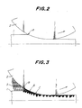
- Fig. 2 is a side view diagrammatically showing a state of clipping the steel sheet by the rolling roll.
- a rolling oil is used for mitigating a rolling load, but this example is a case of using no rolling oil.
- the contact between the rolling roll 2 and the steel sheet 1 starts from a point A. At this point A, the steel sheet 1 begins to cause plastic deformation.
- the steel sheet 1 and the rolling roll 2 metallically contact with each other because of no rolling oil. Therefore, the rolling load considerably increases, and consequently the rolling may be impossible.
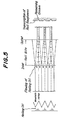
- Fig. 3 shows diagrammatically a state that the steel sheet is clipped into the rolling roll 2 in case of using the rolling oil.
- the viscosity of the rolling oil is large and particularly the diameter of the rolling roll or the rolling speed in the tandem mill is large, the pressure of the rolling oil 3 produced in the wedge passway at the clipped portion of the rolling roll 2 reaches to the yield stress of the steel sheet 1 at a point B on the way to the point A being the contact point between the rolling roll 2 and the steel sheet 1 shown in Fig. 2.
- the steel sheet 1 is subjected to plastic deformation, but this is a free deformation in the rolling oil 3, so that the unevenness is caused in the sheet. Furthermore, the rolling oil 3 enters in the clipped region, and the deformation increases to increase the unevenness.
- the unevenness becomes larger than the thickness of the oil film, the oil film is broken to start the contacting between the roll and the steel sheet at a point C.
- the convex portion of the steel sheet 1 contacted with the rolling roll 2 is flattened by the rolling roll 2, but the concave portion is not flattened because the rolling oil 3 is filled in the concave portion, and hence the concave portion is retained as it is to make the surface of the steel sheet rough.
- FIG. 4 An example of the uneven state is shown in Fig. 4.
- This shows a so-called three-dimensional profile obtained by measuring height direction (Z) of the unevenness while moving a probe in lengthwise direction (X) on the surface of the steel sheet by means of a surface roughness meter, further moving the probe in widthwise direction (Y) by a given position and repeating the same measurement.
- the concave portion of the steel sheet through the rolling oil can be made small by reducing the viscosity of the rolling oil, which never arrives at the level of the bright sheet.
- the inventors have made various studies in order to solve the above problems and found that even when the cold rolling is carried out at a high speed in tandem mill, the steel sheet is subjected to an improving treatment for the surface state of the sheet, i.e. descaling treatment and further a groove forming treatment after the intermediate annealing and before the final cold rolling and then the cold rolling is performed, whereby the surface 'level'of the'steel sheet after the rolling can be raised to that of the bright sheet, and as a result the invention has been accomplished.
- an improving treatment for the surface state of the sheet i.e. descaling treatment and further a groove forming treatment after the intermediate annealing and before the final cold rolling and then the cold rolling is performed, whereby the surface 'level'of the'steel sheet after the rolling can be raised to that of the bright sheet, and as a result the invention has been accomplished.
- the invention lies in a method of producing grain oriented silicon steel sheets having improved magnetic properties by subjecting a hot rolled sheet of silicon steel containing C: 0.02 ⁇ 0.1% and Si: 2.5 ⁇ 4.0% and a small amount of an inhibitor(s) to two or more cold rollings through an intermediate annealing up to a final sheet thickness and then subjecting it to decarburization annealing and finish annealing, characterized in that a final cold rolling in the cold rolling step is a tandem rolling, and an improving treatment for the surface state of said steel sheet is carried out after said intermediate annealing and before said final tandem rolling.
- the invention lies in a continuous intermediate annealing equipment for grain oriented silicon steel sheets, characterized in that a device for improving the surface of the steel sheet is arranged at a delivery side of a continuous annealing furnace.
- C is an element useful not only for effectively contributing to uniformization of hot rolled and cold rolled textures but also for enhancing the alignment of Goss orientation component in the recrystallized texture in the course of repeating the cold rolling and the annealing to final sheet thickness.
- the amount is less than 0.02%, the addition effect is poor, while when it exceeds 0.1%, the temperature of soluting the inhibitor such as S, Se or the like during the slab heating rises to bring about the reduction of the inhibiting force of the inhibitor due to poor solution and also the decarburization in the decarburization annealing becomes difficult. Therefore, the amount is limited to a range of 0.02 ⁇ 0.1%.
- Si effectively contributes to enhance the electric resistance to reduce the iron loss.
- the amount is less than 2.5%, the sufficient reduction of iron loss can not be expected and also a part or whole of the steel sheet is rendered into y transformation during the high temperature annealing to cause disorder of crystal orientation, while when it exceeds 4.0%, the cold workability is considerably degraded. Therefore, the amount is limited to a range of 2.5-4.0%.
- MnS system As the inhibitor, use may be'made of so-called MnS system or AfN system composed of Mn, S, Se, Sb and the like.
- MnS system when using the MnS system, the following composition is preferable.
- Mn 0.03-0.15%
- one or two of S, Se and Sb 0.008-0.080 %
- any of Mn, S, Se and Sb are useful as an inhibitor forming element. However, when these elements are outside the above range, the sufficient inhibiting effect of normal grain growth is not obtained, so that each of these elements is favorable to be added in an amount of the above range.
- Mo may be added in an amount of about 0.005-0.02% for preventing slab breakage during the hot rolling, if necessary.
- molten steel adjusted to the above preferable composition is rendered into a slab through an ingot making-blooming process or a continuous casting process and then subjected to a hot rolling.
- the hot rolled sheet is subjected to 2 or more times cold rolling through an intermediate annealing to a final sheet thickness.
- the smoothening of the steel sheet surface is attained by improving the surface state of the steel sheet after the intermediate annealing and before the final cold rolling.
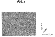
- the steel sheet is subjected to a sweeping treatment such as grinding, polishing or the like to remove oxidation scale produced onto the surface of the steel sheet during the intermediate annealing or further a shallow groove having a depth of about 1 ⁇ 50 ⁇ m is formed along the rolling direction of the steel sheet, preferably within an angle range of +45° with respect to the rolling direction, the steel sheet is subjected to a cold rolling, whereby a smooth surface equal to the level of the bright sheet is obtained onto the surface of the steel sheet as shown in Fig..l.
- a sweeping treatment such as grinding, polishing or the like to remove oxidation scale produced onto the surface of the steel sheet during the intermediate annealing or further a shallow groove having a depth of about 1 ⁇ 50 ⁇ m is formed along the rolling direction of the steel sheet, preferably within an angle range of +45° with respect to the rolling direction
- sweeping of the sheet surface means that the steel sheet surface is ground or polished, for example, by means of a grinding or polishing tool such as a polishing belt using a polishing paper, a cylindrical polishing sleeve, a polishing nonwoven fabric, a brush containing abrasive grains therein or further a wire brush of metal wires.
- a grinding or polishing tool such as a polishing belt using a polishing paper, a cylindrical polishing sleeve, a polishing nonwoven fabric, a brush containing abrasive grains therein or further a wire brush of metal wires.
- the method of improving the surface state of the steel sheet includes a mechanical descaling through a tension leveler, shot blast, rolling machine or a combination thereof, a chemical descaling with hydrochloric acid, sulfuric acid or the like, and a method of performing the sweeping after the removal of oxidation scale through the mechanical descaling or the chemical descaling in addition to the aforementioned sweeping.
- these methods may be selected by taking equipment cost, equipment size, running cost, treating quantity and the like into consideration.
- the above treatment is generally carried out by arranging the surface improving device at an entrance side of the rolling machine.
- the surface improving device when it is arranged at the entrance side of the rolling machine, it should be synchronized with the high rolling speed, so that not only the device is made large but also the control is difficult.
- the sheet passing speed when it is arranged at the delivery side of the intermediate annealing furnace, the sheet passing speed is fairly low, so that the device is made small and the control is easy.
- Fig. 6 is schematically shown a preferable embodiment of the continuous intermediate annealing equipment according to the invention.
- Numerals 10a and lob are entrance side and delivery side loopers, lla, llb and llc bridle rolls, respectively, and 12 a continuous annealing furnace which is comprised of a heating zone 12-a, a soaking zone 12-b and a cooling zone 12-c. And also, 13 is a device for improving the steel sheet surface. The steel sheet surface after the intermediate annealing is improved by the steel sheet surface improving device arranged at the delivery side of the continuous annealing furnace 12.
- the roughness of the rolling roll in at least final pass is not more than 0.30 pm Ra and the viscosity at 50°C of the rolling oil is 2-15 cSt in order to obtain such a smooth surface that the roughness of the sheet surface after the rolling is not more than 0.4 ⁇ m Ra.
- the rolling oil is usually supplied to a sheet or a roll as an emulsion obtained by emulsifying and suspending oil particles into water to extend the oil in the emulsion over the sheet surface and drawn into a wedge-like portion defined by the sheet and the roll at the entrance side of roll bite through hydrodynamics effect (so-called wedge effect) to enter into the roll bite, whereby the concave portion is formed on the steel sheet.
- the roughness of the rolling roll exceeds 0.30 ⁇ m Ra, there is largely caused a fear that the roughness of the sheet surface becomes larger than 0.4 ⁇ m due to the unevenness based on the transcription of the roughness of the rolling roll and the concave portion resulted from the rolling oil, while if the viscosity of the rolling oil at 50°C exceeds 15 cSt, the roughness of the sheet surface is apt to become larger than 0.4 ⁇ m when the high speed rolling is carried out in a tandem rolling machine having a rolling roll diameter of about 600 mm.
- a hot rolled sheet of silicon steel containing C: 0.045%, Si: 3.35%, Mn: 0.065 % , Se: 0.017 % and Sb: 0.027% and having a thickness of 2.5 mm was subjected to a normalized annealing at 1000°C for 30 seconds, pickled, cold rolled to 0.64 mm, and subjected to an_intermediate annealing at 980°C for 90 seconds to prepare three samples A, B and C. Thereafter, the sample A was ground at its surface in parallel to the rolling direction with a polishing belt of grain size #100, while the sample B was ground with the similar polishing belt in a direction perpendicular to the rolling direction as an invention example. Further, the intermediately annealed sample C was used as a comparative example.
- each of these samples was finished to a final sheet thickness of 0.23 mm in a 3-stand tandem mill provided with a rolling roll having a roll diameter of 350 mm and a roll surface roughness of 0.1 ⁇ m Ra at a final stand rolling speed of 1000 mpm with the use of a rolling oil having a viscosity of 8 cSt/50°C and a concentration of 3 % .
- a rolling oil having a viscosity of 8 cSt/50°C and a concentration of 3 % .
- the samples A and B obtained according to the invention are very excellent in not only the surface properties but also the magnetic properties-as compared with the sample C as a comparative example.
- a hot rolled sheet of silicon steel containing C: 0.038%, Si: 3.05%, Mn: 0.070% and S: 0.020% and having a thickness of 2.7 mm was pickled, cold rolled to 0.74 mm, and subjected to an intermediate annealing at 970°C for 40 seconds to prepare three samples D, E and F. Thereafter, as described in Example 1, the sample D was polished at its surface with a brush containing abrasive grains of grain size #240 in parallel to the rolling direction, and the sample E was polished with a similar brush in a direction perpendicular to the rolling direction as an invention example. Further, the intermediately annealed sample F was used as a comparative example.
- each of these samples was finished to a final sheet thickness of 0.27 mm in the same 3-stand tandem mill as in Example 1 at a final stand rolling speed of 1700 mpm with the use of a rolling oil having a viscosity of 15 cSt/50°C and a concentration of 3 % .
- a rolling oil having a viscosity of 15 cSt/50°C and a concentration of 3 % .
- each of these samples was subjected to decarburization annealing, coated with an annealing separator and then subjected to a finish annealing at 860°C for 60 hours and at 1200°C for 5 hours.
- the samples D and E according to the invention are very excellent in not only the surface properties but also the magnetic properties as compared with the sample F as a comparative example.
- a hot rolled sheet containing C: 0.050 % , Si: 3.10%, S: 0.027% and acid soluble Al: 0.030% was subjected to a normalized annealing at 1170 0 C for 90 seconds, cold rolled to a sheet thickness of 0.3 mm, and then subjected to an intermediate annealing at 980°C for 60 seconds to prepare three samples G, H and I. Thereafter, as described in Example 1, the sample G was polished with a brush containing abrasive grains of grain size #240 in parallel to the rolling direction, and the-sample H was polished with a similar brush in a direction perpendicular to the rolling direction as an invention example. Further, the intermediately annealed sample I was used as a comparative example.
- each of these samples was finished to a final sheet thickness of 0.27 mm in the same 3-stand tandem mill as in Example 1 at a final stand rolling speed of 1700 mpm with the use of a rolling oil having a viscosity of 15 cSt/50°C and a concentration of 3%. After the surface average roughness of the portion rolled at the rolling speed of 1700 mpm was measured, each of these samples was subjected to decarburization annealing, coated with an annealing separator and then subjected to a finish annealing at 860°C for 60 hours and at 1200°C for 5 hours.
- the samples G and H according to the invention are very excellent in not only the surface properties but also the magnetic properties as compared with the sample I as a comparative example.
- a hot rolled sheet of silicon steel containing C: 0.045%, Si: 3.35%, Mn: 0.065%, Se: 0.017% and Sb: 0.027% and having a thickness of 2.5 mm was subjected to a normalized annealing at 1000°C for 30 seconds, pickled, cold rolled to 0.64 mm and then subjected to an intermediate annealing at 900°C for 90 seconds to prepare eight samples J, K. L, M, N, 0, P and Q.
- the scale was broken by a tension leveler and swept out by an elastic grinding roll of grain size #240, and the sample K was pickled with hydrochloric acid and subjected to a sweeping with the similar elastic grinding roll, and the sample L was pickled with hydrochloric acid, and the sample M was subjected to a mechanical descaling through shot blast, and the sample N was subjected to a shot blasting and then pickled with sulfuric acid.
- the sample 0 was left after the intermediate annealing.
- each of these samples J ⁇ O was finished to a final sheet thickness of 0.23 mm in a final stand rolling mill having a roll diameter of 600 mm, and a roll roughness of 0.1 ⁇ m Ra at a final stand rolling speed of 1000 mpm and a reduction ratio of 20% with the use of a rolling oil having a viscosity of 2 cSt/50°C and a concentration of 3 % .
- sample P was finished to a final sheet thickness of 0.23 mm in a final stand rolling mill having a roll diameter of 600 mm, and a roll roughness of 0.1 ⁇ m Ra at a final stand rolling speed of 1000 mpm and a reduction ratio of 20% with the use of a rolling oil having a viscosity of 20 cSt/50°C and a concentration of 3%.
- the sample Q was finished to a final sheet thickness of 0.23 mm in a final stand rolling mill having a roll diameter of 600 mm, and a roll roughness of 0.4 ⁇ m Ra at a final stand rolling speed of 1000 mpm and a reduction ratio of 20% with the use of a rolling oil having a viscosity of 2 cSt/50°C and a concentration of 3%.
- each of these samples was subjected to decarburization annealing, coated with an annealing separator, and then subjected to a finish annealing at 860°C for 60 hours and at 1200°C for 5 hours.
- the good surface state having a surface average roughness of not more than 0.4 ⁇ m can be maintained, and hence grain oriented silicon steel sheets having excellent magnetic properties can be obtained in a high productivity.
Landscapes
- Engineering & Computer Science (AREA)
- Chemical & Material Sciences (AREA)
- Physics & Mathematics (AREA)
- Electromagnetism (AREA)
- Manufacturing & Machinery (AREA)
- Thermal Sciences (AREA)
- Crystallography & Structural Chemistry (AREA)
- Mechanical Engineering (AREA)
- Materials Engineering (AREA)
- Metallurgy (AREA)
- Organic Chemistry (AREA)
- Manufacturing Of Steel Electrode Plates (AREA)
Abstract
Applications Claiming Priority (4)
| Application Number | Priority Date | Filing Date | Title |
|---|---|---|---|
| JP17999487 | 1987-07-21 | ||
| JP179994/87 | 1987-07-21 | ||
| PCT/JP1988/000733 WO1989000611A1 (fr) | 1987-07-21 | 1988-07-21 | Procede de production de feuilles d'acier au silicium directionnel presentant d'excellentes caracteristiques magnetiques et installation de recuit intermediaire continu |
| CA000601373A CA1327507C (fr) | 1987-07-21 | 1989-05-31 | Procede de fabrication de feuilles d'acier au silicium a grains orientes et dispositif de recuit en continu |
Publications (3)
| Publication Number | Publication Date |
|---|---|
| EP0372076A1 true EP0372076A1 (fr) | 1990-06-13 |
| EP0372076A4 EP0372076A4 (en) | 1991-01-09 |
| EP0372076B1 EP0372076B1 (fr) | 1995-06-07 |
Family
ID=25672775
Family Applications (1)
| Application Number | Title | Priority Date | Filing Date |
|---|---|---|---|
| EP88906117A Expired - Lifetime EP0372076B1 (fr) | 1987-07-21 | 1988-07-21 | Procede de production de feuilles d'acier au silicium directionnel presentant d'excellentes caracteristiques magnetiques et installation de recuit intermediaire continu |
Country Status (5)
| Country | Link |
|---|---|
| US (1) | US5143561A (fr) |
| EP (1) | EP0372076B1 (fr) |
| JP (1) | JP2814437B2 (fr) |
| CA (1) | CA1327507C (fr) |
| WO (1) | WO1989000611A1 (fr) |
Cited By (1)
| Publication number | Priority date | Publication date | Assignee | Title |
|---|---|---|---|---|
| EP0475710A3 (en) * | 1990-09-10 | 1993-04-14 | Kawasaki Steel Corporation | Method of manufacturing an oriented silicon steel sheet having improved magnetic characteristics |
Families Citing this family (15)
| Publication number | Priority date | Publication date | Assignee | Title |
|---|---|---|---|---|
| US5312496A (en) * | 1992-11-17 | 1994-05-17 | Allegheny Ludlum Corporation | Skin pass rolling of mechanically scribed silicon steel |
| US6217673B1 (en) | 1994-04-26 | 2001-04-17 | Ltv Steel Company, Inc. | Process of making electrical steels |
| EP0684320B1 (fr) * | 1994-04-26 | 2000-06-21 | LTV STEEL COMPANY, Inc. | Procédé pour la fabrication d'acier électrique |
| US6231685B1 (en) | 1995-12-28 | 2001-05-15 | Ltv Steel Company, Inc. | Electrical steel with improved magnetic properties in the rolling direction |
| US5798001A (en) * | 1995-12-28 | 1998-08-25 | Ltv Steel Company, Inc. | Electrical steel with improved magnetic properties in the rolling direction |
| US6068708A (en) * | 1998-03-10 | 2000-05-30 | Ltv Steel Company, Inc. | Process of making electrical steels having good cleanliness and magnetic properties |
| US6439883B1 (en) | 2000-04-11 | 2002-08-27 | Ajax Magnethermic Corporation | Threading and scale removal device |
| CN101668596B (zh) * | 2007-04-24 | 2012-09-26 | 新日本制铁株式会社 | 单向性电磁钢板的制造方法 |
| DE102011051345A1 (de) * | 2011-06-27 | 2012-12-27 | Muhr Und Bender Kg | Verfahren und Vorrichtung zum Herstellen von Platinen mit unterschiedlichen Dicken |
| FR3027920B1 (fr) * | 2014-10-29 | 2019-03-29 | Fives Stein | Procede d'orientation de grains de tole d'acier, dispositif s'y rapportant, et installation mettant en oeuvre ce procede ou ce dispositif |
| KR101642281B1 (ko) | 2014-11-27 | 2016-07-25 | 주식회사 포스코 | 방향성 전기강판 및 이의 제조방법 |
| DE202016008333U1 (de) | 2016-04-08 | 2017-08-01 | Andrey Senokosov | Einrichtung zur Reinigung von Steigrohren, insbesondere in Erdölausrüstungen |
| JP6572864B2 (ja) * | 2016-10-18 | 2019-09-11 | Jfeスチール株式会社 | 電磁鋼板製造用の熱延鋼板およびその製造方法 |
| JP6828820B2 (ja) | 2017-07-13 | 2021-02-10 | 日本製鉄株式会社 | 方向性電磁鋼板、及び方向性電磁鋼板の製造方法 |
| CN116408366B (zh) * | 2023-04-23 | 2026-04-17 | 新余钢铁股份有限公司 | 一种减少中高牌号硅钢胶皮压入缺陷的方法 |
Family Cites Families (19)
| Publication number | Priority date | Publication date | Assignee | Title |
|---|---|---|---|---|
| JPS5410922B2 (fr) * | 1972-12-19 | 1979-05-10 | ||
| JPS5224499B2 (fr) * | 1973-01-22 | 1977-07-01 | ||
| US4123298A (en) * | 1977-01-14 | 1978-10-31 | Armco Steel Corporation | Post decarburization anneal for cube-on-edge oriented silicon steel |
| JPS5772720A (en) * | 1980-10-24 | 1982-05-07 | Kawasaki Steel Corp | Manufacture of cold rolled steel strip |
| JPS5775218A (en) * | 1980-10-28 | 1982-05-11 | Sumitomo Metal Ind Ltd | Descaler for steel plate |
| JPS589710A (ja) * | 1981-07-07 | 1983-01-20 | Ishikawajima Harima Heavy Ind Co Ltd | 脱スケ−ル機能を有する冷間圧延設備 |
| JPS5941482A (ja) * | 1982-08-31 | 1984-03-07 | Nisshin Steel Co Ltd | ステンレス帯鋼のスケ−ル除去装置 |
| JPS6059045A (ja) * | 1983-09-10 | 1985-04-05 | Nippon Steel Corp | 鉄損値の少ない一方向性珪素鋼板の製造方法 |
| JPS60204832A (ja) * | 1984-03-28 | 1985-10-16 | Kawasaki Steel Corp | 繰り返し曲げ特性の優れた一方向性珪素鋼板の製造方法 |
| JPS6184326A (ja) * | 1984-09-29 | 1986-04-28 | Nippon Steel Corp | 鉄損の優れた薄手高磁束密度一方向性電磁鋼板の製造方法 |
| JPS61124526A (ja) * | 1984-11-20 | 1986-06-12 | Kawasaki Steel Corp | 電磁特性が良好な一方向性けい素鋼板の製造方法 |
| JPS61124525A (ja) * | 1984-11-20 | 1986-06-12 | Kawasaki Steel Corp | 電磁特性が良好な一方向性けい素鋼板の製造方法 |
| JPS61127819A (ja) * | 1984-11-27 | 1986-06-16 | Kawasaki Steel Corp | 方向性けい素鋼板の冷間圧延方法 |
| KR900007072B1 (ko) * | 1985-03-15 | 1990-09-28 | 신닛뽄 세이데쓰 가부시끼가이샤 | 냉간압연 강스트립의 제조방법 및 장치 |
| EP0229846B1 (fr) * | 1985-06-14 | 1992-03-18 | Nippon Kokan Kabushiki Kaisha | Procede de production de toles d'acier au silicium a faible magnetisme |
| DE3689703T2 (de) * | 1985-12-06 | 1994-06-23 | Nippon Steel Corp | Kornorientiertes Elektrostahlblech mit Glasfilmeigenschaften und niedrigem Wattverlust sowie dessen Herstellung. |
| JPS62252607A (ja) * | 1986-04-25 | 1987-11-04 | Ishikawajima Harima Heavy Ind Co Ltd | 脱スケ−ル装置 |
| JPS62254902A (ja) * | 1986-04-30 | 1987-11-06 | Nippon Kokan Kk <Nkk> | 鋼板の冷間圧延法 |
| JPS63119925A (ja) * | 1986-11-07 | 1988-05-24 | Kawasaki Steel Corp | 一方向性けい素鋼板の冷間タンデム圧延方法 |
-
1988
- 1988-07-20 JP JP63179123A patent/JP2814437B2/ja not_active Expired - Fee Related
- 1988-07-21 WO PCT/JP1988/000733 patent/WO1989000611A1/fr not_active Ceased
- 1988-07-21 EP EP88906117A patent/EP0372076B1/fr not_active Expired - Lifetime
-
1989
- 1989-05-31 CA CA000601373A patent/CA1327507C/fr not_active Expired - Fee Related
-
1991
- 1991-10-03 US US07/770,712 patent/US5143561A/en not_active Expired - Fee Related
Cited By (1)
| Publication number | Priority date | Publication date | Assignee | Title |
|---|---|---|---|---|
| EP0475710A3 (en) * | 1990-09-10 | 1993-04-14 | Kawasaki Steel Corporation | Method of manufacturing an oriented silicon steel sheet having improved magnetic characteristics |
Also Published As
| Publication number | Publication date |
|---|---|
| JPH03130320A (ja) | 1991-06-04 |
| JP2814437B2 (ja) | 1998-10-22 |
| CA1327507C (fr) | 1994-03-08 |
| EP0372076A4 (en) | 1991-01-09 |
| EP0372076B1 (fr) | 1995-06-07 |
| US5143561A (en) | 1992-09-01 |
| WO1989000611A1 (fr) | 1989-01-26 |
Similar Documents
| Publication | Publication Date | Title |
|---|---|---|
| US5143561A (en) | Method of producing grain oriented silicon steel sheets having improved magnetic properties and a continuous intermediate annealing equipment therefor | |
| EP0775752B1 (fr) | Tôle d'acier électrique à grains orientés et procédé de sa fabrication | |
| JP5573175B2 (ja) | 方向性電磁鋼板の製造方法 | |
| JP7492114B2 (ja) | 無方向性電磁鋼板 | |
| EP0387361A1 (fr) | Procede de production d'une mince tole d'acier inoxydable presentant un excellent eclat superficiel et une resistance elevee a la corrosion | |
| EP0225619A2 (fr) | Tôle d'acier électrique à grains orientés ayant des propriétés de pellicule de verre, à pertes dans le fer faibles et son procédé de fabrication | |
| EP0528419B2 (fr) | Procédé pour la production de bandes d'acier au silicium avec une perte au feu faible d'acier | |
| JPH02173209A (ja) | 方向性けい素鋼板製造過程における冷間圧延方法 | |
| RU2017837C1 (ru) | Способ производства трансформаторной стали | |
| EP0302639B1 (fr) | Tôles en acier électromagnétique à grains orientés présentant une très faible perte dans le fer et procédé pour leur fabrication | |
| KR930011672B1 (ko) | 자기특성이 뛰어난 방향성 규소강판의 제조방법 및 연속 중간 소둔 설비 | |
| JPH11229096A (ja) | 無方向性電磁鋼板およびその製造方法 | |
| JP3520840B2 (ja) | オーステナイト系ステンレス鋼板とその製造方法 | |
| JP2628894B2 (ja) | 方向性けい素鋼板の冷間圧延方法及びその装置 | |
| JPWO1989000611A1 (ja) | 磁気特性の優れた方向性けい素鋼板の製造方法および連続中間焼鈍設備 | |
| JPH10280040A (ja) | 鉄損特性の極めて優れた一方向性電磁鋼板の製造方法 | |
| JP3562084B2 (ja) | 熱延鋼板の製造方法 | |
| JP2773948B2 (ja) | 磁気特性および表面性状に優れた方向性けい素鋼板の製造方法 | |
| JP2983376B2 (ja) | 表面品質の優れたオーステナイト系ステンレス鋼冷延板の製造方法 | |
| JP2516441B2 (ja) | 耐リジング性の優れた無方向性電磁鋼板の製造方法 | |
| JPH07278665A (ja) | 磁束密度が高い無方向性電磁鋼板の製造方法 | |
| JPH06182402A (ja) | 高光沢ステンレス鋼板及びその製造方法 | |
| JPH0631395A (ja) | 無方向性電磁鋼板用薄鋳片の製造方法 | |
| CN121729518A (zh) | 无取向性电磁钢板用热轧退火板及其制造方法以及无取向性电磁钢板的制造方法 | |
| JPH10259422A (ja) | 鉄損特性の良好な方向性電磁鋼板の製造方法 |
Legal Events
| Date | Code | Title | Description |
|---|---|---|---|
| PUAI | Public reference made under article 153(3) epc to a published international application that has entered the european phase |
Free format text: ORIGINAL CODE: 0009012 |
|
| 17P | Request for examination filed |
Effective date: 19900104 |
|
| AK | Designated contracting states |
Kind code of ref document: A1 Designated state(s): DE FR GB IT SE |
|
| A4 | Supplementary search report drawn up and despatched |
Effective date: 19901122 |
|
| AK | Designated contracting states |
Kind code of ref document: A4 Designated state(s): DE FR GB IT SE |
|
| 17Q | First examination report despatched |
Effective date: 19930601 |
|
| GRAA | (expected) grant |
Free format text: ORIGINAL CODE: 0009210 |
|
| ITF | It: translation for a ep patent filed | ||
| AK | Designated contracting states |
Kind code of ref document: B1 Designated state(s): DE FR GB IT SE |
|
| REF | Corresponds to: |
Ref document number: 3853952 Country of ref document: DE Date of ref document: 19950713 |
|
| ET | Fr: translation filed | ||
| PLBE | No opposition filed within time limit |
Free format text: ORIGINAL CODE: 0009261 |
|
| STAA | Information on the status of an ep patent application or granted ep patent |
Free format text: STATUS: NO OPPOSITION FILED WITHIN TIME LIMIT |
|
| 26N | No opposition filed | ||
| PGFP | Annual fee paid to national office [announced via postgrant information from national office to epo] |
Ref country code: SE Payment date: 19960717 Year of fee payment: 9 |
|
| PG25 | Lapsed in a contracting state [announced via postgrant information from national office to epo] |
Ref country code: SE Effective date: 19970722 |
|
| EUG | Se: european patent has lapsed |
Ref document number: 88906117.2 |
|
| PGFP | Annual fee paid to national office [announced via postgrant information from national office to epo] |
Ref country code: FR Payment date: 19980709 Year of fee payment: 11 |
|
| PGFP | Annual fee paid to national office [announced via postgrant information from national office to epo] |
Ref country code: GB Payment date: 19980713 Year of fee payment: 11 |
|
| PGFP | Annual fee paid to national office [announced via postgrant information from national office to epo] |
Ref country code: DE Payment date: 19980724 Year of fee payment: 11 |
|
| PG25 | Lapsed in a contracting state [announced via postgrant information from national office to epo] |
Ref country code: GB Free format text: LAPSE BECAUSE OF NON-PAYMENT OF DUE FEES Effective date: 19990721 |
|
| PG25 | Lapsed in a contracting state [announced via postgrant information from national office to epo] |
Ref country code: FR Free format text: THE PATENT HAS BEEN ANNULLED BY A DECISION OF A NATIONAL AUTHORITY Effective date: 19990731 |
|
| GBPC | Gb: european patent ceased through non-payment of renewal fee |
Effective date: 19990721 |
|
| PG25 | Lapsed in a contracting state [announced via postgrant information from national office to epo] |
Ref country code: DE Free format text: LAPSE BECAUSE OF NON-PAYMENT OF DUE FEES Effective date: 20000503 |
|
| REG | Reference to a national code |
Ref country code: FR Ref legal event code: ST |
|
| PG25 | Lapsed in a contracting state [announced via postgrant information from national office to epo] |
Ref country code: IT Free format text: LAPSE BECAUSE OF NON-PAYMENT OF DUE FEES;WARNING: LAPSES OF ITALIAN PATENTS WITH EFFECTIVE DATE BEFORE 2007 MAY HAVE OCCURRED AT ANY TIME BEFORE 2007. THE CORRECT EFFECTIVE DATE MAY BE DIFFERENT FROM THE ONE RECORDED. Effective date: 20050721 |