EP0372162A2 - Punktmatrixdrucker mit Anschlagdruckkopf - Google Patents
Punktmatrixdrucker mit Anschlagdruckkopf Download PDFInfo
- Publication number
- EP0372162A2 EP0372162A2 EP89113689A EP89113689A EP0372162A2 EP 0372162 A2 EP0372162 A2 EP 0372162A2 EP 89113689 A EP89113689 A EP 89113689A EP 89113689 A EP89113689 A EP 89113689A EP 0372162 A2 EP0372162 A2 EP 0372162A2
- Authority
- EP
- European Patent Office
- Prior art keywords
- printing
- levers
- wires
- guide holes
- printing levers
- Prior art date
- Legal status (The legal status is an assumption and is not a legal conclusion. Google has not performed a legal analysis and makes no representation as to the accuracy of the status listed.)
- Granted
Links
- 238000007639 printing Methods 0.000 title claims abstract description 157
- 239000011159 matrix material Substances 0.000 title claims abstract description 7
- 125000006850 spacer group Chemical group 0.000 claims abstract description 5
- 230000000875 corresponding effect Effects 0.000 description 18
- 230000003247 decreasing effect Effects 0.000 description 3
- 238000010586 diagram Methods 0.000 description 3
- 230000002708 enhancing effect Effects 0.000 description 3
- 238000000034 method Methods 0.000 description 3
- 230000004907 flux Effects 0.000 description 2
- 238000004519 manufacturing process Methods 0.000 description 2
- 230000002093 peripheral effect Effects 0.000 description 2
- 238000012545 processing Methods 0.000 description 2
- 230000001668 ameliorated effect Effects 0.000 description 1
- 239000012141 concentrate Substances 0.000 description 1
- 238000010276 construction Methods 0.000 description 1
Images




Classifications
-
- B—PERFORMING OPERATIONS; TRANSPORTING
- B41—PRINTING; LINING MACHINES; TYPEWRITERS; STAMPS
- B41J—TYPEWRITERS; SELECTIVE PRINTING MECHANISMS, i.e. MECHANISMS PRINTING OTHERWISE THAN FROM A FORME; CORRECTION OF TYPOGRAPHICAL ERRORS
- B41J2/00—Typewriters or selective printing mechanisms characterised by the printing or marking process for which they are designed
- B41J2/22—Typewriters or selective printing mechanisms characterised by the printing or marking process for which they are designed characterised by selective application of impact or pressure on a printing material or impression-transfer material
- B41J2/23—Typewriters or selective printing mechanisms characterised by the printing or marking process for which they are designed characterised by selective application of impact or pressure on a printing material or impression-transfer material using print wires
- B41J2/27—Actuators for print wires
- B41J2/28—Actuators for print wires of spring charge type, i.e. with mechanical power under electro-magnetic control
Definitions
- the present invention relates to a dot matrix printer.
- Both, enhancement in printing quality and speed-up in printing process are highly required for a dot matrix printer, conceived as a computer terminal equipment, for forming patterns of characters or the like on a recording medium by use of printing wires.
- the printing head disclosed in USA-4,669,898 and JP-A-29681/1983, has been developed to meet this requirement.
- the printing ends of the printing wires are disposed in two parallel rows of guide holes provided at the front end of a nose portion of the printing head.
- a plurality of electromagnetically actuated armatures or printing levers have their movable ends connected to the driven ends of the printing wires. As illustrated in Fig.
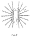
- all of the printing levers a are radially disposed with respect to said guide holes and have their movable ends positioned on an elliptical line, so as to minimize the curvatures of all of the printing wires.
- a projected distance l from the joining point c between the driven end of a printing wire b and the corresponding inner end of a printing lever a on the one hand to the printing end of the printing wire b on the other hand is shortened.
- the minimized curvature or deflection of the printing wires results in a reduced friction between the printing wires and the guide holes.
- the entire length of the printing wires b is also shortened, thus decreasing their inertia. Therefore, the known configuration serves to increase the velocity of the printing process.
- a plurality of cores are protruded over the surface of an annular magnetic plate 2.
- armatures 11 Disposed on the respective end surfaces of cores 1 vis-á-vis with each other are armatures 11 fixed to printing levers 10. While no printing is performed, magnetic fluxes from permanent magnets 3 secured to the surface of magnetic plate 2 act to hold armatures 11 by attraction against the resilient forces of plate springs 5. During printing, the attraction of armatures 11 is released when electromagnetic coils 4 wound on cores 11 are selectively energized by electric current to negate the permanent magnetic fluxes. Due to the resilient force of the plate springs 5, printing wires 12 connected to the radially inner ends of the printing levers 10 are then pushed through guide holes at the end of a nose portion 6, thus effecting the printing process.
- Fig. 4 is a plan view seen from the left side of Fig. 3 and illustrating on an exaggerated scale the positional relation between the printing levers 10 and the printing wires 12 according to one embodiment of the present invention.
- the reference numeral 7 denotes a guide plate provided with two parallel rows of guide holes 8.
- the guide plate 7 is fixed to the end of nose portion 6 as shown in Fig. 3.
- the guide holes 8 serve to guide the printing ends d of the printing wires 12 whose driven ends are fixed to the printing levers 10 as mentioned before.
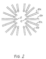
- the printing levers 10 are positioned around these guide holes and, except for printing levers 10A, extend radially with respect to the corresponding guide hole 8 so that their axes pass through the projected centers of corresponding guide holes 8.
- the inner ends of the printing levers 10 are disposed outwards to have a projected distance l from the guide holes 8.
- the printing levers are arranged at spacings ⁇ of, e.g. 0.2 mm, so that the printing wires 12 do not come into contact with each other.
- printing levers 10A corresponding to guide holes 8A provided at both ends of the parallel rows of guide holes are arranged in such a manner that their axial lines 10a are displaced inwards from the projected centers of the corresponding guide holes 8A. Furthermore, printing levers 10A are placed to keep at least spacings ⁇ between contiguous printing levers 10B.
- the two levers 10A on each side of the parallel rows are spaced apart by a distance defined by the two rows of guide holes 8. As in the case of the other printing levers 10, their inner ends are positioned at given distances l from the corresponding guide holes 8A.
- a group of printing levers 10 are disposed at spacings ⁇ of, e.g. 0.2 mm, corresponding to the cores 1 provided on the annular magnetic plate 2, so that printing wires fixed to the ends of respective printing levers do not come into contact with each other.
- the inner ends of the printing levers 10 are arranged in what may be called a zigzag fashion, as to be seen from Fig. 2.
- the inner ends of the printing levers 10F are disposed as close as possible to positions just above the respective guide holes 8.
- the inner ends of printing levers 10R are retracted with respect to those of printing levers 10F and disposed to approach positions just above the respective guide holes 8 to the greatest possible degree.
- printing levers 10F and 10R are alternately arranged.
- the numeral 9 denotes a spacer for supporting plate springs 5.
- the inner peripheral edge of spacer 9 (Fig. 1) is formed with rugged plate spring support parts 9a corresponding to the position of the individual inner ends of printing levers 10 in order to equalize the effective lengths L of levers 10 through plate springs 5, viz., the distances from the inner ends of levers 10 to the inner peripheral edge of spacer 9.
- Fig. 1 schematically illustrates this situation with the armatures 11 and the plate springs 5 being omitted.
- the fundamental constructions, including dimensions, etc., of armatures 11 and printing levers 10 are respectively the same and, hence, the effective lengths A (see Fig. 3) of the plate springs 5 become all equal.
- the inner ends of the printing levers 10F are near to positions just above the corresponding guide holes 8, the deflections of the corresponding printing wires 12 are nearly eliminated.
- the position of the inner ends of the printing levers 10F are spaced apart by e.g. 0.5 mm from positions just above the corresponding guide holes 8, thereby still minimizing the deflections of the printing wires 12 connected to printing levers 10R.
- the axial lines 10a of some printing levers 10 may not pass through the projected centers of the corresponding guide holes 8 and are not properly aligned with but intersect the plane of the printing wires 12. However, these deviations are remarkably small as compared with the effective length L of the printing levers 10, so that there is almost no influence from those deviations.
- the outwardly fan-shaped spaces between the radially disposed printing levers can be utilized as spatial portions in which the respective printing wires are placed. It is also feasible to concentrate the printing wires with high density at the center of the printing head without remarkably enhancing both, the processing accuracy of parts and the assembling accuracy thereof.
- the inner ends of the printing levers which protrude forward toward the center can be disposed as close as possible to positions just above the corresponding guide holes.
- the inner ends of the retracted printing levers are allowed to be placed still near to positions just above the corresponding guide holes.
- the printing levers used to drive those printing wires guided by the guide holes 8A at the end of the rows of guide holes are displaced from the projected centers of the guide holes, thus providing the necessary gaps between those printing levers and the adjacent levers.
- This arrangement permits to dispose the inner ends of these printing levers closest to positions just above the respective guide holes, still keeping the necessary clearance between the printing levers densely provided in the vicinity of the ends of the guide hole rows without considerably enhancing the accuracy with which the parts are processed and assembled. Also in this case, the deflections of the printing wires are minimized resulting in advantages already mentioned above.
- Fig. 6 is a schematic plan view of a wire dot printer showing an embodiment in accordance with the present invention. Desired figures and characters are printed on printing paper P arranged between platen 27 and ink ribbon 25 by impact dot head 20 mounted on carriage 26 which is supported movably in the printing column direction.
Landscapes
- Impact Printers (AREA)
Priority Applications (1)
| Application Number | Priority Date | Filing Date | Title |
|---|---|---|---|
| EP92118269A EP0530853B1 (de) | 1988-12-09 | 1989-07-25 | Punktmatrixdrucker mit Anschlagdruckkopf |
Applications Claiming Priority (4)
| Application Number | Priority Date | Filing Date | Title |
|---|---|---|---|
| JP311428/88 | 1988-12-09 | ||
| JP63311427A JP2789621B2 (ja) | 1988-12-09 | 1988-12-09 | ワイヤードットプリンタ用の印字ヘッド |
| JP31142888A JPH02155747A (ja) | 1988-12-09 | 1988-12-09 | ワイヤードットプリンタ用の印字ヘッド |
| JP311427/88 | 1988-12-09 |
Related Child Applications (1)
| Application Number | Title | Priority Date | Filing Date |
|---|---|---|---|
| EP92118269.7 Division-Into | 1992-10-26 |
Publications (3)
| Publication Number | Publication Date |
|---|---|
| EP0372162A2 true EP0372162A2 (de) | 1990-06-13 |
| EP0372162A3 EP0372162A3 (en) | 1990-09-12 |
| EP0372162B1 EP0372162B1 (de) | 1993-12-08 |
Family
ID=26566722
Family Applications (2)
| Application Number | Title | Priority Date | Filing Date |
|---|---|---|---|
| EP89113689A Expired - Lifetime EP0372162B1 (de) | 1988-12-09 | 1989-07-25 | Punktmatrixdrucker mit Anschlagdruckkopf |
| EP92118269A Expired - Lifetime EP0530853B1 (de) | 1988-12-09 | 1989-07-25 | Punktmatrixdrucker mit Anschlagdruckkopf |
Family Applications After (1)
| Application Number | Title | Priority Date | Filing Date |
|---|---|---|---|
| EP92118269A Expired - Lifetime EP0530853B1 (de) | 1988-12-09 | 1989-07-25 | Punktmatrixdrucker mit Anschlagdruckkopf |
Country Status (5)
| Country | Link |
|---|---|
| US (1) | US5083876A (de) |
| EP (2) | EP0372162B1 (de) |
| DE (2) | DE68927390T2 (de) |
| HK (2) | HK82695A (de) |
| SG (1) | SG47821A1 (de) |
Families Citing this family (1)
| Publication number | Priority date | Publication date | Assignee | Title |
|---|---|---|---|---|
| JP2938979B2 (ja) * | 1990-12-21 | 1999-08-25 | シチズン時計株式会社 | プリンタの印字ヘッド |
Family Cites Families (11)
| Publication number | Priority date | Publication date | Assignee | Title |
|---|---|---|---|---|
| CA1125661A (en) * | 1977-04-28 | 1982-06-15 | Noel F. Depew | Vibration dampening printing element guide means |
| US4225250A (en) * | 1978-10-10 | 1980-09-30 | Tally Corporation | Segmented-ring magnet print head |
| US4218150A (en) * | 1978-11-20 | 1980-08-19 | Vydec, Inc. | Matrix printer |
| JPS5826546U (ja) * | 1981-08-14 | 1983-02-19 | 東芝テック株式会社 | ドットプリンタヘッドのニ−ドル |
| JPS5829681A (ja) * | 1981-08-17 | 1983-02-21 | Fujitsu Ltd | 印字ヘッド |
| JPS58168581A (ja) * | 1982-03-31 | 1983-10-04 | Brother Ind Ltd | ドツトプリンタの印字ワイヤ駆動装置 |
| JPS5991070A (ja) * | 1982-11-16 | 1984-05-25 | Tokyo Electric Co Ltd | 釈放型ドツトプリンタヘツド |
| US4453840A (en) * | 1982-12-06 | 1984-06-12 | Hodne Ingard B | Actuator for a print wire |
| JPS615954A (ja) * | 1984-06-19 | 1986-01-11 | Nec Corp | ワイヤドツト式印字ヘツド |
| US4571102A (en) * | 1984-10-09 | 1986-02-18 | Epson Corporation | Ribbon mask device |
| US4669898A (en) * | 1985-12-23 | 1987-06-02 | Electronics Research And Service Organization | Dot matrix print head |
-
1989
- 1989-07-25 EP EP89113689A patent/EP0372162B1/de not_active Expired - Lifetime
- 1989-07-25 EP EP92118269A patent/EP0530853B1/de not_active Expired - Lifetime
- 1989-07-25 DE DE68927390T patent/DE68927390T2/de not_active Expired - Fee Related
- 1989-07-25 SG SG1996004568A patent/SG47821A1/en unknown
- 1989-07-25 DE DE89113689T patent/DE68911278T2/de not_active Expired - Fee Related
- 1989-09-06 US US07/403,436 patent/US5083876A/en not_active Expired - Lifetime
-
1995
- 1995-05-25 HK HK82695A patent/HK82695A/en not_active IP Right Cessation
-
1997
- 1997-06-26 HK HK114497A patent/HK114497A/en not_active IP Right Cessation
Also Published As
| Publication number | Publication date |
|---|---|
| EP0530853B1 (de) | 1996-10-23 |
| DE68911278T2 (de) | 1994-05-05 |
| HK82695A (en) | 1995-06-01 |
| EP0372162B1 (de) | 1993-12-08 |
| EP0530853A1 (de) | 1993-03-10 |
| DE68927390D1 (de) | 1996-11-28 |
| HK114497A (en) | 1997-08-29 |
| US5083876A (en) | 1992-01-28 |
| EP0372162A3 (en) | 1990-09-12 |
| DE68911278D1 (de) | 1994-01-20 |
| DE68927390T2 (de) | 1997-03-27 |
| SG47821A1 (en) | 1998-04-17 |
Similar Documents
| Publication | Publication Date | Title |
|---|---|---|
| US3994381A (en) | Wire matrix print head | |
| EP0425285B1 (de) | Punktdruckkopf für einen seriellen Drucker | |
| EP0372162B1 (de) | Punktmatrixdrucker mit Anschlagdruckkopf | |
| US4141661A (en) | Guide system for wire matrix printing | |
| GB2177778A (en) | Annular rolled metal member for use in a print head | |
| US4768892A (en) | Electromagnetic hammer actuator for impact printer | |
| US5219235A (en) | Dot line printer having improved yoke assembly | |
| EP0474254A1 (de) | Punktnadeldruckkopf | |
| JP2789621B2 (ja) | ワイヤードットプリンタ用の印字ヘッド | |
| JP2949503B2 (ja) | 印字ヘッド | |
| US5674015A (en) | Arrangement of actuators and tip ends in a wire dot print head | |
| JPH0717486Y2 (ja) | ワイヤドット印字ヘッド | |
| US5228386A (en) | Print hammer assembly for dot line printer | |
| JPH02155747A (ja) | ワイヤードットプリンタ用の印字ヘッド | |
| EP0267720A2 (de) | Flexible Drahtführung für Punktmatrixdrucker | |
| JPH058473A (ja) | インパクトドツトプリンタ | |
| EP0408316B1 (de) | Schlagpunktkopf für einen Drucker | |
| Zable et al. | An overview of impact printing | |
| JP2560681B2 (ja) | 印字モードを切換え可能なワイヤドットプリンタ | |
| JPS59220379A (ja) | シリアルドツトプリンタの印字ヘツド | |
| JPH03262648A (ja) | ワイヤードットプリンタ | |
| JPS62278057A (ja) | ドツトプリンタの印字ヘツド | |
| JPS59229359A (ja) | 印字ヘツド | |
| JPH01262147A (ja) | 両面印字ヘッド | |
| JPH0419151A (ja) | ワイヤードットプリントヘッド |
Legal Events
| Date | Code | Title | Description |
|---|---|---|---|
| PUAI | Public reference made under article 153(3) epc to a published international application that has entered the european phase |
Free format text: ORIGINAL CODE: 0009012 |
|
| AK | Designated contracting states |
Kind code of ref document: A2 Designated state(s): DE FR GB |
|
| PUAL | Search report despatched |
Free format text: ORIGINAL CODE: 0009013 |
|
| AK | Designated contracting states |
Kind code of ref document: A3 Designated state(s): DE FR GB |
|
| 17P | Request for examination filed |
Effective date: 19900917 |
|
| 17Q | First examination report despatched |
Effective date: 19920622 |
|
| GRAA | (expected) grant |
Free format text: ORIGINAL CODE: 0009210 |
|
| AK | Designated contracting states |
Kind code of ref document: B1 Designated state(s): DE FR GB |
|
| REF | Corresponds to: |
Ref document number: 68911278 Country of ref document: DE Date of ref document: 19940120 |
|
| ET | Fr: translation filed | ||
| PLBE | No opposition filed within time limit |
Free format text: ORIGINAL CODE: 0009261 |
|
| STAA | Information on the status of an ep patent application or granted ep patent |
Free format text: STATUS: NO OPPOSITION FILED WITHIN TIME LIMIT |
|
| 26N | No opposition filed | ||
| REG | Reference to a national code |
Ref country code: GB Ref legal event code: IF02 |
|
| PGFP | Annual fee paid to national office [announced via postgrant information from national office to epo] |
Ref country code: GB Payment date: 20060719 Year of fee payment: 18 Ref country code: FR Payment date: 20060719 Year of fee payment: 18 |
|
| PGFP | Annual fee paid to national office [announced via postgrant information from national office to epo] |
Ref country code: DE Payment date: 20060720 Year of fee payment: 18 |
|
| GBPC | Gb: european patent ceased through non-payment of renewal fee |
Effective date: 20070725 |
|
| PG25 | Lapsed in a contracting state [announced via postgrant information from national office to epo] |
Ref country code: DE Free format text: LAPSE BECAUSE OF NON-PAYMENT OF DUE FEES Effective date: 20080201 |
|
| PG25 | Lapsed in a contracting state [announced via postgrant information from national office to epo] |
Ref country code: GB Free format text: LAPSE BECAUSE OF NON-PAYMENT OF DUE FEES Effective date: 20070725 |
|
| REG | Reference to a national code |
Ref country code: FR Ref legal event code: ST Effective date: 20080331 |
|
| PG25 | Lapsed in a contracting state [announced via postgrant information from national office to epo] |
Ref country code: FR Free format text: LAPSE BECAUSE OF NON-PAYMENT OF DUE FEES Effective date: 20070731 |