EP0372467B1 - Elektronisches schwarzes Brett mit Bildanzeigefunktion - Google Patents
Elektronisches schwarzes Brett mit Bildanzeigefunktion Download PDFInfo
- Publication number
- EP0372467B1 EP0372467B1 EP89122373A EP89122373A EP0372467B1 EP 0372467 B1 EP0372467 B1 EP 0372467B1 EP 89122373 A EP89122373 A EP 89122373A EP 89122373 A EP89122373 A EP 89122373A EP 0372467 B1 EP0372467 B1 EP 0372467B1
- Authority
- EP
- European Patent Office
- Prior art keywords
- image
- paper
- recording medium
- toner
- flexible sheet
- Prior art date
- Legal status (The legal status is an assumption and is not a legal conclusion. Google has not performed a legal analysis and makes no representation as to the accuracy of the status listed.)
- Expired - Lifetime
Links
Images




Classifications
-
- G—PHYSICS
- G09—EDUCATION; CRYPTOGRAPHY; DISPLAY; ADVERTISING; SEALS
- G09G—ARRANGEMENTS OR CIRCUITS FOR CONTROL OF INDICATING DEVICES USING STATIC MEANS TO PRESENT VARIABLE INFORMATION
- G09G3/00—Control arrangements or circuits, of interest only in connection with visual indicators other than cathode-ray tubes
- G09G3/008—Control arrangements or circuits, of interest only in connection with visual indicators other than cathode-ray tubes forming an image on an image carrier by relative movement of a writing unit to the image carrier, e.g. on a photoconductive rotating belt, or on an electronic blackboard
-
- G—PHYSICS
- G03—PHOTOGRAPHY; CINEMATOGRAPHY; ANALOGOUS TECHNIQUES USING WAVES OTHER THAN OPTICAL WAVES; ELECTROGRAPHY; HOLOGRAPHY
- G03G—ELECTROGRAPHY; ELECTROPHOTOGRAPHY; MAGNETOGRAPHY
- G03G15/00—Apparatus for electrographic processes using a charge pattern
- G03G15/20—Apparatus for electrographic processes using a charge pattern for fixing, e.g. by using heat
- G03G15/2003—Apparatus for electrographic processes using a charge pattern for fixing, e.g. by using heat using heat
- G03G15/2007—Apparatus for electrographic processes using a charge pattern for fixing, e.g. by using heat using heat using radiant heat, e.g. infrared lamps, microwave heaters
- G03G15/201—Apparatus for electrographic processes using a charge pattern for fixing, e.g. by using heat using heat using radiant heat, e.g. infrared lamps, microwave heaters of high intensity and short duration, i.e. flash fusing
-
- G—PHYSICS
- G03—PHOTOGRAPHY; CINEMATOGRAPHY; ANALOGOUS TECHNIQUES USING WAVES OTHER THAN OPTICAL WAVES; ELECTROGRAPHY; HOLOGRAPHY
- G03G—ELECTROGRAPHY; ELECTROPHOTOGRAPHY; MAGNETOGRAPHY
- G03G15/00—Apparatus for electrographic processes using a charge pattern
- G03G15/22—Apparatus for electrographic processes using a charge pattern involving the combination of more than one step according to groups G03G13/02 - G03G13/20
- G03G15/221—Machines other than electrographic copiers, e.g. electrophotographic cameras, electrostatic typewriters
Definitions
- This invention relates to an electronic image display apparatus according to the preamble of claim 1, in which an electrostatic latent image is formed on a blackboard display member formed by a continuous flexible sheet by means of an electrostatic recording head and, more particularly, to a system in which the latent image is electrostatically recorded and converted into a visible image.
- An electronic image display apparatus of this type is known from JP-A-63 261 956.
- an electronic blackboard having a display function comprises an electronic recording medium 1 in the form of an endless flexible sheet arranged to be transported by a feed motor 2 and a drive roller 3.
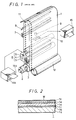
- the electronic recording medium 1 includes a substrate 1a composed of a sheet of polyethylene terephthalate having a thickness of 100 microns.
- An electrically conductive layer 1c having a thickness of about 50 microns is composed of a polymer such as polyurethane, and adheres to the substrate 1a by means of an adhesive layer 1b having a thickness of about 10 microns.
- the polymer constituting the electrically conductive layer 1c contains titanium dioxide or indium oxide, is white in color, and may be derived from a mixture of diisocyanate and polyethylene glycol.
- An ultraviolet light ray absorber is contained in the adhesive layer 1d.
- polyvinylidene fluoride is a substance that generally cannot be adherent by means of regular adhesives, so a special pressure-sensitive adhesive is used.
- a hard coat layer 1f is applied to the surface of the dielectric layer 1e, and the surface of the hard coat layer 1f may be used as a write surface W for the electrostatic recording medium 1.
- a commercial product known as "Tough Top” marketed by the Toray Corporation and made of a resin of a polysiloxane type can be used for the hard coat 1f. Consequently, damage to the write surface W can be prevented and letters or the like written on the write surface can be easily erased.
- a recording head 6 composed of a write electrode, a stylus electrode portion 4, and a control electrode portion 5, an AC charge remover 7, a cleaning blade 8, a charge coupled device (CCD) line sensor 10, a lens system 9, and a mirror 11 are all arranged in opposing relation to the endless electrostatic recording medium 1.
- a developer roller 12 is further provided for supplying toner.
- the electronic blackboard assembly is encased by a cover (not shown) having a window or aperture in a front portion thereof, with the electrostatic recording medium 1 being exposed through the window.
- a cover (not shown) having a window or aperture in a front portion thereof, with the electrostatic recording medium 1 being exposed through the window.
- an original document insertion slot 14a is provided in a lower portion of the front portion of the cover.
- a copy ejection slot 14b for printed paper.
- outlet slot 15 for printed paper.
- the cover is supported on rollers so that the electronic blackboard is easily transportable.
- this electronic blackboard information may be written on the write surface W of the electrostatic recording medium 1 with, for example, a felt pen or the like.
- the exposed portion of the electrostatic recording medium 1 is driven to a rear portion of the blackboard so that information written thereon can be read by the CCD line sensor 10 through the mirror 11 and the lens system 9.
- the visual information is converted into electrical signals by the CCD line sensor 10 and copied onto recording paper by, for example, xerography or a similar process, and the printed copy is discharged from the printed paper outlet slot 15.
- the document When it is desired to electrostatically display the image of an existing document on the electronic blackboard, the document is inserted through the document insertion slot 14a, and an electrostatic latent image is formed on the write surface W of the electrostatic recording medium 1 by the recording head 6.
- the latent image is developed by the toner supplied from the developer roller 12, and adheres to the electrostatic latent image on the write surface W as it passes the developer roller 12, resulting in a visible image (toner image).
- toner and ink marks written on the recording medium 1 with the felt pen are scraped away by the cleaning or doctor blade 8, and any charges or electrification on the write surface W of the recording medium 1 are removed by the AC charge remover 7.
- an object of the invention to provide an improved electronic blackboard including an electronic image display apparatus with the possibility to reproduce an image on the blackboard surface, i.e. the continuous flexible sheet on paper in larger reproduction, in particular in the original size as a fixed toner image.
- an electronic image display apparatus comprising a frame, sheet guides supported by said frame, a continuous flexible sheet supported for movement by said sheet guides, a recording head arranged to contact a surface of said flexible sheet for generating a latent image on said continuous flexible sheet, developing means for generating a visible image on said flexible sheet by supplying toner to said latent image formed on said flexible sheet by said recording head, the invention being characterized by signal processing means connected to said recording head to generate from image data fed thereto a normal image signal and a mirror image signal, each selectively supplied to said recording head, and by contact printing means for printing onto a paper said visible image formed by said toner on said flexible sheet, including means for causing said paper to directly contact said flexible sheet when said signal processing means supplies said mirror image signal to said recording head, thereby forming a normal toner image on said paper.
- Fig. 3 which shows an embodiment of the present invention
- like parts corresponding to those of the prior art blackboard shown in Fig. 1 are marked with the same reference numerals, and therefore need not be described in detail.
- an endless electrostatic recording medium 1 is arranged as a blackboard display member, which is driven by a drive motor 2 and a drive roller 3.
- An electrostatic recording head 6 composed of a multi-stylus electrode portion 4 surrounded by two control electrode portions 5, an AC charge removing roller 7, a cleaning assembly 8 composed of cleaning blades 8a1 and 8a2 and a cleaning roller brush 8b, a CCD line sensor 10 including a lens system 9 and a mirror 11 are all arranged in opposing relation to the electrostatic recording medium 1.
- a developer roller 12 is further provided for supplying toner from a toner compartment (not shown).
- a laterally extending flash lamp 16 is provided downstream of the developer roller 12 as a heating unit for fixing the image onto the recording medium 1.
- the flash lamp 16 has a length sufficient to extend over the full width of the electrostatic recording medium 1.
- a pressure roller 17 made of resilient material is arranged on the side of the recording medium 1 that is opposite the electrostatic recording head 6 to place the recording medium in pressure contact with the head 6, and guide rollers 18a1 and 18a2 are arranged to press the recording medium 1 against the cleaning blades 8a1 and 8a2. Further, guide rollers 19 and 20 are provided to guide the recording medium 1 for stable movement.
- a toner image of copy information is formed on a display surface of the electrostatic recording medium 1 in the same way as mentioned with respect to the conventional device shown in Fig. 1.
- an image transfer mechanism 21 which may utilize a transfer corotron, for example, is provided so that an image that is developed on the electrostatic recording medium 1 can be transferred to standard paper, thereby to preserve the image on a hard copy.
- a transfer corotron generates corona ions behind a paper to be printed and the charged toners on the writing surface are removed therefrom and attracted to the front side of the paper by the charge forces.
- the image transfer mechanism 21 comprises a bobbin 22 for holding a roll of paper P, pressure rollers 23a and 23b for pressing the paper P from the bobbin 22 against a developed surface of the electrostatic recording medium 1, the developer roller 12, a transfer corotron 24 located opposite the pressed portion of the paper P, a fixing flash lamp 25, paper feeding roller assembly 26, and a paper cutter 27.
- the roll paper P fed by the feeding rollers 26 from the bobbin 22 is pressed against the developed surface of the electrostatic recording medium 1 of the blackboard by the pressure rollers 23a and 23b.
- the transfer corotron 24, disposed immediately downstream of the pressure roller 23b, generates a charge behind the paper P, causing the charged toner image developed on the recording medium 1 to transfer onto the paper P.
- the toner image is transferred onto the paper P, it is permanently fixed onto the paper P with heat from the fixing flash lamp 25.
- the paper P having the toner image transferred thereon is driven by the feeding roller assembly 26 and cut by the paper cutter 27 at a predetermined location, resulting in a hard copy of the image having a size corresponding to the size of the image that was developed on the recording medium 1.
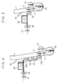
- Fig. 4 shows another embodiment of the transfer mechanism 21.
- a so-called peeling corotron 28 is provided downstream of the transfer corotron 24 in the region in which the paper P is still in intimate contact with the recording medium 1, but between the two pressure rollers 23a and 23b.
- the toner image is transfered by the transfer corotron 24 to the paper P, and it has been found that a good transfer is achieved when the distance between a wire of the transfer corotron 24 and the developed surface portion of the recording medium 1 is 10 mm and the voltage applied to the transfer corotron 24 is +4 kV.
- an AC voltage of 4 to 5 kV is applied to the peeling corotron 28 to weaken the adhesion between the paper P and the recording medium 1, and the toner transferred to the paper P is then fixed by heat generated from the fixing flash lamp 25.
- Toner remains on the recording medium 1 even after the toner image is transferred to the paper P. Therefore, it is scraped off by the cleaning blade 29 before the recording medium is presented once again on the display surface.
- Fig. 5 shows another embodiment of this transfer mechanism, in which without using any corotron a positive biasing voltage is applied to a single pressure roller 23, so that the toner image is transferred to the paper P while the paper P is being pressed to the recording medium 1 by the pressure roller 23.
- This embodiment can be constructed in a simpler manner than the preceding embodiment of Fig. 4.
- the pressure rollers 23a, 23b and 23, respectively, are movably arranged relative to the electrostatic recording medium 1, so that these rollers 23a, 23b and 23 can be separated from the recording medium 1 to prevent intimate contact between the paper P and the recording medium 1 when no image transfer is to be performed, thereby deferring to the inherent function of the blackboard, that is, to simply display an image on the display surface of the electrostatic recording medium 1.
- the electrostatic latent image is recorded from the original document onto the developing surface of the recording medium 1 in an inverted state with respect to the left and right or up and down directions, so that the toner image is developed as a mirror image.
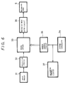
- Fig. 6 is a circuit block diagram of an example of a control circuit for controlling the operation of the electronic blackboard described above.
- the control circuit comprises an image reader 31 for reading a copy, a digitizing circuit 32 for digitizing the image signal supplied from the image reader 31 as a readout of copy information, a frame memory 33 for storing the digital image signal, a system controller 34, a memory control circuit 35 controlled by the system controller 34, a recording head drive circuit 36 to control the recording head 6 and adapted to be supplied with the image signal from the frame memory 33 under control of the memory control circuit 35, and a mechanism control circuit 37 for driving the blackboard and controlled by the system controller 34.
- the analog image signal from the CCD is converted to a digital signal for storage in the frame memory 33.
- the frame memory 33 supplies the image signal stored therein to the recording head drive circuit 36 in a forward sequential order under control of the memory control circuit 35 when a normal display instruction is given by the system controller 34.
- the recording head drive circuit 36 is connected to the respective stylus electrodes and the respective control electrodes of the recording head 6 to drive the latter by supplying drive signals to the respective electrodes of the head 6 according to the copy information supplied from the frame memory 33.
- the mechanism control circuit 37 for the blackboard is simultaneously actuated to drive the various mechanical portions of the blackboard other than the transfer mechanism 21, so that an electrostatic latent image can be recorded on the electrostatic recording medium 1 and the electronic blackboard can operate to display a toner image as described.
- the system controller 34 is operated manually to switch the operation mode to the image transfer mode. Upon this switching, a signal from the memory control circuit 35 instructs the frame memory 33 to read the copy information stored therein in a reverse order and to supply the information to the recording head drive circuit 36.
- the recording head 6 responds to the drive signal from the recording head drive circuit 36 to form a reversed or mirror electrostatic latent image of the original copy image onto the electrostatic recording medium. Under this condition, the paper P is brought into intimate contact with the portion of the recording medium where the latent image is formed, and a toner image of the original information is transferred to the paper P.
- FIG. 7 A first embodiment is shown in Fig. 7.
- respective lines of the information image data are read out and the bit positions of the information image data are reversed in the lateral direction. That is, assuming that one line includes 1600 bits, bit 0, bit 1, bit 2,..., bit 1599, the following replacement is performed:
- an information image A As shown in Fig. 8A, is formed on the recording medium 1 as a horizontal mirror image A , which is shown in Fig. 8B.
- a transfer image A is obtained on the paper P by transferring the mirror image A thereto, as shown in Fig. 8C.
- the information data are sequentially read from the bottom line of information to the top line of information, and the data read from the memory 33 are outputted sequentially, resulting in a mirror image B of an information image B on the recording medium 1, which is transferred to the paper P as a transfer image B which is the same as the information image B, as shown in Figs. 10A to 10C.
- the recording medium 1 is transported so that the image may be read by means of the CCD line sensor 10 disposed in the back side of the medium 1, as in the case of the above-mentioned conventional system, so that the image is converted to an electrical signal and written on copy paper through the head.
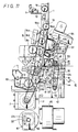
- Fig. 11 is a side view of an electronic blackboard according to the embodiment shown in Fig. 3, showing details of the transfer mechanism. Since other portions of this example are substantially the same as those described in relation to Fig. 3 and their operations have been described already, details thereof are omitted in the following description.
- the pressure rollers 23a and 23b are rotatably supported in parallel with each other by a support frame 41 and are mutually separated by a predetermined distance.
- the support frame 41 is movably mounted on a base plate 42 provided in a lower front portion of the blackboard assembly. More specifically, gang pieces or arms 45 and 46 respectively couple the support frame 41 to movable iron cores 43a and 44a of a pair of solenoids 43 and 44 provided on the base plate 42, so that the support frame 41 is moved with respect to the blackboard when the solenoids 43 and 44 are actuated.
- the gang pieces 45 and 46 are crossed and pivotally supported at their middle portions by a support pin 47 fixed to the base plate 42, and the length of the gang piece 46 extending toward the pressure roller 23a from the support pin 47 is selected to be larger than that length of the gang piece 45.
- the transfer corotron 24 is mounted on the support frame 41 at an intermediate position between the pressure rollers 23a and 23b.
- the fixing flash lamp 25, the feeding roller assembly 26, and the paper cutter 27 are respectively arranged downstream of the pressure roller 23a.
- a Xenon flash lamp may be used for the fixing flash lamp 25, which is housed in a lamp house 48.
- a reflection plate 49 is provided to reflect light from the lamp 25 to the copy paper to thereby quickly heat the copy paper and efficiently fix an image transferred to the paper P.
- the feeding roller assembly 26 is composed of a feeding roller 52 driven by a motor 50 through a belt 51 and a pinch roller 53 resiliently urged against the feeding roller 52 by a spring, in order to transport the copy paper P fed therebetween.
- the paper cutter 27 disposed adjacent the feeding roller assembly 26 is automatically actuated to cut the paper P after a predetermined length of the paper P has been fed.
- the transfer mechanism 21 thus constructed further includes a cleaning blade 54 which is provided upstream of the fixing flash lamp 16, which serves to fix the image on the recording medium 1.
- the cleaning blade 54 is mounted at the periphery of an opening of a toner receiving box 55, and a resilient receiving piece 56 is also mounted at the periphery of that opening opposite the cleaning blade 54.
- a base portion of the receiving box 55 is mounted on one end of an arm 59 that is rotatably supported at its middle portion on the base plate 42 by a support pin 58, the other end of the arm 59 being coupled to movable iron core 57a of a third solenoid 57, so that the arm 59 is rotated about the support pin 58 by action of the solenoid 57 and hence the cleaning blade 54 and the receiving piece 56 can be moved to make contact with or be separated from the surface of the electrostatic recording medium 1.
- the bobbin 22 of the paper P is rotatably supported by a bracket 60 to which a pressure element 61 is mounted.
- the pressure element 61 is in resilient contact with a shaft 22a of the bobbin 22 in order to prevent over-spooling.
- the motor 2 for driving the electrostatic recording medium 1 is a stepper motor coupled to the drive roller 3 through a belt 62.
- a toner supply box 63 is associated with the developer roller 12 to provide an adequate supply of toner.
- the electronic blackboard assembly shown in Figs. 11 further includes a copy reading scanner 64 and a cooling blower 65.
- the solenoids 43 and 44 are in an OFF position, as shown in Fig. 12, so that the movable iron cores 43a and 44a thereof are extended, and the gang pieces 45 and 46 respectively connected to the cores 43a and 44a are rotated around the pin 47 affixed to the support portion 42 in such a manner that gang piece 45 is rotated in the counterclockwise direction and gang piece 46 is rotated in the clockwise direction.
- the support frame 41 is thereby moved away from the recording medium 1 so that the pressure rollers 23a and 23b are separated from the recording medium 1.
- the core 57a thereof extends and the arm 59 connected thereto is rotated about the pin 58 in a counterclockwise direction.
- the cleaning blade 54 and the receiving piece 56 mounted on the receiving box 55 are thereby moved away from the recording medium 1.
- the transfer mechanism 21 When the transfer mechanism 21 is not in operation, a normal latent image is recorded by the recording head 6 on the write surface of the electrostatic recording medium 1, and the toner supplied from the developer roller 12 adheres to the electrostatic latent image, thus a visible normal image is displayed. Under such condition, the toner image is semi-permanently fixed by heat from the fixing flash lamp 16 as the image portion of the recording medium 1 travels past the lamp 16, so that scattering of the toner is prevented.
- toner T In the non-fixed state, as shown in Fig. 13A, the toner is simply residing on the surface of the recording medium 1, however, toner T is semi-permanently fixed onto the recording medium 1, as shown in Fig. 13B, by supplying energy to toner T, which energy may be about one third the energy necessary to permanently fix it.
- toner T is of a styrene acryl system
- the semi-permanent fixing thereof can be achieved by supplying energy of about 0.5 to 0.7 Joule/cm2.
- the transporting speed of the recording medium 1 and flashing interval of the flash lamp 16, and other parameters may be determined on the basis of this energy value.
- a portion of the electrostatic recording medium 1 on which the electrostatic latent image is formed is transported to the developer roller 12, from which an amount of suitably colored toner adheres to the write surface W of the recording medium according to an amount of charge thereon.
- a visible image corresponding to the original copy information is written and displayed on the electrostatic recording medium 1. Since toner particles of this toner image are melted together around the outermost portions thereof by the Xenon lamp 16 so that the particles are semi-permanently fixed to the recording medium, as shown in Fig. 13B, scattering of toner and contamination of clothes by the toner is prevented. Since the portions of the toner particles adjacent to the write surface W are not melted together in this semi-permanent state shown in Fig. 13B, they can be easily scraped away by the cleaning blade and even by a hand scraper, resulting in facilitated erasure and/or amendment of the toner image.
- the transfer mechanism 21 is actuated to place the paper P in intimate contact with the electrostatic recording medium 1 by means of the pressure rollers 23a and 23b. More specifically, when the transfer mechanism 21 is actuated, the movable cores 43a and 44a of the solenoids 43 and 44 are retracted, rotating the gang pieces 45 and 46 in clockwise and counterclockwise directions, respectively, to thereby move the support frame 41, and hence the pressure rollers 23a and 23b, toward the recording medium 1 and press the paper P against the recording medium 1.
- the movable core 57a thereof is retracted so that the arm 59 is rotated in the clockwise direction to move the cleaning blade 54 and the receiving piece 56 on the receiving box 55 toward the recording medium 1 until the top ends of each are in contact with the recording medium.
- the latent image is recorded on the recording medium 1 by the recording head 6 as a mirror image of the original copy.
- the mirror image is then developed by the toner supplied from the developer roller 12.
- This developed mirror image is transferred by the corotron 24 of the transfer mechanism 21 to the paper P while the portion of the paper which is in intimate contact with the recording medium 1 is moved together with the recording medium by the feeding member 26.
- the transferred image on the paper is a normal image of the copy and is permanently fixed thereon by heat from the fixing flash lamp 25.
- the paper P having the normal image thereon is further transported by the feeding roller assembly 26 of the transfer mechanism 21, particularly, the feed roller 52 driven by the motor 50 and the pinch roller 53 and, after a predetermined length thereof is fed, the paper is cut by the paper cutter 27, resulting in a hard copy of, for example, A1 size.
- an image transfer function is added to an electronic blackboard already having a copy information display function, it becomes possible to transfer an image of a size corresponding to that of the original copy information, to store an image on a large size paper, to form a large size poster from an A4 size copy and/or to store a hard copy obtained by amending and/or correcting an image displayed on a display surface of the blackboard. Further, a number of large-sized copies can be obtained.
Landscapes
- Physics & Mathematics (AREA)
- General Physics & Mathematics (AREA)
- Engineering & Computer Science (AREA)
- Computer Hardware Design (AREA)
- Theoretical Computer Science (AREA)
- Drawing Aids And Blackboards (AREA)
- Combination Of More Than One Step In Electrophotography (AREA)
Claims (3)
- Elektronische Bildanzeigevorrichtung, mit
einem Rahmen;
durch den Rahmen aufgenommene Bogenführungen (18a₁, 18a₂, 19, 20);
einem durch die Bogenführungen beweglich gehaltenen flexiblen Endlosbogen (1);
einem Aufnahmekopf (6), der die Oberfläche des flexiblen Bogens berührt, um ein latentes Bild auf dem flexiblen Endlosbogen zu erzeugen;
einem Entwickler (12) zur Erzeugung eines sichtbaren Bildes auf dem flexiblen Bogen durch Aufbringen von Toner auf dem latenten Bild, das von dem Aufnahmekopf auf dem flexiblen Bogen gebildet wurde, gekennzeichnet durch
eine Signalverarbeitungseinrichtung (31 bis 37), die an den Aufnahmekopf (6) angeschlossen ist, um von den an sie gelieferten Bilddaten ein normales Bildsignal und ein Spiegelbildsignal zu erzeugen, wobei jedes einzeln an den Aufnahmekopf (6) übertragen wird; und durch
eine Druckeinrichtung (23a, 23b, 24 bis 27), um das durch den Toner auf dem flexiblen Bogen gebildete, sichtbare Bild auf ein Papier (P) zu drucken, mit einer Einrichtung (23a, 23b), um das Papier (P) in direkten Kontakt mit dem flexiblen Bogen (1) zu bringen, wenn die Signalverarbeitungseinrichtung das Spiegelbildsignal an den Aufnahmekopf (6) überträgt, wordurch ein normales Toner-Bild auf dem Papier (P) gebildet wird. - Vorrichtung nach Anspruch 1, gekennzeichnet durch einen Fixierer (25) zum Fixieren des Toners auf dem Papier (P), wenn die Signalverarbeitungseinrichtung das Spiegelbildsignal liefert, wodurch das Toner-Bild auf dem Papier fixiert wird.
- Vorrichtung nach Anspruch 1 oder 2, gekennzeichnet durch eine Transfer-Corona (24) zur Übertragung des Toner-Bilds auf das Papier (P) und eine in Papiertransportrichtung stromab von der Transfer-Corona (24) angeordnete Ablöse-Corona (28), die mit einer Wechselspannung versorgt wird, um die Adhäsion zwischen dem Papier (P) und dem Aufzeichnungsmedium (1) abzuschwächen.
Applications Claiming Priority (4)
| Application Number | Priority Date | Filing Date | Title |
|---|---|---|---|
| JP63310669A JP2653143B2 (ja) | 1988-12-08 | 1988-12-08 | 電子黒板 |
| JP310669/88 | 1988-12-08 | ||
| JP197797/89 | 1989-07-29 | ||
| JP19779789A JPH0361979A (ja) | 1989-07-29 | 1989-07-29 | 電子黒板 |
Publications (3)
| Publication Number | Publication Date |
|---|---|
| EP0372467A2 EP0372467A2 (de) | 1990-06-13 |
| EP0372467A3 EP0372467A3 (en) | 1990-09-26 |
| EP0372467B1 true EP0372467B1 (de) | 1994-03-02 |
Family
ID=26510573
Family Applications (1)
| Application Number | Title | Priority Date | Filing Date |
|---|---|---|---|
| EP89122373A Expired - Lifetime EP0372467B1 (de) | 1988-12-08 | 1989-12-05 | Elektronisches schwarzes Brett mit Bildanzeigefunktion |
Country Status (3)
| Country | Link |
|---|---|
| US (1) | US4953031A (de) |
| EP (1) | EP0372467B1 (de) |
| DE (1) | DE68913451T2 (de) |
Families Citing this family (5)
| Publication number | Priority date | Publication date | Assignee | Title |
|---|---|---|---|---|
| JPH03170979A (ja) * | 1989-11-30 | 1991-07-24 | Toshiba Corp | 画像形成装置 |
| JPH056088A (ja) * | 1991-02-15 | 1993-01-14 | Toshiba Corp | 静電記録装置 |
| US6319201B1 (en) * | 1997-10-15 | 2001-11-20 | Peter J. Wilk | Imaging device and associated method |
| JP3513451B2 (ja) | 1999-02-26 | 2004-03-31 | キヤノン株式会社 | 画像表示装置および画像消去方法 |
| CN106739704B (zh) * | 2017-01-21 | 2018-01-02 | 河北工业大学 | 一种智能黑板 |
Family Cites Families (2)
| Publication number | Priority date | Publication date | Assignee | Title |
|---|---|---|---|---|
| JPS58126564A (ja) * | 1982-01-25 | 1983-07-28 | Canon Inc | 表示兼プリント装置 |
| JPS6240862A (ja) * | 1985-08-19 | 1987-02-21 | Canon Inc | 電子表示記録装置 |
-
1989
- 1989-12-05 EP EP89122373A patent/EP0372467B1/de not_active Expired - Lifetime
- 1989-12-05 DE DE68913451T patent/DE68913451T2/de not_active Expired - Fee Related
- 1989-12-07 US US07/447,078 patent/US4953031A/en not_active Expired - Fee Related
Also Published As
| Publication number | Publication date |
|---|---|
| EP0372467A2 (de) | 1990-06-13 |
| EP0372467A3 (en) | 1990-09-26 |
| DE68913451T2 (de) | 1994-09-01 |
| DE68913451D1 (de) | 1994-04-07 |
| US4953031A (en) | 1990-08-28 |
Similar Documents
| Publication | Publication Date | Title |
|---|---|---|
| CA1075758A (en) | Dual mode electrophotographic apparatus having dual function printing beam | |
| JP2848547B2 (ja) | 画像形成装置用ローラ及びこれを用いた画像形成装置 | |
| US4825245A (en) | Duplex printing module for an electrographic printer | |
| US4758862A (en) | Electrographic printer/copier with duplex printing | |
| US5048983A (en) | Electrographic typewriter | |
| EP0372467B1 (de) | Elektronisches schwarzes Brett mit Bildanzeigefunktion | |
| US6049345A (en) | Image forming apparatus selectively charging toner using doctor blade | |
| US4774593A (en) | Image forming apparatus | |
| US5983041A (en) | Image recording apparatus having a neutralizing device | |
| JPH0358074A (ja) | クリーニングシート | |
| US5506662A (en) | Image forming apparatus including an image bearing member and an erasing device for erasing a portion of an image from the image bearing member | |
| JPH01280783A (ja) | 画像形成装置 | |
| JPH09204083A (ja) | 画像記録装置 | |
| JPS63267980A (ja) | 画像形成装置 | |
| JPH03273269A (ja) | 画像形成装置 | |
| JPH07129035A (ja) | 画像形成装置並びにこの画像形成装置の制御方法 | |
| US7489890B2 (en) | Color image forming apparatus with differing toner time constants | |
| JPH0361979A (ja) | 電子黒板 | |
| JP2653143B2 (ja) | 電子黒板 | |
| JP3316786B2 (ja) | 電子写真装置 | |
| JPH06270497A (ja) | 画像形成装置 | |
| JPS6217780A (ja) | 像形成装置 | |
| JPH0815918A (ja) | 画像形成装置ならびに画像形成方法 | |
| JPH03129375A (ja) | 電子黒板 | |
| JPS63271368A (ja) | 画像形成装置 |
Legal Events
| Date | Code | Title | Description |
|---|---|---|---|
| PUAI | Public reference made under article 153(3) epc to a published international application that has entered the european phase |
Free format text: ORIGINAL CODE: 0009012 |
|
| AK | Designated contracting states |
Kind code of ref document: A2 Designated state(s): DE FR GB |
|
| PUAL | Search report despatched |
Free format text: ORIGINAL CODE: 0009013 |
|
| RHK1 | Main classification (correction) |
Ipc: G03G 15/22 |
|
| AK | Designated contracting states |
Kind code of ref document: A3 Designated state(s): DE FR GB |
|
| 17P | Request for examination filed |
Effective date: 19901220 |
|
| 17Q | First examination report despatched |
Effective date: 19920812 |
|
| GRAA | (expected) grant |
Free format text: ORIGINAL CODE: 0009210 |
|
| AK | Designated contracting states |
Kind code of ref document: B1 Designated state(s): DE FR GB |
|
| REF | Corresponds to: |
Ref document number: 68913451 Country of ref document: DE Date of ref document: 19940407 |
|
| ET | Fr: translation filed | ||
| PLBE | No opposition filed within time limit |
Free format text: ORIGINAL CODE: 0009261 |
|
| STAA | Information on the status of an ep patent application or granted ep patent |
Free format text: STATUS: NO OPPOSITION FILED WITHIN TIME LIMIT |
|
| 26N | No opposition filed | ||
| PGFP | Annual fee paid to national office [announced via postgrant information from national office to epo] |
Ref country code: GB Payment date: 20011205 Year of fee payment: 13 |
|
| PGFP | Annual fee paid to national office [announced via postgrant information from national office to epo] |
Ref country code: FR Payment date: 20011212 Year of fee payment: 13 |
|
| PGFP | Annual fee paid to national office [announced via postgrant information from national office to epo] |
Ref country code: DE Payment date: 20011217 Year of fee payment: 13 |
|
| REG | Reference to a national code |
Ref country code: GB Ref legal event code: IF02 |
|
| PG25 | Lapsed in a contracting state [announced via postgrant information from national office to epo] |
Ref country code: GB Free format text: LAPSE BECAUSE OF NON-PAYMENT OF DUE FEES Effective date: 20021205 |
|
| PG25 | Lapsed in a contracting state [announced via postgrant information from national office to epo] |
Ref country code: DE Free format text: LAPSE BECAUSE OF NON-PAYMENT OF DUE FEES Effective date: 20030701 |
|
| GBPC | Gb: european patent ceased through non-payment of renewal fee | ||
| PG25 | Lapsed in a contracting state [announced via postgrant information from national office to epo] |
Ref country code: FR Free format text: LAPSE BECAUSE OF NON-PAYMENT OF DUE FEES Effective date: 20030901 |
|
| REG | Reference to a national code |
Ref country code: FR Ref legal event code: ST |