EP0372806B1 - Radbremsblock - Google Patents
Radbremsblock Download PDFInfo
- Publication number
- EP0372806B1 EP0372806B1 EP89312395A EP89312395A EP0372806B1 EP 0372806 B1 EP0372806 B1 EP 0372806B1 EP 89312395 A EP89312395 A EP 89312395A EP 89312395 A EP89312395 A EP 89312395A EP 0372806 B1 EP0372806 B1 EP 0372806B1
- Authority
- EP
- European Patent Office
- Prior art keywords
- wheel chock
- wheel
- chock
- wall
- transverse
- Prior art date
- Legal status (The legal status is an assumption and is not a legal conclusion. Google has not performed a legal analysis and makes no representation as to the accuracy of the status listed.)
- Expired - Lifetime
Links
- 230000000452 restraining effect Effects 0.000 claims description 11
- 238000010137 moulding (plastic) Methods 0.000 claims description 4
- 229910052782 aluminium Inorganic materials 0.000 claims description 3
- XAGFODPZIPBFFR-UHFFFAOYSA-N aluminium Chemical compound [Al] XAGFODPZIPBFFR-UHFFFAOYSA-N 0.000 claims description 3
- 238000005266 casting Methods 0.000 claims description 3
- 239000004411 aluminium Substances 0.000 claims 1
- 229910000831 Steel Inorganic materials 0.000 description 4
- 229910052751 metal Inorganic materials 0.000 description 4
- 239000002184 metal Substances 0.000 description 4
- 239000010959 steel Substances 0.000 description 4
- 229920003023 plastic Polymers 0.000 description 3
- 239000004033 plastic Substances 0.000 description 3
- 239000004677 Nylon Substances 0.000 description 2
- 229920000443 Xenoy Polymers 0.000 description 2
- 230000000694 effects Effects 0.000 description 2
- 238000009434 installation Methods 0.000 description 2
- 239000000463 material Substances 0.000 description 2
- 238000000034 method Methods 0.000 description 2
- 229920001778 nylon Polymers 0.000 description 2
- 230000000717 retained effect Effects 0.000 description 2
- 238000003860 storage Methods 0.000 description 2
- 229910000639 Spring steel Inorganic materials 0.000 description 1
- 230000002159 abnormal effect Effects 0.000 description 1
- 238000005299 abrasion Methods 0.000 description 1
- 238000013459 approach Methods 0.000 description 1
- 238000010276 construction Methods 0.000 description 1
- 238000006073 displacement reaction Methods 0.000 description 1
- 238000009826 distribution Methods 0.000 description 1
- 238000011900 installation process Methods 0.000 description 1
- 238000004519 manufacturing process Methods 0.000 description 1
- 238000000465 moulding Methods 0.000 description 1
- 239000002245 particle Substances 0.000 description 1
- 239000000725 suspension Substances 0.000 description 1
- 238000003466 welding Methods 0.000 description 1
- 238000004804 winding Methods 0.000 description 1
Images

Classifications
-
- B—PERFORMING OPERATIONS; TRANSPORTING
- B65—CONVEYING; PACKING; STORING; HANDLING THIN OR FILAMENTARY MATERIAL
- B65D—CONTAINERS FOR STORAGE OR TRANSPORT OF ARTICLES OR MATERIALS, e.g. BAGS, BARRELS, BOTTLES, BOXES, CANS, CARTONS, CRATES, DRUMS, JARS, TANKS, HOPPERS, FORWARDING CONTAINERS; ACCESSORIES, CLOSURES, OR FITTINGS THEREFOR; PACKAGING ELEMENTS; PACKAGES
- B65D47/00—Closures with filling and discharging, or with discharging, devices
-
- B—PERFORMING OPERATIONS; TRANSPORTING
- B60—VEHICLES IN GENERAL
- B60P—VEHICLES ADAPTED FOR LOAD TRANSPORTATION OR TO TRANSPORT, TO CARRY, OR TO COMPRISE SPECIAL LOADS OR OBJECTS
- B60P3/00—Vehicles adapted to transport, to carry or to comprise special loads or objects
- B60P3/06—Vehicles adapted to transport, to carry or to comprise special loads or objects for carrying vehicles
- B60P3/07—Vehicles adapted to transport, to carry or to comprise special loads or objects for carrying vehicles for carrying road vehicles
- B60P3/073—Vehicle retainers
- B60P3/075—Vehicle retainers for wheels, hubs, or axle shafts
- B60P3/077—Wheel cradles, chocks, or wells
-
- B—PERFORMING OPERATIONS; TRANSPORTING
- B61—RAILWAYS
- B61D—BODY DETAILS OR KINDS OF RAILWAY VEHICLES
- B61D45/00—Means or devices for securing or supporting the cargo, including protection against shocks
- B61D45/001—Devices for fixing to walls or floors
Definitions
- This invention concerns wheel chocks used to secure motor vehicles on the decks of transporters, especially railway cars.
- US-4668140 describes a wheel chock which consists of an elongate monolithic body; a pair of pins at one end to secure the body into an open topped box section rail mounted on the transport vehicle; and a support, pivotally mounted at the other end of the body to support the body in a position to engage a surface with a wheel.
- the object of this invention is to provide a practical wheel chock for use in association with a standard mounting rail of the kind mentioned above which eliminates major disadvantages of prior designs and which, we believe, satisfies well all of the essential requirements for this type of apparatus.
- a wheel chock for releasable attachment to an elongate restraining element affixed to a vehicle transporter and having a pair of walls, at least one of which contains a longitudinal series of uniformly spaced and sized holes
- the wheel chock comprising an elongate monolithic body formed with a side wall providing a portion which in use engages a wheel, a pair of locking pins fixed to the body and arranged to engage in respective holes in the restraining element when the body is placed on the restraining element from above and moved longitudinally, characterised in that the restraining element is received into a laterally extending recess formed in the body and bounded at one side by a transverse wall, the recess containing an unobstructed space wider than the restraining element but the surfaces of the body defining the recess being arranged to constrain the degree of tilt of the body in any direction so that at least one of the
- the main component of the new chock is the monolithic body defined by an aluminum casting or a synthetic plastic molding.
- This type of construction is sturdy, yet lightweight, so it can satisfy structural requirement and at the same time make use of the chock less tiring to the workers who load and unload the motor vehicles.
- the dimensions of a cast or moulded body may be easily controlled and selected to take full account of the manufacturing tolerances applicable to the mounting rail, a good and proper fit of the chock on the rail is guaranteed.
- the chock body is preferably an open bottom structure having a central ridge wall flanked by a pair of symmetrical downwardly and outwardly sloping wheel-engaging side wall portions. This gives the chock a universal character, i.e., it may be used either in front of or behind a vehicle wheel.
- the chock is secured by simply placing the chock so that the rail is received in the recess and sliding longitudinally to locate the pins in the holes.
- a manually operable latching member This member is mounted on the body for movement between a latching position, wherein it is positioned in the recess along one upright wall of the rail and coacts with the bounding recess wall to capture the rail sufficiently to prevent lateral withdrawal of the pins from the associated rail holes, and an unlatching position, in which it permits such withdrawal.
- the latching member is equipped with a manually releasable locking element which is effective automatically upon movement of the latching member to latching position to positively hold the member in that position.
- the locking element, and a manual actuator for the latching member are accessible at the outboard end of the chock. Therefore, mounting and dismounting of the chock can be effected easily and without the necessity for a worker to reach beneath the motor vehicle.
- the preferred chock incorporates a reeling shaft on which an end strap of such a harness is wound, and which is provided with a pawl and ratchet locking mechanism for holding the harness in taut condition.
- One end of the shaft is exposed at the outboard end of the chock body, and the pawl has a manually operated release element which also projects through that body end.
- the exposed pawl release element could be damaged or inadvertently actuated by a careless workman, so it is desirable to provide it with a guard.
- this guarding function is performed by the manual actuator of the latching member.
- the reeling shaft extends longitudinally through the chock body in a central region thereof, and the portion of the shaft which receives the harness strap underlies a relatively large window opening in the ridge wall of the body.
- the shaft is displaced from the center of the body, the eccentricity being such that the strap is positioned approximately in the center of the body in the region where it passes onto the shaft.
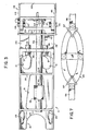
- the main component of the new chock is a monolithic body 11, which may be an aluminum casting but preferably is a synthetic plastic molding made from a material possessing good impact strength over the range of temperatures encountered by railroads. Suitable plastics are XENOY DX 5720 marketed by General Electric Company, and NYRIM 1000 marketed by DSM RIM Nylon, Inc.
- Body 11 has an open bottom, and a top defined by a central ridge wall 12 including a domed portion 12a adjoining transverse wall 13 at the outboard end of the body, a portion 12b located at the opposite end of the body and containing an opening 14, and an intermediate portion 12c which is taken up almost entirely by a large window opening 15.
- the ridge wall is flanked by a pair of side walls, each of which comprises a wheel-engaging surface 16 or 17 which slopes downward at an angle of about 55°-60° with respect to the horizontal and joins a depending surface 18 or 19.
- Surfaces 16 and 17 may be planar, but, as illustrated, each is curved on a large radius of about 11 ⁇ .
- Surfaces 18 and 19 are flat, and, except for a small draft angle of 10 required for molding, they are vertical.
- the side walls are symmetrical about the central, longitudinal vertical plane of body 11, which gives the chock a universal character, i.e., it may be positioned either in front of or behind a vehicle wheel.
- Each of the surfaces 16 and 17 contains a pair of openings 21 and 22 near its outboard end defining hand grips which enable the chock to be easily carried and manipulated by the workmen.
- Each surface also contains a keyhole shaped opening 23 near its inboard end so that the chock may be hung from a headed pin fastened to the side screen of the railway car. This feature obviates the metal storage boxes previously provided for chock storage.
- body 11 The side walls of body 11 are connected with each other and with the ridge wall by three transverse webs 24, 25 and 26, each of which extends over the entire cross section of the body at the station at which it is located. Since, as will be related, web 26 carries the locking pins which connect the chock to the mounting rail of the railway car, it is made thicker than the other webs.
- Body 11 also includes a fourth transverse web 27, this one extending over only the upper portion of the cross section of the body and being joined to web 26 by a pair of horizontal shelf-like webs 28 and 29 running along the side walls.
- the chock body is spanned by a transverse recess 31 which opens through vertical side surfaces 18 and 19 and is adapted to receive the standard hat section mounting rail 32 which extends lengthwise of, and is welded to, the deck 33 of the railway car.
- This recess 31 is bounded at the top by horizontal webs 28 and 29 and at the inboard side by transverse web 26.
- the bottom of that portion of body 11 extending inboard from recess 31 is elevated a distance X of approximately 3/8 ⁇ above the bottom of the wall 13.
- This spacing provides clearance for the inboard flange 34 of rail 32 and also allows the chock to assume a substantially horizontal orientation when deck 33 is crowned, as it sometimes is.
- the bottom edges of side wall surfaces 18 and 19 outboard of recess 31 are cut back as shown at 35. This measure provides clearance for the latching member described later.
- the chock may be fixed to rail 32 by a pair of cylindrical steel locking pins 36 projecting into recess 31 from web 26. These pins have threaded shanks which pass through bores formed in web 26 and are secured by self-locking nuts 37. The pins contain small cross bores 38 so they can be held by an awl or similar implement while the nuts are tightened.
- Each of the upright walls 39 of rail 32 contains a longitudinal series of 1 ⁇ diameter holes 41 located on 1 1/2 ⁇ centers, and locking pins 36 are sized and spaced to fit into alternate holes of this series. Typically, the pins have a diameter of 3/4 ⁇ and are installed with a center-to-center spacing of 2 3/4 ⁇ .
- the pins 36 extend about 1/2 ⁇ into recess 31, and the width of this recess is selected to afford an unobstructed or free space about 1/16 ⁇ wider than rail 32 (at maximum tolerance).
- the chock may be installed by lowering it onto the rail and then shifting it laterally to engage pins 36 in the holes 41.
- the height of recess 31 is about 1/16 ⁇ greater than the maximum permitted height of rail 32, so horizontal webs 28 and 29 are close to, but do not rest on, the rail when the chock is mounted in place.
- the chock may, and in service does, tilt in both the horizontal and vertical planes relatively to the rail, the close fit between rail 32 and recess 31 is selected to insure that the contact between the margins of the recess and the rail limits such movement and insures that one of the pins 26 always remains engaged in its associated hole 41. This guarantees that the chock will be effective to hold the vehicle even if the workers fail to latch it in place on the rail.
- the chock includes a latching mechanism which positively prevents withdrawal of either of the pins 36 from hole 41.
- This mechanism comprises a four-sided frame 42 made from a steel bar of rectanular cross seciton which is bent to U-shape and is welded at its free ends to a similar straight bar 43.
- the sides 44 and 45 of frame 42 are jounaled on headed pivot pins 46 which pass through openings in body surfaces 18 and 19 and are retained by cotter pins 47; therefore, frame 42 is free to swing in a vertical plane about the outboard end of body 11.
- bar 43 In the latching position of frame 42, which is illustrated in Fig. 1, bar 43 is positioned along and close to the outboard upright wall 39 of rail 32.
- the distance between bar 43 and transverse web 26 is approximately 1/16 ⁇ greater than the maximum width of rail 32; therefore, lateral movement of the chock is limited sufficiently to preclude withdrawal of pins 36 from holes 4I.
- the latch is released by grasping frame side 48, which serves as a handle, and swinging frame 42 counterclockwise (as viewed in Fig. 1) to a substantially vertical, unlatching position wherein bar 43 is outside recess 31 and in abutment with side wall portions 35. Sufficient clearance to avoid interference between the latch and the outboard flange of rail 32 during this movement is afforded by making bar 43 narrower than the rest of the frame, locating that bar flush with the bottom of the frame, and beveling the top corners of sides 44 and 45, all as shown in Fig. 1.
- Lock 49 is formed with a pocket 51 sized to receive frame side 44 and having a wall 52 which coacts with the upper margin of side 44 to positively hold frame 42 in latching position.
- the lock includes an integral nose or protruding release portion 53 which may be manually pressed to flex the lock outward about its mounting bolt 54. This action removes wall 52 from the path of travel of frame side 44, thereby permitting the frame to be pivoted toward unlatching position.
- Lock 49 is so positioned that, in the unlatching position of frame 42, it partially overlaps side 44 and bears against its outer face.
- the lock does not positively hold the frame 42 in the unlatching position, but acts merely as a friction grip which retards movement of the frame from that position.
- workers may activate the latch simply by pulling handle side 48 down.
- lock 49 automatically snaps into locking position to capture side 44 as the frame 42 is pivoted into latching position.
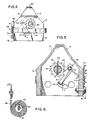
- a typical commercial harness depicted in Fig. 7, comprises five strips of nylon webbing, three of which are stitched together to form a central wheel-engaging portion 55, and the remaining two defining end straps 56 which are attached to portion 55 by steel D-rings 57. Both end straps may be permanently attached to the D-rings, or one may be stitched in place and the other provided with a hook (See Fig. 6) which allows removable attachment.
- the preferred chock includes mechanism for attaching the free end of a strap 56 and tensioning the harness.
- That mechanism includes a tubular steel reeling shaft 58 mounted for rotation in aligned bores formed in transverse webs 24-27 and equipped with a ratchet wheel 59 at its outboard end.
- Ratchet wheel 59 which coacts with end wall 13, and a cotter pin 61, which coacts with transverse web 25, hold shaft 58 against axial displacement.
- the portion of shaft 58 underlying body window 15 contains a pair of diametrically opposed slots 62 (see Fig. 6) sized to receive strap 56.
- the strap may be affixed to the shaft by threading its free end through both of the slots 62, folding the end over and attaching it to the main body of the strap, as by a staple 63, and then pulling the strap to draw the folded end into the interior of the shaft.
- the angle at which strap 56 approaches body 11 is not a constant, but varies with the diameter of the vehicle wheel, and also depends upon whether the chock is positioned fore or aft of the wheel. This angle variation should be taken into account in the design of the chock in order to minimize rubbing of the strap on the margins of window opening 15.
- the risk of rubbing is reduced by the expedients of locating shaft 58 at a relatively high elevation within body 11, and offsetting the shaft axis slightly (e.g. 1/4 ⁇ ) from the center, longitudinal, vertical plane of the body.
- Ratchet wheel 59 has an integral stub shaft which projects into the outboard end of tubular shaft 58 and is held there by cotter pin 64, and an oppositely directed, shorter stub shaft which is journaled in a bore extending through end wall 13.
- the end of the last mentioned stub shaft is flush with the outer surface of wall 13 and contains a square socket 65 for receiving the 1/2 ⁇ drive of a standard ratchet wrench.
- the ratchet wheel 59 coacts with a pawl 66 formed on a lever 67 pivotally mounted at one end on a bolt 68 fixed in wall 13. At its opposite end, lever 67 is bent to define a release arm 69 which projects from body 11 through an arcuate opening 71 formed in wall 13.
- a wire spring 72 trained about bolt 68 and formed with curved ends which bear against side wall 18 and arm 69, respectively, biases pawl 66 into engagement with the teeth on wheel 59.
- shaft 58 may be rotated freely in the counterclockwise direction, as viewed in Fig. 4, to reel in strap 56 and tension the harness, but retrograde motion is selectively prevented by the pawl and ratchet mechanism.
- the release arm 69 is within the confines of frame 42 and is positioned at approximately the elevation of handle 48 when the frame is in latching position. As a result, the frame, and especially handle 48, serves as a guard which reduces the risk that a careless worker will inadvertently step on arm 69 and either break it or release the pawl.
- body 11 be a synthetic plastic molding.
- the chock has a surprisingly light weight.
- an acceptable version of the illustrated chock 18 ⁇ long, 5 1/2 ⁇ wide and 6 1/8 ⁇ high and made of XENOY DX5720, weighs only about 5 1/2 pounds, including all metal hardware and an end strap 56.
- this form of body avoids the built in stresses which can be present in metal chocks, especially in those fabricated by welding.
- the plastic chock is less likely to cause abrasion damage to vehicle bodies when it is bumped against them as a result of careless handling during vehicle-loading andunloading operations.
- the plastic chock sheds ice more readily, and it causes less wear on the vehicle tires and harness straps which rub against it during service. Finally, any wearing of the chock body generates only relatively inert, nonrusting material particles which will not damage painted vehicle surfaces on which they may deposit.
- lockin9 pins 36, the reeling shaft 58 and the pawl and ratchet mechanism 59, 67, 72 in the preferred embodiment are located within the confines of, and effectively shielded by, body 11. Therefore, it is unlikely that these hardware components will be fouled by ice or damaged by impact blows.
- the improved chocks are used in sets, each consisting of a pair of chocks and an over-the-wheel harness. These parts may be stored easily simply by hanging the chocks from pins mounted in the side screen of the car, as indicated earlier. If the harness has permanently attached end straps 56, it will hang freely between the chocks. On the other hand, if one of the straps has a hook connector, that strap will hang from ono chock, and the rest of the harness will hang from the other chock.
- chocks Installation of the chocks is a simple procedure.
- the chocks of one set are placed on mounting rail 32 in positions in front of and behind a vehicle wheel, with the harness draped over the wheel, shifted toward the wheel as far as possible, and then moved laterally to effect engagement of locking pins 36 in rail holes 41.
- each chock is secured in place by swinging frame 42 downward to the horizontal, latching position.
- the worker inserts the drive of a wrench in socket 65 and rotates the reeling shafts 58 as needed to locate D-rings 57 in positions in which they are least likely to contact vehicle body parts during transit.
- the harness is drawn snug on the wheel by further rotation of one or both of the reeling shafts.
- the other wheel on the same side of the vehicle is restrained in the same way, using a second set of components. All of these manipulations may be performed from the outboard side of rail 32 and without requiring the worker to reach beneath the vehicle. Therefore, the installation process is inherently safe.
- end straps 56 may be initially, or later become, tilted out of a transverse plane normal to the axis of shaft 58. If the strap initially is wound neatly on the shaft, sometimes the turns will slide relatively to each other during transit as a result of this tilting, and the harness will become slack. It has been found that this condition can be eliminated by winding the strap initially with offset or overlapping turns.
- Dismounting of the chocks also is a quick, easy and safe task.
- a worker uses one hand to hold pawl release arm 69 in release position while he pulls on strap 56 with his other hand. This action unwinds a portion of the strap from shaft 58 and slackens the harness.
- the worker uses his two hands to release lock 49 and swing frame 42 upward to unlatching position. Then, using the grips provided by body openings 21 and 22, he shifts the chock laterally to disengage pins 36 from holes 41, and lifts the chock from rail 32. Finally, the workmen unlatches and removes the other chock of the set, and pulls the harness from the wheel.
- each chock be provided with a releasable mount, such as a short section of rail 32 adapted for removable attachment to the ship's deck.
Landscapes
- Engineering & Computer Science (AREA)
- Mechanical Engineering (AREA)
- Transportation (AREA)
- Health & Medical Sciences (AREA)
- Public Health (AREA)
- Body Structure For Vehicles (AREA)
- Handcart (AREA)
- Emergency Lowering Means (AREA)
- Clamps And Clips (AREA)
Claims (23)
ein verschiebbares Schließblech (52) auf dem Körper (11), das in Querrichtung des Verschiebungsweges der Rahmenseite (45) zwischen der Schließ- und der Aufschließstellung beweglich ist,
eine Federeinrichtung, die das Schließblech (52) zur Schließstellung hin vorspannt,
wobei das Schließblech (52) und die Rahmenseite (44) Teile haben, die zusammenwirken, um das Klinkenteil in der Einklinkposition zu halten, und
ein freiliegendes Freigabeteil (53), durch das das Schließblech manuell in die Aufschließstellung bewegt werden kann, umfaßt.
Applications Claiming Priority (2)
| Application Number | Priority Date | Filing Date | Title |
|---|---|---|---|
| US07/280,350 US4875813A (en) | 1988-12-06 | 1988-12-06 | Wheel chock |
| US280350 | 1994-07-25 |
Publications (2)
| Publication Number | Publication Date |
|---|---|
| EP0372806A1 EP0372806A1 (de) | 1990-06-13 |
| EP0372806B1 true EP0372806B1 (de) | 1992-06-03 |
Family
ID=23072708
Family Applications (1)
| Application Number | Title | Priority Date | Filing Date |
|---|---|---|---|
| EP89312395A Expired - Lifetime EP0372806B1 (de) | 1988-12-06 | 1989-11-29 | Radbremsblock |
Country Status (8)
| Country | Link |
|---|---|
| US (1) | US4875813A (de) |
| EP (1) | EP0372806B1 (de) |
| JP (1) | JPH02193733A (de) |
| KR (1) | KR900009402A (de) |
| AU (2) | AU628107B2 (de) |
| CA (1) | CA2003544C (de) |
| DE (1) | DE68901714T2 (de) |
| MX (1) | MX164453B (de) |
Families Citing this family (37)
| Publication number | Priority date | Publication date | Assignee | Title |
|---|---|---|---|---|
| EP0442245A1 (de) * | 1990-02-12 | 1991-08-21 | KELLER S.p.A. | Vorrichtung zum Verriegeln der Räder von auf einem Eisenbahnwagen transportierten Fahrzeugen |
| US5037255A (en) * | 1990-02-26 | 1991-08-06 | Standard Car Truck Company | Wheel chock for a motor vehicle container |
| US5160223A (en) * | 1990-08-28 | 1992-11-03 | Gen-Tech, Inc. | Polymer wheel chock for use on vehicle transport carriers |
| US5302063A (en) * | 1992-02-28 | 1994-04-12 | Holden America Inc. | Vehicle wheel chock |
| US5294221A (en) * | 1992-06-26 | 1994-03-15 | Eller Donald G | Adjustable vehicle wheel restraint |
| US5316421A (en) * | 1992-10-29 | 1994-05-31 | Standard Car Truck Company | User friendly wheel chock system |
| US5586849A (en) * | 1994-02-28 | 1996-12-24 | Rushmore Vehicle Restraints, L.L.C. | Wheel restraint device and quick-connect hooks for use therewith |
| US5555817A (en) * | 1994-07-01 | 1996-09-17 | Standard Car Truck Company | Pad of substantially rigid synthetic resin for a friction wedge in a bolster pocket |
| US5755161A (en) * | 1996-12-10 | 1998-05-26 | Close, Jr.; John W. | Chock box for automobile transport railroad cars |
| AU680600B3 (en) * | 1997-05-01 | 1997-07-31 | Anthony George Porter | Support |
| US6139231A (en) * | 1999-09-10 | 2000-10-31 | Rushmore Vehicle Restraints, L.L.C. | Wheel restraint device |
| US20020096402A1 (en) * | 1999-09-14 | 2002-07-25 | Norco Industries, Inc. | Dual wheel locking chock |
| US6425465B1 (en) | 1999-09-14 | 2002-07-30 | Norco Industries, Inc. | Locking wheel chock apparatus for single tire |
| US20020076309A1 (en) * | 2000-09-05 | 2002-06-20 | Clarence Duggins | Chock for restricting movement of an object |
| US6530729B2 (en) | 2001-06-26 | 2003-03-11 | Portec Rail Products, Inc. | Vehicle tire tie-down system and method |
| US20040108172A1 (en) * | 2002-12-04 | 2004-06-10 | Norco Industries, Inc. | Wheel locking chock |
| US6835034B2 (en) * | 2003-01-02 | 2004-12-28 | Robert Winsor | Method and system for restraining road vehicle on a transport vehicle |
| US7150592B2 (en) * | 2003-08-20 | 2006-12-19 | Zeftek, Inc. | Supplemental restraint for auto-rack railroad car restraint system |
| US6926480B2 (en) * | 2003-08-20 | 2005-08-09 | Zeftek, Inc. | Supplemental restraint for auto-rack railroad car restraint system |
| WO2005021325A2 (en) | 2003-08-25 | 2005-03-10 | Proequipment, Llc | Vehicle restraint system |
| US20050115775A1 (en) * | 2003-12-01 | 2005-06-02 | Stuart Thomson | Vehicle restraint system |
| US7976255B2 (en) | 2007-03-23 | 2011-07-12 | Standard Car Truck Company | Auto-rack railroad car vehicle wheel chock |
| US7513725B1 (en) | 2007-10-15 | 2009-04-07 | Robert Lee Bullock | Low-profile wheel chock assembly |
| US8491238B2 (en) * | 2008-01-30 | 2013-07-23 | Holden America, Inc. | Restraint device for a tire |
| USD586286S1 (en) | 2008-03-31 | 2009-02-10 | Standard Car Truck Company | Chock strap retainer for auto-rack railroad car vehicle wheel chock |
| US8083447B2 (en) * | 2008-03-31 | 2011-12-27 | Standard Car Truck Company | Chock strap retainer for auto-rack railroad car vehicle wheel chock |
| USD613231S1 (en) | 2009-09-30 | 2010-04-06 | Standard Car Truck Company | Low profile vehicle wheel chock body |
| US8096738B2 (en) | 2009-10-14 | 2012-01-17 | Standard Car Truck Company | Auto-rack railroad car vehicle wheel chock |
| USD634693S1 (en) | 2009-10-14 | 2011-03-22 | Standard Car Truck Company | Vehicle wheel chock face plate |
| US9079523B2 (en) | 2013-03-04 | 2015-07-14 | Holland, L.P. | Low profile wheel chocking system and chock construction |
| US8961084B1 (en) | 2013-09-10 | 2015-02-24 | Standard Car Truck Company | Auto-rack railroad car vehicle restraint apparatus |
| US9469235B2 (en) | 2013-09-10 | 2016-10-18 | Standard Car Truck Company | Auto-rack railroad car vehicle restraint apparatus |
| USD750005S1 (en) | 2013-09-10 | 2016-02-23 | Standard Car Truck Company | Autorack railroad car chock body |
| US9555816B2 (en) | 2013-12-05 | 2017-01-31 | Holland, L.P. | Wheel chock apparatus and methods of using the same |
| USD780628S1 (en) | 2014-06-30 | 2017-03-07 | Standard Car Truck Company | Auto rack railroad car restraint end cap |
| AU2016301118A1 (en) * | 2015-07-30 | 2018-03-22 | Aluminium Industries Investments Pty Ltd | Load holding system and method |
| USD1031614S1 (en) * | 2021-06-07 | 2024-06-18 | Transportation Ip Holdings, Llc | Wheel chock device |
Family Cites Families (41)
| Publication number | Priority date | Publication date | Assignee | Title |
|---|---|---|---|---|
| US19337A (en) * | 1858-02-16 | Improved ore-washer | ||
| US770510A (en) * | 1904-09-20 | Wheel-block | ||
| US833454A (en) * | 1906-03-05 | 1906-10-16 | Charles F Flemming | Chock for transporting vehicles on railway-cars. |
| US1333144A (en) * | 1918-06-10 | 1920-03-09 | Orla O Wilcox | Vehicle-anchoring means for railway-cars |
| US1498087A (en) * | 1922-04-11 | 1924-06-17 | Fowler Charles | Means for holding vehicle wheels to floors, platforms, etc |
| US1669578A (en) * | 1925-04-03 | 1928-05-15 | Evans Auto Loading Co Inc | Wheel-anchoring device |
| US1776935A (en) * | 1929-01-05 | 1930-09-30 | Evans Auto Loading Co Inc | Shipping device |
| US1906022A (en) * | 1929-03-11 | 1933-04-25 | Camel Co | Pliable chock block |
| US1846750A (en) * | 1929-09-03 | 1932-02-23 | Tom G Boman | Anchoring device |
| US1778162A (en) * | 1929-11-21 | 1930-10-14 | Harry A Mills | Car-loading device |
| US2023971A (en) * | 1931-06-10 | 1935-12-10 | Chicago North Shore & Milwauke | Transportation means |
| USRE19337E (en) | 1931-08-03 | 1934-10-02 | Car loading device | |
| US2028574A (en) * | 1932-02-01 | 1936-01-21 | Evans Prod Co | Railway freight car construction |
| US2000306A (en) * | 1932-02-15 | 1935-05-07 | Evans Prod Co | Hanger for automobiles |
| US2046855A (en) * | 1932-03-19 | 1936-07-07 | Evans Prod Co | Automobile hold-down device |
| US1937769A (en) * | 1932-04-28 | 1933-12-05 | Camel Co | Adjustable hold-down device |
| US2079992A (en) * | 1936-01-21 | 1937-05-11 | Matthew A Greenberg | Locking device for motor vehicles |
| US2802429A (en) * | 1948-07-01 | 1957-08-13 | Evans Prod Co | Loading mechanism |
| US2655874A (en) * | 1949-10-29 | 1953-10-20 | Standard Railway Equipment Mfg | Lading band anchor |
| US2675265A (en) * | 1950-06-06 | 1954-04-13 | William A Meighan | Anchor for load-bracing straps |
| US2685849A (en) * | 1950-06-06 | 1954-08-10 | William A Meighan | Tunnel ship clamp |
| US2771162A (en) * | 1952-04-14 | 1956-11-20 | Eastern Rotorcraft Corp | Adjustable wheel chock |
| US3070042A (en) * | 1958-11-14 | 1962-12-25 | Evans Prod Co | Automobile shipping device |
| US3187686A (en) * | 1961-05-08 | 1965-06-08 | Paragon Bridge & Steel Company | Cargo holddown apparatus |
| US3181886A (en) * | 1962-11-14 | 1965-05-04 | Whitehead & Kales Co | Vehicle tie-down structure |
| FR1469877A (fr) * | 1965-02-24 | 1967-02-17 | Graaff J Niedersaechs Waggon | Dispositif de calage pour roues de véhicule |
| US3298324A (en) * | 1966-03-14 | 1967-01-17 | Mac Lean Fogg Lock Nut Co | Lock mechanism for a lading tie-down anchor device |
| US3566803A (en) * | 1968-07-05 | 1971-03-02 | Whitehead & Kales Co | Vehicle tie-down structure |
| US3782295A (en) * | 1972-05-09 | 1974-01-01 | United States Gypsum Co | Cargo restraining bar |
| US3841235A (en) * | 1973-04-05 | 1974-10-15 | Broderick & Bascom Rope Co | Wheeled vehicle tie-down device |
| US3842754A (en) * | 1973-09-13 | 1974-10-22 | Cast Metal Ind Inc | Vehicle holddown |
| US3888191A (en) * | 1974-07-15 | 1975-06-10 | Cast Metal Ind Inc | Vehicle holddown |
| US4044691A (en) * | 1976-07-08 | 1977-08-30 | Kilgus Donald C | Vehicle tie-down system for rail cars |
| US4147113A (en) * | 1977-08-11 | 1979-04-03 | Kilgus Donald C | Tie-down winch |
| DE2829615A1 (de) * | 1978-07-05 | 1980-01-17 | Reinhard Von Allweyer | Kraftfahrzeug-palette |
| DD144237A1 (de) * | 1979-06-18 | 1980-10-08 | Horst Kiank | Radvorleger fuer autotransport-gueterwagen |
| US4343401A (en) * | 1980-03-31 | 1982-08-10 | United States Lines, Inc. | Automobile containerized shipment support kit |
| US4674929A (en) * | 1985-10-18 | 1987-06-23 | Thrall Car Manufacturing Company | Railroad car with chock block apparatus for securing vehicles being transported |
| US4679974A (en) * | 1985-10-28 | 1987-07-14 | Thrall Car Manufacturing Company | Vehicle chock block apparatus for railroad car transport of vehicles |
| US4668140A (en) * | 1985-12-06 | 1987-05-26 | Thrall Car Manufacturing Company | Railroad car with chock block apparatus for securing transported vehicles |
| US4836726A (en) * | 1988-06-29 | 1989-06-06 | Thrall Car Manufacturing Company | Vehicle wheel chock for securing vehicles during transport |
-
1988
- 1988-12-06 US US07/280,350 patent/US4875813A/en not_active Expired - Lifetime
-
1989
- 1989-11-21 CA CA002003544A patent/CA2003544C/en not_active Expired - Lifetime
- 1989-11-22 AU AU45448/89A patent/AU628107B2/en not_active Ceased
- 1989-11-29 EP EP89312395A patent/EP0372806B1/de not_active Expired - Lifetime
- 1989-11-29 DE DE8989312395T patent/DE68901714T2/de not_active Expired - Lifetime
- 1989-12-05 KR KR1019890018087A patent/KR900009402A/ko not_active Withdrawn
- 1989-12-05 JP JP1316320A patent/JPH02193733A/ja active Pending
- 1989-12-06 MX MX18610A patent/MX164453B/es unknown
-
1992
- 1992-08-11 AU AU20951/92A patent/AU638645B2/en not_active Ceased
Also Published As
| Publication number | Publication date |
|---|---|
| EP0372806A1 (de) | 1990-06-13 |
| CA2003544C (en) | 1993-02-09 |
| CA2003544A1 (en) | 1990-06-06 |
| AU2095192A (en) | 1992-10-08 |
| JPH02193733A (ja) | 1990-07-31 |
| AU4544889A (en) | 1990-06-14 |
| DE68901714D1 (de) | 1992-07-09 |
| AU628107B2 (en) | 1992-09-10 |
| MX164453B (es) | 1992-08-07 |
| DE68901714T2 (de) | 1992-12-17 |
| KR900009402A (ko) | 1990-07-04 |
| AU638645B2 (en) | 1993-07-01 |
| US4875813A (en) | 1989-10-24 |
Similar Documents
| Publication | Publication Date | Title |
|---|---|---|
| US4875813A (en) | Wheel chock | |
| US5106245A (en) | Wheel chocks for use on vehicle transport carriers | |
| KR0156258B1 (ko) | 차량의 일관 수송 컨테이너용 휠 쵸크 | |
| EP0130663B1 (de) | Festgehalten Befestigungsteil für Stauholz | |
| US7216849B2 (en) | Winch, vehicle including the same and method of operating associated thereto | |
| US9592760B2 (en) | Auto-rack railroad car vehicle wheel chock | |
| US10252732B2 (en) | Auto-rack railroad car vehicle restraint apparatus | |
| US3762341A (en) | Roll-in bulkhead | |
| US5733082A (en) | Securement system | |
| HK64380A (en) | Improvements in or relating to van bodies | |
| US3187686A (en) | Cargo holddown apparatus | |
| US4784547A (en) | Cargo restraining device for a vehicle | |
| US8083447B2 (en) | Chock strap retainer for auto-rack railroad car vehicle wheel chock | |
| US9469235B2 (en) | Auto-rack railroad car vehicle restraint apparatus | |
| US3740073A (en) | Trailer winch | |
| US4360300A (en) | Self-resetting snubbing anchoring and releasing lading strapping on railway freight cars | |
| US4360299A (en) | Self-resetting snubbing and anchoring device | |
| US4373841A (en) | Quick release load securing device | |
| US3295464A (en) | Tie down system for heavy vehicles | |
| US4097058A (en) | Cable operated log bunk |
Legal Events
| Date | Code | Title | Description |
|---|---|---|---|
| PUAI | Public reference made under article 153(3) epc to a published international application that has entered the european phase |
Free format text: ORIGINAL CODE: 0009012 |
|
| AK | Designated contracting states |
Kind code of ref document: A1 Designated state(s): DE FR GB |
|
| 17P | Request for examination filed |
Effective date: 19900511 |
|
| 17Q | First examination report despatched |
Effective date: 19910701 |
|
| GRAA | (expected) grant |
Free format text: ORIGINAL CODE: 0009210 |
|
| AK | Designated contracting states |
Kind code of ref document: B1 Designated state(s): DE FR GB |
|
| REF | Corresponds to: |
Ref document number: 68901714 Country of ref document: DE Date of ref document: 19920709 |
|
| ET | Fr: translation filed | ||
| PLBE | No opposition filed within time limit |
Free format text: ORIGINAL CODE: 0009261 |
|
| STAA | Information on the status of an ep patent application or granted ep patent |
Free format text: STATUS: NO OPPOSITION FILED WITHIN TIME LIMIT |
|
| 26N | No opposition filed | ||
| PGFP | Annual fee paid to national office [announced via postgrant information from national office to epo] |
Ref country code: DE Payment date: 19991028 Year of fee payment: 11 |
|
| PGFP | Annual fee paid to national office [announced via postgrant information from national office to epo] |
Ref country code: FR Payment date: 19991029 Year of fee payment: 11 |
|
| PGFP | Annual fee paid to national office [announced via postgrant information from national office to epo] |
Ref country code: GB Payment date: 19991129 Year of fee payment: 11 |
|
| PG25 | Lapsed in a contracting state [announced via postgrant information from national office to epo] |
Ref country code: GB Free format text: LAPSE BECAUSE OF NON-PAYMENT OF DUE FEES Effective date: 20001129 |
|
| GBPC | Gb: european patent ceased through non-payment of renewal fee |
Effective date: 20001129 |
|
| PG25 | Lapsed in a contracting state [announced via postgrant information from national office to epo] |
Ref country code: FR Free format text: LAPSE BECAUSE OF NON-PAYMENT OF DUE FEES Effective date: 20010731 |
|
| PG25 | Lapsed in a contracting state [announced via postgrant information from national office to epo] |
Ref country code: DE Free format text: LAPSE BECAUSE OF NON-PAYMENT OF DUE FEES Effective date: 20010801 |
|
| REG | Reference to a national code |
Ref country code: FR Ref legal event code: ST |