EP0372902A1 - Apparat zum Entfernen von kleinen Teilchen von einem Substrat - Google Patents
Apparat zum Entfernen von kleinen Teilchen von einem Substrat Download PDFInfo
- Publication number
- EP0372902A1 EP0372902A1 EP89312660A EP89312660A EP0372902A1 EP 0372902 A1 EP0372902 A1 EP 0372902A1 EP 89312660 A EP89312660 A EP 89312660A EP 89312660 A EP89312660 A EP 89312660A EP 0372902 A1 EP0372902 A1 EP 0372902A1
- Authority
- EP
- European Patent Office
- Prior art keywords
- chamber
- carbon dioxide
- plates
- fluid
- opening
- Prior art date
- Legal status (The legal status is an assumption and is not a legal conclusion. Google has not performed a legal analysis and makes no representation as to the accuracy of the status listed.)
- Ceased
Links
Images

Classifications
-
- H—ELECTRICITY
- H10—SEMICONDUCTOR DEVICES; ELECTRIC SOLID-STATE DEVICES NOT OTHERWISE PROVIDED FOR
- H10P—GENERIC PROCESSES OR APPARATUS FOR THE MANUFACTURE OR TREATMENT OF DEVICES COVERED BY CLASS H10
- H10P72/00—Handling or holding of wafers, substrates or devices during manufacture or treatment thereof
- H10P72/04—Apparatus for manufacture or treatment
- H10P72/0402—Apparatus for fluid treatment
- H10P72/0406—Apparatus for fluid treatment for cleaning followed by drying, rinsing, stripping, blasting or the like
-
- B—PERFORMING OPERATIONS; TRANSPORTING
- B05—SPRAYING OR ATOMISING IN GENERAL; APPLYING FLUENT MATERIALS TO SURFACES, IN GENERAL
- B05B—SPRAYING APPARATUS; ATOMISING APPARATUS; NOZZLES
- B05B1/00—Nozzles, spray heads or other outlets, with or without auxiliary devices such as valves, heating means
- B05B1/02—Nozzles, spray heads or other outlets, with or without auxiliary devices such as valves, heating means designed to produce a jet, spray, or other discharge of particular shape or nature, e.g. in single drops, or having an outlet of particular shape
- B05B1/04—Nozzles, spray heads or other outlets, with or without auxiliary devices such as valves, heating means designed to produce a jet, spray, or other discharge of particular shape or nature, e.g. in single drops, or having an outlet of particular shape in flat form, e.g. fan-like, sheet-like
- B05B1/044—Slits, e.g. narrow openings defined by two straight and parallel lips; Elongated outlets for producing very wide discharges, e.g. fluid curtains
-
- B—PERFORMING OPERATIONS; TRANSPORTING
- B24—GRINDING; POLISHING
- B24C—ABRASIVE OR RELATED BLASTING WITH PARTICULATE MATERIAL
- B24C1/00—Methods for use of abrasive blasting for producing particular effects; Use of auxiliary equipment in connection with such methods
- B24C1/003—Methods for use of abrasive blasting for producing particular effects; Use of auxiliary equipment in connection with such methods using material which dissolves or changes phase after the treatment, e.g. ice, CO2
-
- C—CHEMISTRY; METALLURGY
- C01—INORGANIC CHEMISTRY
- C01B—NON-METALLIC ELEMENTS; COMPOUNDS THEREOF; METALLOIDS OR COMPOUNDS THEREOF NOT COVERED BY SUBCLASS C01C
- C01B32/00—Carbon; Compounds thereof
- C01B32/50—Carbon dioxide
- C01B32/55—Solidifying
Definitions
- the present invention relates to apparatus for removing minute particles from a substrate employing a stream containing solid and gaseous carbon dioxide.
- EP-A-0 288 263 (The BOC Group, Inc.) describes apparatus and methods for removing finely particulate surface contaminants from a substrate such as a semiconductor wafer.
- the apparatus as shown in particular in the drawings, provides for the flow of fluid carbon dioxide into a chamber wherein the fluid is converted to a mixture of gaseous carbon dioxide and fine droplets of carbon dioxide. This mixture is then transported in metered amounts through the use of for example a needle valve or a restricted orifice to a coalescing chamber where the fine droplets are converted to larger droplets to form a second mixture.
- the larger droplets are then formed into solid particles as the feed passes from the coalescing chamber through a tubular passageway into a second orifice and out of an exit port.
- the apparatus of the present invention is defined in claim 15 and represents an improvement over the apparatus described above in that it is easier to manufacture, provides a more reliable means for metering the mixture and provides for more even distribution of the mixture, especially as it flows into the coalescing chamber.
- Another benefit of the present invention is that the solid product stream is directed out of the exit port and onto the substrate to provide more uniform cleaning. Cleaning is enhanced by employing an ejection port which preferably has a slit-like shape and may be made of any desired width. The larger the width, the greater the cleaning area per pass.
- apparatus for removing small particles from a substrate comprising:
- the present invention may employ a thin foil between superimposed plates where the channels formed by the foil in conjunction with the plate surfaces provide a stationary means of metering the flow of carbon dioxide from the first chamber to the second or coalescing chamber.
- a flat widened pathway formed by the superimposed plates for transporting the mixture from the coalescing chamber to the exit port which provides a move uniform flow of product toward the substrate and constitutes a second restricting orifice to maintain the desired pressure in the coalescing chamber.
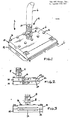
- the apparatus 2 of the present invention has a connector 4 which is connected to a fluid carbon dioxide storage facility (not shown) via a conduit 6.
- the conduit 6 may be a steel reinforced Teflon hose or any other suitable connecting means which enables the fluid carbon dioxide to flow from the source to the connector 4.
- the connector 4 includes a body 8 having a hole or aperture 10 extending therethrough.
- the connector 4 may be permanently or removably secured to the apparatus 2 such as by thread and groove engagement.
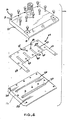
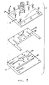
- the apparatus 2 also includes a pair of plates 12 and 14 which are of complementary shape and superimposable one over the other. As shown best in Figures 2 and 3, the plates 12 and 14 may be secured to each other by a plurality of evenly distributed screws 16 which are insertable into respective holes 18 and 20 or by other suitable securing means.
- one embodiment of the invention provides a transverse groove 28 on the bottom surface 13 of the top plate 12 extending along a substantial width of the top plate.
- the top surface 15 of the bottom plate 14 is provided with a complementary transverse groove 30 of like dimension such that when the plates are superimposed they form a symmetrical coalescing chamber (also referred to herein as the 'second chamber') for transforming fine droplets of carbon dioxide into larger droplets of carbon dioxide which subsequently solidify and exit out of an ejection port 32 as explained in detail hereinafter.
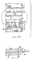
- the bottom plate 14 is also provided with another transverse groove 26 which is rearward of the groove 30 and aligned with a hole or aperture 33 in the top plate 12 (see Figure 5A) (in which the connector 4 is received) to provide a passageway for the flow of the fluid carbon dioxide from the source to the groove 26.
- the top plate does not have a groove complementary to the groove 26.
- FIG. 5B An alternative embodiment is shown in Figure 5B wherein the top plate is provided with a transverse groove 24 which is complementary in shape to the groove 26 in the bottom plate 14. When the respective plates 12 and 14 are superimposed, grooves 24 and 26 from a symmetrial carbon dioxide fluid receiving chamber.
- a symmetrical coalescing chamber is preferred in order to achieve maximum uniform distribution of the solid particles of carbon dioxide as they are formed in the chamber and evacuated through the ejection port 32.
- the fluid receiving chamber need not be symmetrical since the incoming fluid is inherently evenly distributed. It is preferred to form the top plate without the groove 24 in order to minimise manufacturing costs.
- a relatively thin film or foil like member 34 Interposed between the plates 12 and 14 is a relatively thin film or foil like member 34 which provides a fixed means of metering the carbon dioxide mixture from the first chamber to the second chamber.
- the film-like member 34 includes opposed arms 36 and 38 which run along opposed sides of the plates 12 and 14. There is also provided at least two projections or fingers 40. Adjacent fingers 40 are separated from each other by a distance "x" thereby to define at least one channel 42. One end 44 of the channel 42 is in flow communication with the first chamber as shown best in Figures 5A and 5B and the other end 46 is in flow communication with the second chamber thereby to provide a passageway for the flow of carbon dioxide from the first to the second chamber.
- the film-like member 34 is also provided with an orifice 35 which co-operates with the holes or apertures 10 and 33 to provide a continuous passageway for the flow of the fluid carbon dioxide from the source to the first chamber.
- the respective forward portions 48 and 50 of the superimposed plates 12 and 14 define therebetween a channel 52 which receives the fluid carbon dioxide from the second chamber and in which the larger droplets of carbon dioxide expand and form solid particles prior to exiting through the ejection port 32 in which the channel 52 terminates.
- the ejection port 32 includes opposed walls 54, 56 shown best in Figure 6 which diverge or taper outwardly in a manner which enables the solid/gas mixture to flow outwardly therefrom at a sufficient speed and force to remove small particles from the substrate without damaging the substrate.
- the transverse groove 26 may be provided with an enlarged area or reservoir 58 which is aligned with and of the same cross-sectional area as the hole 10 of the receiving assembly 4. This embodiment enables a larger volume of fluid to be supplied to the first chamber than the specific embodiment shown in Figure 4.
- the source of carbon dioxide utilised in this invention is a fluid source which is stored at a temperature and pressure above what is known as the "triple point" which is that point where either a liquid or a gas will turn to a solid upon removal of heat. It will be appreciated that, unless the fluid carbon dioxide is above the triple point, it will not pass the orifice of the apparatus of this invention.
- the source of fluid carbon dioxide is at a minimum pressure of at least the freezing point pressure, about 65 psia and is, preferably, at a pressure of at least about 300 psia. Moreover, the fluid carbon dioxide needs to be under sufficient pressure to make possible a controlled flow through the first chamber and into the second chamber formed by grooves 28 and 30. Typically, the fluid carbon dioxide is stored at ambient temperature at a pressure of from about 300 to 1000 psia, preferably at about 750 psia. It is necessary that the enthalpy of the fluid carbon dioxide feed stream under the above pressures be below about 135 BTU per pound, based on an enthalpy of zero at 150 psia for a saturated liquid.
- the enthalpy requirement is essential regardless of whether the fluid carbon dioxide is in a liquid, gaseous or, more commonly, a mixture, which typically is predominately liquid.
- the enthalpy of the store fluid carbon dioxide can be from about 20 to 135 BTU/lb.
- the enthalpy can be from about 110 to 135 BTU/lb.
- the film like member 34 has at least one channel 42, preferably at least two channels and most preferably the number of channels selected is dependent on the width of the channels. That is, the total width of the channels 42 (i.e. the sum of the distances "x") is desirably at least 10% of the total width of the ejection port 32 as shown in Figure 1 as the distance "y".
- the preferred total channel width is in the range of from about 10 to 20% of the width of the ejection port 32.
- the selection of the number of channels is in part determined by manufacturing considerations in that the greater the number of fingers 40, the greater the likelihood that the thin fingers will not lie perfectly flat in the assembled apparatus. On the other hand, the lower the number of channels, the less control over the distribution of the carbon dioxide as it passes from the first to the second chamber.
- the thickness of the film like member 34 is likewise dependent on manufacturing considerations as well as flow control. For practical purposes, it is difficult to manufacture the film below 0.001". While there is no particularly desirable upper range, about 0.001 to 0.020" has been found to be a suitable thickness for the film 34. It is also desirable to make the film 34 of a flexible material to insure flat face-to-face contact with the plate surfaces when the plates are secured to each other.
- the transverse grooves 26, 28 and 30 and, optionally 24, are preferably equidimensional having a length and cross-sectional area dependent on the like dimensions of the ejection port 32.
- the length of the grooves 28 and 30 is about equal to the width of the ejection port 32.
- the length of the transverse grooves 24 and 26 is at least sufficient to reach the outermost channels 42.
- the cross-sectional area of the chambers should be sufficient to maintain the pressure in the second chamber in the range of from about 80 to 160 psia, preferably about 100 psia.
- the fluid carbon dioxide exits a storage tank or other source of carbon dioxide and proceeds through the connecting means 6 to the receiving assembly 4 and flows via apertures 10, 33 and 35 the receiving chamber formed by groove 26 alone (see Figure 5A) or by grooves 24 and 26 (see Figure 5B).
- the fluid carbon dioxide flows out of the first chamber to the second chamber the channels 42.
- the fluid carbon dioxide flows out of the first chamber it expands along a constant enthalpy line to about 80-100 psia as it enters the coalescing chamber formed by grooves 28 and 30. As a result, a portion of the fluid carbon dioxide is converted to fine droplets.
- the state of the fluid carbon dioxide feed will determine the degree of change that takes place in the coalescing chamber, e.g. saturated gas or pure liquid carbon dioxide in the source container will undergo a proportionately greater change than liquid/gas mixtures.
- the equilibrium temperature in the second chamber is typically about -57 o F and, if the source is room temperature liquid carbon dioxide, the carbon dioxide in second chamber is formed into a mixture of about 50% fine liquid droplets and 50% carbon dioxide vapour.
- the fine liquid droplet/gas mixture continues to flow through the second chamber. As a result of additional exposure to the pressure drop, the fine liquid droplets coalesce into larger liquid droplets.
- the larger liquid droplets/gas mixture forms into a solid/gas mixture as the feed proceeds through the channel 52 and out the ejection port 32.
- Walls 54, 56 forming the ejection port 32 are suitably tapered at an angle of divergence of about 4 o to 8 o , preferably about 6 o . If the angle of divergence is too great (i.e. above about 15 o ), the intensity of the stream of solid/gas carbon dioxide will be reduced below that which is necessary to clean most substrates.
- the second chamber serves to coalesce the fine liquid droplets into larger liquid droplets.
- the larger liquid droplets form minute, solid carbon dioxide particles as the carbon dioxide expands and exits toward the substrate at the ejection port 32.
- the solid/gaseous carbon dioxide having the requisite enthalpy as described above is subjected to desired pressure drops from the first chamber through the channels 42 into the second chamber, the orifice 52 and ejection port 32.
- Pure carbon dioxide may be acceptable for many applications using the present invention, for example, in the field of optics, including the cleaning of telescope mirrors.
- ultrapure carbon dioxide 99.99% or higher
- purity is to be interpreted with respect to undesirable compounds for a particular application.
- mercaptans may be on the list of impurities for a given application whereas nitrogen may be present.
- Applications that require ultrapure carbon dioxide include the cleaning of silicon wafers for semiconductor fabrication, disc drives, hybrid circuit assemblies and compact discs.
- the invention can effectively remove particles, hydrocarbon films particles embedded in oil and fingerprints.
- Applications include, but are not limited to the cleaning of optical apparatus, space craft, semiconductor wafers, and equipment for contaminant-free manufacturing processes.
- a cylinder of Airco "Spectra Clean” carbon dioxide (the high purity CO2) equipped for liquid withdrawal was connected via a four foot length of 1/8 inch O.D. stainless steel tubing to the inlet fitting of a nozzle of the type shown in Figures 4 and 5A.
- the nozzle was made of Type 316 stainless steel having an overall width of 2 1/2 inches and an outlet aperture of 2 inches.
- the distance between the first chamber and the second chamber i.e. the length of the metering channels 42
- the length of the second channel extending from the coalescing chamber to the beginning of the divergent walls 54, 56 of the ejection port 32 was 9/16 inch.
- the walls 54, 56 were tapered at angle 6 o thereby providing an expansion ratio of 4:1.
- the film-like elements employed in the respective nozzles each had a thickness of 0.001 inch and included four metering channels 42.
- the channels 42 of the respective film-like members 34 were 0.40, 0.60 and 0.80 inches, respectively.
- the substrate to be cleaned was a silicon wafer which was artificially contaminated with zinc sulfide powder dispersed in ethyl alcohol.
- the nozzle was operated in free air for about 5 seconds to cool down and establish stable flow of the product mixture. Then the nozzle was moved to a position of 45 o with respect the substrate surface at a distance of about 3/4 inch.
- Liquid carbon dioxide from the cylinder was supplied to the nozzle at a pressure of 850 psia.
- the 0.040 inch wide nozzle produced a flow rate of only 2 scfm and a coalescing chamber pressure of less than 80 psia.
- the solid carbon dioxide particles produced were too big and moved at too slow a velocity to remove the zinc sulfide particles from the substrate.
- Both the 0.060 and 0.080 inch wide nozzles were effective in removing the contaminated particles as they produced a smooth stable flow of solid carbon dioxide particles at a flow rate of 3.4 scfm (standard cubic feet per minute) and 4.7 scfm, respectively.
- the substrate was examined under ultraviolet light which causes the contaminants to fluoresce. No trace of the contaminants was present on the substrates.
Landscapes
- Chemical & Material Sciences (AREA)
- Organic Chemistry (AREA)
- Chemical Kinetics & Catalysis (AREA)
- Inorganic Chemistry (AREA)
- Engineering & Computer Science (AREA)
- Mechanical Engineering (AREA)
- Physical Or Chemical Processes And Apparatus (AREA)
- Cleaning Or Drying Semiconductors (AREA)
- Nozzles (AREA)
Applications Claiming Priority (2)
| Application Number | Priority Date | Filing Date | Title |
|---|---|---|---|
| US07/280,775 US4962891A (en) | 1988-12-06 | 1988-12-06 | Apparatus for removing small particles from a substrate |
| US280775 | 1999-03-29 |
Publications (1)
| Publication Number | Publication Date |
|---|---|
| EP0372902A1 true EP0372902A1 (de) | 1990-06-13 |
Family
ID=23074588
Family Applications (1)
| Application Number | Title | Priority Date | Filing Date |
|---|---|---|---|
| EP89312660A Ceased EP0372902A1 (de) | 1988-12-06 | 1989-12-05 | Apparat zum Entfernen von kleinen Teilchen von einem Substrat |
Country Status (5)
| Country | Link |
|---|---|
| US (1) | US4962891A (de) |
| EP (1) | EP0372902A1 (de) |
| JP (1) | JPH079899B2 (de) |
| AU (1) | AU616083B2 (de) |
| ZA (1) | ZA899287B (de) |
Cited By (7)
| Publication number | Priority date | Publication date | Assignee | Title |
|---|---|---|---|---|
| AU658790B1 (en) * | 1993-12-23 | 1995-04-27 | Boc, Inc. | CO2 jet spray system employing a thermal CO2 snow plume sensor |
| US5609305A (en) * | 1994-09-19 | 1997-03-11 | Vortec Corporation | Apparatus for providing an air curtain |
| US5622315A (en) * | 1995-03-14 | 1997-04-22 | Nordson Corporation | Adjustable slot goating die |
| NL1013978C2 (nl) * | 1999-12-29 | 2001-07-02 | Huibert Konings | Inrichting voor het bewerken van oppervlakken met koolzuurkristallen in een koolzuurgasstraal. |
| US6852011B2 (en) | 2001-12-07 | 2005-02-08 | The Boc Group, Plc | Weld preparation method |
| EP1795266A1 (de) * | 2005-12-09 | 2007-06-13 | DS Smith Kaysersberg | Verfahren und Blasdüse zum Entfernen der Späne von Alveolarplatten |
| US7461797B2 (en) | 2004-11-10 | 2008-12-09 | Spraying Systems, Co. | Air knife |
Families Citing this family (45)
| Publication number | Priority date | Publication date | Assignee | Title |
|---|---|---|---|---|
| US5165601A (en) * | 1990-04-11 | 1992-11-24 | Terronics Development Corporation | Nozzle for low resistivity flowable material |
| JPH0435872A (ja) * | 1990-05-30 | 1992-02-06 | Mitsubishi Electric Corp | 凍結粒子を使用した研磨装置 |
| US5315793A (en) * | 1991-10-01 | 1994-05-31 | Hughes Aircraft Company | System for precision cleaning by jet spray |
| US5209028A (en) * | 1992-04-15 | 1993-05-11 | Air Products And Chemicals, Inc. | Apparatus to clean solid surfaces using a cryogenic aerosol |
| EP0647170B1 (de) * | 1992-06-22 | 2000-05-17 | Minnesota Mining And Manufacturing Company | Verfahren und vorrichtung zum entfernen von abfallstoffen von optischen floppy-disk-medien |
| US5409418A (en) * | 1992-09-28 | 1995-04-25 | Hughes Aircraft Company | Electrostatic discharge control during jet spray |
| US5265383A (en) * | 1992-11-20 | 1993-11-30 | Church & Dwight Co., Inc. | Fan nozzle |
| US6177126B1 (en) * | 1993-03-31 | 2001-01-23 | Nycomed Arzneimittel Gmbh | Process for the production of a material for sealing and healing wounds |
| US5545073A (en) * | 1993-04-05 | 1996-08-13 | Ford Motor Company | Silicon micromachined CO2 cleaning nozzle and method |
| US5354384A (en) * | 1993-04-30 | 1994-10-11 | Hughes Aircraft Company | Method for cleaning surface by heating and a stream of snow |
| US5377911A (en) * | 1993-06-14 | 1995-01-03 | International Business Machines Corporation | Apparatus for producing cryogenic aerosol |
| US5366156A (en) * | 1993-06-14 | 1994-11-22 | International Business Machines Corporation | Nozzle apparatus for producing aerosol |
| US5390450A (en) * | 1993-11-08 | 1995-02-21 | Ford Motor Company | Supersonic exhaust nozzle having reduced noise levels for CO2 cleaning system |
| US5405283A (en) * | 1993-11-08 | 1995-04-11 | Ford Motor Company | CO2 cleaning system and method |
| US5514024A (en) * | 1993-11-08 | 1996-05-07 | Ford Motor Company | Nozzle for enhanced mixing in CO2 cleaning system |
| US5931721A (en) * | 1994-11-07 | 1999-08-03 | Sumitomo Heavy Industries, Ltd. | Aerosol surface processing |
| US5967156A (en) * | 1994-11-07 | 1999-10-19 | Krytek Corporation | Processing a surface |
| US6173916B1 (en) | 1994-12-15 | 2001-01-16 | Eco-Snow Systems, Inc. | CO2jet spray nozzles with multiple orifices |
| US5679062A (en) * | 1995-05-05 | 1997-10-21 | Ford Motor Company | CO2 cleaning nozzle and method with enhanced mixing zones |
| US5616067A (en) * | 1996-01-16 | 1997-04-01 | Ford Motor Company | CO2 nozzle and method for cleaning pressure-sensitive surfaces |
| US5810942A (en) * | 1996-09-11 | 1998-09-22 | Fsi International, Inc. | Aerodynamic aerosol chamber |
| US6036786A (en) * | 1997-06-11 | 2000-03-14 | Fsi International Inc. | Eliminating stiction with the use of cryogenic aerosol |
| US5961732A (en) * | 1997-06-11 | 1999-10-05 | Fsi International, Inc | Treating substrates by producing and controlling a cryogenic aerosol |
| DK173470B1 (da) * | 1998-06-18 | 2000-12-04 | Casco As | Spreder til udlægning af et fluidum, såsom lim |
| US5944581A (en) * | 1998-07-13 | 1999-08-31 | Ford Motor Company | CO2 cleaning system and method |
| SE512588C2 (sv) * | 1998-08-06 | 2000-04-03 | Aga Ab | Metod och anordning för punktkylning av yta |
| US6500758B1 (en) | 2000-09-12 | 2002-12-31 | Eco-Snow Systems, Inc. | Method for selective metal film layer removal using carbon dioxide jet spray |
| JP2004009257A (ja) * | 2002-06-10 | 2004-01-15 | Macoho Co Ltd | ピーニング処理方法 |
| US7297286B2 (en) * | 2002-07-29 | 2007-11-20 | Nanoclean Technologies, Inc. | Methods for resist stripping and other processes for cleaning surfaces substantially free of contaminants |
| US7101260B2 (en) * | 2002-07-29 | 2006-09-05 | Nanoclean Technologies, Inc. | Methods for resist stripping and other processes for cleaning surfaces substantially free of contaminants |
| US6764385B2 (en) * | 2002-07-29 | 2004-07-20 | Nanoclean Technologies, Inc. | Methods for resist stripping and cleaning surfaces substantially free of contaminants |
| US7066789B2 (en) * | 2002-07-29 | 2006-06-27 | Manoclean Technologies, Inc. | Methods for resist stripping and other processes for cleaning surfaces substantially free of contaminants |
| US7134941B2 (en) * | 2002-07-29 | 2006-11-14 | Nanoclean Technologies, Inc. | Methods for residue removal and corrosion prevention in a post-metal etch process |
| DE102005005638B3 (de) * | 2005-02-05 | 2006-02-09 | Cryosnow Gmbh | Verfahren und Vorrichtung zum Reinigen, Aktivieren oder Vorbehandeln von Werkstücken mittels Kohlendioxidschnee-Strahlen |
| WO2008031185A1 (en) * | 2006-09-13 | 2008-03-20 | Doben Limited | Nozzle assembly for cold gas dynamic spray system |
| RU2359088C1 (ru) * | 2007-12-17 | 2009-06-20 | Общество с ограниченной ответственностью "Промышленные вакуумные системы" | Сопло для обмыва внутренней поверхности чаши унитаза |
| JP5180679B2 (ja) * | 2008-05-19 | 2013-04-10 | 昭和電工ガスプロダクツ株式会社 | ドライアイス粒子の噴射装置 |
| US8454409B2 (en) | 2009-09-10 | 2013-06-04 | Rave N.P., Inc. | CO2 nozzles |
| DE102011011850A1 (de) * | 2011-02-21 | 2012-08-23 | Dürr Systems GmbH | Düsenkopf zur Applikation eines Dämmstoffmittels |
| JP4880796B1 (ja) * | 2011-06-27 | 2012-02-22 | 孝雄 川谷 | 介助用車椅子 |
| KR102367953B1 (ko) * | 2015-01-15 | 2022-02-25 | 삼성디스플레이 주식회사 | 분사 유닛 및 이를 이용한 기판 세정 장치 |
| US9597703B2 (en) * | 2015-02-18 | 2017-03-21 | Lam Research Ag | Slit nozzle |
| DE102015009676A1 (de) | 2015-07-25 | 2017-01-26 | Messer Group Gmbh | Verfahren zum Behandeln von Oberflächen mit einem Strahlmittel aus Trockeneispartikeln |
| DE102016014269A1 (de) * | 2016-11-30 | 2018-05-30 | Dürr Systems Ag | Düsenvorrichtung mit zumindest zwei Düsenplatten und zumindest drei Öffnungen |
| DE102016014270A1 (de) | 2016-11-30 | 2018-05-30 | Dürr Systems Ag | Düsenvorrichtung zur Ausgabe von zwei sich annähernden Strahlen eines Abgabemediums |
Citations (4)
| Publication number | Priority date | Publication date | Assignee | Title |
|---|---|---|---|---|
| US2743554A (en) * | 1952-04-19 | 1956-05-01 | Int Resistance Co | Apparatus for blast etching electrical devices |
| US3716194A (en) * | 1970-09-16 | 1973-02-13 | Economics Lab | Combination high pressure venturi and spray forming nozzle |
| US4347805A (en) * | 1976-05-12 | 1982-09-07 | National Steel Corporation | Apparatus for liquid coating thickness control |
| EP0288263A2 (de) * | 1987-04-22 | 1988-10-26 | The BOC Group, Inc. | Apparat und Verfahren zum Entfernen von sehr kleinen Teilchen aus einem Substrat |
Family Cites Families (4)
| Publication number | Priority date | Publication date | Assignee | Title |
|---|---|---|---|---|
| US2985387A (en) * | 1959-10-13 | 1961-05-23 | Spencer Chem Co | Liquid material distributor |
| CH503562A (de) * | 1969-02-25 | 1971-02-28 | Eduard Dr Lusser | Vorrichtung zum Brennen von Löchern in Beton, Mauerwerk, Gestein oder Metall |
| US3726659A (en) * | 1970-10-02 | 1973-04-10 | Owens Illinois Inc | Method and apparatus for forming a finish on a glass container |
| JPS603555B2 (ja) * | 1979-02-13 | 1985-01-29 | 株式会社島津製作所 | 物質表面除去方法 |
-
1988
- 1988-12-06 US US07/280,775 patent/US4962891A/en not_active Expired - Lifetime
-
1989
- 1989-12-05 EP EP89312660A patent/EP0372902A1/de not_active Ceased
- 1989-12-05 ZA ZA899287A patent/ZA899287B/xx unknown
- 1989-12-05 AU AU45921/89A patent/AU616083B2/en not_active Ceased
- 1989-12-06 JP JP1317435A patent/JPH079899B2/ja not_active Expired - Fee Related
Patent Citations (4)
| Publication number | Priority date | Publication date | Assignee | Title |
|---|---|---|---|---|
| US2743554A (en) * | 1952-04-19 | 1956-05-01 | Int Resistance Co | Apparatus for blast etching electrical devices |
| US3716194A (en) * | 1970-09-16 | 1973-02-13 | Economics Lab | Combination high pressure venturi and spray forming nozzle |
| US4347805A (en) * | 1976-05-12 | 1982-09-07 | National Steel Corporation | Apparatus for liquid coating thickness control |
| EP0288263A2 (de) * | 1987-04-22 | 1988-10-26 | The BOC Group, Inc. | Apparat und Verfahren zum Entfernen von sehr kleinen Teilchen aus einem Substrat |
Cited By (8)
| Publication number | Priority date | Publication date | Assignee | Title |
|---|---|---|---|---|
| AU658790B1 (en) * | 1993-12-23 | 1995-04-27 | Boc, Inc. | CO2 jet spray system employing a thermal CO2 snow plume sensor |
| US5609305A (en) * | 1994-09-19 | 1997-03-11 | Vortec Corporation | Apparatus for providing an air curtain |
| US5622315A (en) * | 1995-03-14 | 1997-04-22 | Nordson Corporation | Adjustable slot goating die |
| NL1013978C2 (nl) * | 1999-12-29 | 2001-07-02 | Huibert Konings | Inrichting voor het bewerken van oppervlakken met koolzuurkristallen in een koolzuurgasstraal. |
| US6852011B2 (en) | 2001-12-07 | 2005-02-08 | The Boc Group, Plc | Weld preparation method |
| US7461797B2 (en) | 2004-11-10 | 2008-12-09 | Spraying Systems, Co. | Air knife |
| EP1795266A1 (de) * | 2005-12-09 | 2007-06-13 | DS Smith Kaysersberg | Verfahren und Blasdüse zum Entfernen der Späne von Alveolarplatten |
| FR2894503A1 (fr) * | 2005-12-09 | 2007-06-15 | Ds Smith Kaysersberg Soc Par A | Procede de depoussierage de plaques alveolaires, soufflette de depoussierage |
Also Published As
| Publication number | Publication date |
|---|---|
| ZA899287B (en) | 1991-03-27 |
| AU4592189A (en) | 1990-06-14 |
| AU616083B2 (en) | 1991-10-17 |
| JPH03114227A (ja) | 1991-05-15 |
| JPH079899B2 (ja) | 1995-02-01 |
| US4962891A (en) | 1990-10-16 |
Similar Documents
| Publication | Publication Date | Title |
|---|---|---|
| US4962891A (en) | Apparatus for removing small particles from a substrate | |
| EP0288263B1 (de) | Apparat und Verfahren zum Entfernen von sehr kleinen Teilchen aus einem Substrat | |
| AU729427B2 (en) | Gas-assisted atomizing device | |
| US9192054B2 (en) | Apparatus for anisotropic focusing | |
| EP0891945B1 (de) | Vorrichtung zur Herstellung von feinen Schneeteilchen mittels eines flüssigen Kohlendioxidstroms | |
| US6846413B1 (en) | Microstructured filter | |
| US5115972A (en) | Spray die for producing spray fans | |
| US6378788B1 (en) | Rayleigh-breakup atomizing devices and methods of making rayleigh-breakup atomizing devices | |
| JP2006310885A (ja) | 低温エーロゾルの製造および制御による基材の処理 | |
| US4991541A (en) | Device and process for treating fine particles | |
| JPH06220641A (ja) | 化学的蒸着膜工程のための反応液体の気化 | |
| SE466520B (sv) | Anordning och foerfarande foer kontinuerlig provtagning och analys av en vaetska | |
| KR100419299B1 (ko) | 표면 세정을 위한 승화성 고체 입자 분사용 노즐 | |
| EP0405527B1 (de) | Zerstäuber zur Bildung einer dünnen Schicht | |
| JP2001522309A (ja) | 融解ロウ分配システム | |
| JPS6012095B2 (ja) | 流動性の液体をプロペラントガス中で超微細な粒子とする方法および噴霧装置 | |
| GB2175414A (en) | Controlling density of particles | |
| WO2024163995A1 (en) | High-definition aerosol printing using an optimized aerosol distribution and hydrodynamic lens system | |
| WO1983002736A1 (en) | Variable gas atomization | |
| JPH0729818A (ja) | 基板処理装置 | |
| JPS62250945A (ja) | 気相処理装置 | |
| JPH0699105A (ja) | 霧化ノズル | |
| JPS6242414A (ja) | 気相励起装置 | |
| JPS61220764A (ja) | 微粒子流の速度制御方法 | |
| JPS61220730A (ja) | 微粒子流の流れ制御装置 |
Legal Events
| Date | Code | Title | Description |
|---|---|---|---|
| PUAI | Public reference made under article 153(3) epc to a published international application that has entered the european phase |
Free format text: ORIGINAL CODE: 0009012 |
|
| AK | Designated contracting states |
Kind code of ref document: A1 Designated state(s): BE DE FR GB IT NL |
|
| 17P | Request for examination filed |
Effective date: 19901213 |
|
| 17Q | First examination report despatched |
Effective date: 19920313 |
|
| STAA | Information on the status of an ep patent application or granted ep patent |
Free format text: STATUS: THE APPLICATION HAS BEEN REFUSED |
|
| 18R | Application refused |
Effective date: 19931204 |