EP0373490A2 - Boîte de vitesse à rapport de transmission continuement variable - Google Patents
Boîte de vitesse à rapport de transmission continuement variable Download PDFInfo
- Publication number
- EP0373490A2 EP0373490A2 EP89122450A EP89122450A EP0373490A2 EP 0373490 A2 EP0373490 A2 EP 0373490A2 EP 89122450 A EP89122450 A EP 89122450A EP 89122450 A EP89122450 A EP 89122450A EP 0373490 A2 EP0373490 A2 EP 0373490A2
- Authority
- EP
- European Patent Office
- Prior art keywords
- transmission
- case
- pulleys
- driving
- brake
- Prior art date
- Legal status (The legal status is an assumption and is not a legal conclusion. Google has not performed a legal analysis and makes no representation as to the accuracy of the status listed.)
- Granted
Links
Images







Classifications
-
- F—MECHANICAL ENGINEERING; LIGHTING; HEATING; WEAPONS; BLASTING
- F16—ENGINEERING ELEMENTS AND UNITS; GENERAL MEASURES FOR PRODUCING AND MAINTAINING EFFECTIVE FUNCTIONING OF MACHINES OR INSTALLATIONS; THERMAL INSULATION IN GENERAL
- F16H—GEARING
- F16H47/00—Combinations of mechanical gearing with fluid clutches or fluid gearing
- F16H47/06—Combinations of mechanical gearing with fluid clutches or fluid gearing the fluid gearing being of the hydrokinetic type
- F16H47/065—Combinations of mechanical gearing with fluid clutches or fluid gearing the fluid gearing being of the hydrokinetic type the mechanical gearing comprising gearing of the friction or endless flexible member type
-
- F—MECHANICAL ENGINEERING; LIGHTING; HEATING; WEAPONS; BLASTING
- F16—ENGINEERING ELEMENTS AND UNITS; GENERAL MEASURES FOR PRODUCING AND MAINTAINING EFFECTIVE FUNCTIONING OF MACHINES OR INSTALLATIONS; THERMAL INSULATION IN GENERAL
- F16H—GEARING
- F16H37/00—Combinations of mechanical gearings, not provided for in groups F16H1/00 - F16H35/00
- F16H37/02—Combinations of mechanical gearings, not provided for in groups F16H1/00 - F16H35/00 comprising essentially only toothed or friction gearings
- F16H37/021—Combinations of mechanical gearings, not provided for in groups F16H1/00 - F16H35/00 comprising essentially only toothed or friction gearings toothed gearing combined with continuously variable friction gearing
Definitions
- the present invention relates to a non-stage automatic transmission for vehicles and, particularly, to a non-stage automatic transmission for varying the groove widths between adjustable pulleys to change the reduction ratio and thereby control the speed of the vehicle.
- transmissions connect between internal combustion engines and driving wheels.
- the transmission controls the driving force of driving wheels and the driving speed, depending on a driving condition varying extensively, and thus sufficiently optimizes the performance of an internal combustion engine.
- a belt driving type of non-stage automatic transmission serves to change, by hydraulic pressure, the groove widths formed between respective driving and driven adjustable pulleys.
- the reduction ration (belt ratio) relative to a driving force transmitted by the belt may be changed.
- a further problem in the existing non-stage transmissions is that the torque convertor, the oil pump, the driving pulley, the clutch, and the brake are positioned in a row from the engine side along a driving side shaft of the transmission. It is difficult and practically disadvantageous to arrange such a transmission in the limited engine space, because the overall length is large.
- the belt-pulley arrangement requires a multi-shaft structure which, because of the layout of bearings which support multiple shafts, structure is complicated and inevitably leads to high costs and economic disadvantages.
- an object of the present invention is to provide a non-stage automatic transmission which can be composed in smaller size and easily arranged in the engine space or room.
- This object is addressed by positioning in turn a fluid coupling having normal and reverse rotating functions, an oil pump producing a driving hydraulic pressure, a reverse driving brake, a forward-reverse shift clutch, and an adjustable driving pulley in a row from engine side along the driving rotation shaft of the transmission.
- non-stage transmission is disclosed in Japanese Patent No. 59-99165.
- an input shaft of a belt type of non-stage automatic transmission is an output shaft, and on the output shaft, a non-stage automatic transmission, a planetary gear for shifting advance and reverse, an oil pump, and a three-element one-stage type of torque convertor are in turn positioned from the engine side.
- a torque convertor (a fluid coupling of PTS type in which a pump impeller, turbine runner, and a stator are in turn positioned, or of PST type in which a pump impeller, a stator and a turbine runner are in turn positioned) is used, and the stator of the torque convertor is either locked or freely rotatable, whereby it serves to operate as a reverse rotation torque convertor or a normal rotation fluid coupling, respectively.
- a fluid coupling for example, a torque convertor is in a condition which they are apt to slip with respect to each other, and a problem of reduced efficiency of driving power arises.
- another object of the invention is, in order to improve the above-mentioned problem, to provide a non-stage transmission with a fluid coupling having a pump impeller, a stator to be locked by a brake, and a turbine runner in turn positioned and installed therein, and having a built-in direct clutch so as to prevent cavitation.
- a fluid coupling having a pump impeller, a stator to be locked by a brake, and a turbine runner in turn positioned and installed therein, and having a built-in direct clutch so as to prevent cavitation.
- the fluid coupling has a pump impeller rotatably connected with the internal combustion engine, a rotating stator which can be locked by a braking mechanism, and a turbine fixed on an output side shaft which is in turn positioned on the pulley side. By releasing or locking the stator, the turbine rotates normally or reversely to shift the direction of rotation of the belt, and thus advance or reverse the vehicle.
- a further object of the invention is to design a minimally-sized non-stage transmission equipped with a fluid coupling and which can be easily arranged in an engine room.
- This object is addressed by installing a braking operator of a working mechanism which operates a braking mechanism in a hollow portion formed inside of a retaining portion of a brake side casing, which casing also holds a bearing supporting an output side shaft of the fluid coupling.
- Such a construction makes it unnecessary to arrange a braking operator together with other components in a row in a non-stage transmission, so the non-stage transmission equipped with a fluid coupling can be made smaller in overall length and can be designed to a minimum size and length.
- the smaller non-stage transmission has the advantage of arrangement.
- a transmission case 202 comprises a main case 204, a front case 206 fitted between the main case 204 and internal combustion engine (not shown), a rear case 208 fitted on the side of the main case 204 opposite the internal combustion engine, a subcase 210 fixed in said main case 204, and a rear cover case 212 fitted on the side of the main case 204 opposite the internal combustion engine.
- a belt type transmission mechanism 214 is installed and enclosed by the rear case 208 and the rear cover 212.
- a driving side shaft 216 and a driven side shaft 218 -- or rotation shafts -- are each supported at one axial end by said front case 206, and at the other axial end by the main case 204, respectively.
- a transfer gear 222 and a differential gear 224 composing a driving-power transmitting mechanism 220 are installed and enclosed by said front case 206 and said subcase 210 fixed in said main case 204.
- a transfer gear shaft 226 -- or a rotation shaft of the transfer gear 222 -- is supported at one axial end by said front case 204, and at the other axial end by said subcase 210.
- a differential gear case 228 -- a rotation shaft of the differential gear 224 -- has one axial end supported by the front case 206, and another axial end supported by said main case 204.
- another known transmission case 302 of a non-stage automatic transmission 300 comprises a main case 304, a front case 306 fitted on the side of the main case 304 close to an internal combustion engine (not shown), a rear case 308 fitted on the side of the main case 304 opposite the internal combustion engine, a subcase 310 fixed on said main case 304, a front cover case 312 fitted on the side of the front case 306 close to the internal combustion engine, and a rear cover case 314 on the side of the rear case 308 opposite the internal combustion engine.
- a belt type transmission mechanism is installed and enclosed by said main case 304, said front case 306, said rear case 308, and said subcase 310.
- a driving side shaft 318 and a driven side shaft 320 have respective axial ends supported by said main case 304 and said front case 306, and respective opposite axial ends supported by said rear case 308 and said subcase 310.
- a transfer gear 324 and a differential gear 326 composing a driving-power transmitting mechanism are installed and enclosed by said front case 306, said front cover case 312, and said main case 304.
- Transfer gear shaft 328 -- a rotation shaft of a transfer gear 324 -- has one axial end supported by said front case 306, and another axial end supported by said main case 304.
- a differential gear case 330 -- a rotation shaft of the differential gear 326 -- has one axial end supported by said front case 306, and another axial end supported by said main case 304.
- the transmission case 202 comprises the main case 204, the front case 206, the rear case 208, the subcase 210, and the rear cover 212.
- the number of case members forming the transmission case 202 amounts to six.
- the transmission case 302 comprises the main case 304, the front case 306, the rear case 308, the subcase 310, the front cover 312, and the rear cover 314.
- Including an oil pan (not shown) fitted on the transmission case 302 the number of case members amounts to seven. Accordingly, the traditional non-stage automatic transmission has the disadvantage of a large number of case members which is accompanied by rising costs, and carrying out maintenance is not easy because of difficult access to the mechanisms in the transmission case.
- another object of the invention is to provide a non-stage automatic transmission for a vehicle in which the number of components composing the transmission case can be reduced, and in which each mechanism in the transmission case is simply accessible to easily carry out maintenance.
- This object is addressed by providing a transmission case which comprises a main case, and front and rear cases respectively fitted on the main case, such that one axial end of each rotation shaft of said mechanism is supported, enclosed, and installed by the main case, and another axial end of each rotation shaft of each mechanism is supported, enclosed, and installed by either said front case or said rear case.
- the construction has at least two less case elements than the known cases, and each mechanism will be easily accessible by removing either the front case or the rear case.
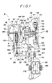
- the driving side pulley 4 has a pulley member or half 14 axially and nonrotatably fixed on a driving side shaft 12 and a pulley member or half 16 nonrotatably attached on the driving side shaft 12 but movable axially with respect thereto.
- Oil is conducted into an oil chamber 20 between the pulley member 16 and a housing 18 positioned on the back side of the pulley member 16.
- the pulley member 16 is axially moved with respect to the shaft 12 by applying hydraulic pressure thereto, and thus the width of a driving groove 22 formed between the pulley members 14 and 16 is varied.
- the driven side pulley 6 has a pulley member or half 26 axially and nonrotatably fixed on a driven side shaft 24 and a pulley member or half 28 nonrotatably attached on the driven side shaft 24 but movable axially with respect thereto.
- Oil is conducted into an oil chamber 32 formed between the pulley member 28 and a housing 30 positioned on the back side of the pulley member 28.
- the pulley member 28 is axially moved with respect to the driven side shaft 24 by applying hydraulic pressure thereto, whereby the width of the groove 34 formed between the pulley members 26 and 28 is varied.
- a pressing spring 36 urging the member 28 toward the pulley member 26, is compressively positioned.
- the belt 8 is wound around the driving side groove 22 of the driving side pulley 4 and the driven side groove 34, and is tensioned between the pulleys 4 and 6.
- a fluid coupling i.e. a torque convertor 50 is positioned and has a pump impeller 40 connectedly positioned at the side of the internal combustion engine, a stator 44 locked by a braking mechanism 42, and a turbine runner 48 fixed on an output side shaft 46 connected with the driving side shaft 12 on the pulley side.
- the turbine runner 48 can rotate normally and reversely by releasing and locking the stator wheel 44, thus enabling the output side shaft 46 to rotate normally and reversely and to change the direction of rotation of the belt 8.
- a drive plate 54 for driving the fluid coupling 50 is fixed on an internal combustion engine output shaft 52.
- the fluid coupling 50 has the pump impeller 40, stator wheel 44, and turbine runner 48 disposed in a coupling side housing 56.
- the pump impeller 40 is connected with the drive plate 54 through the coupling side housing 56.
- t!:e stator wheel 44 is connected with the braking mechanism 42, as fitted inside of a brake side casing 60 positioned between the pulley side housing 10 and the coupling side housing 56, through a first connecting member 58.
- the stator wheel 44 can be locked and released from the brake side casing 60 according to the operating condition of the braking mechanism 42.
- a direct clutch 62 is positioned to engage the coupling side housing 56 and the turbine runner 48 with each other or to separate them from each other. That is, the direct clutch 62 can connect the internal combustion engine output shaft 52 and the output side shaft 46.
- the direct clutch 62 is built in the torque convertor to prevent a cavitation by engaging and releasing in interlocking with the brake 42.
- the direct clutch 62 is in turn positioned along the direction of hydraulic pressure fluid circulation in the torque convertor 50.
- the direct clutch 62 when the direct clutch 62 operates, that is, when it is disconnected upon reverse operation, the normal reversing state cannot be assured, so that upon reverse operation, the direct clutch 62 is not moved with a pressure in the direction such as to remove the direct clutch away from the drive plate 54 while interlocking with the brake 42, that is, toward the side of the turbine impeller 48.
- fitting the direct clutch 62 into the torque convertor 50 enables the total length of the non-stage transmission to be made smaller, that is, the non-stage transmission can be minimized in size and can be easily arranged in the limited engine room.
- a second connecting member 66 is fixed on the output side shaft 46 and connected with a neutral clutch 68.
- the neutral clutch 68 operates depending upon the hydraulic pressure and connects and disconnects the output side shaft 46 and the driving side shaft 12. Thereby, the turbine runner 48 can be intermittently connected with the driving side pulley member 14 by the neutral clutch 68. That is, the locking and releasing of the neutral clutch 68 causes power transmitted from the turbine runner 48 to the output side shaft 46 to be intermittently transmitted, through the driving pulley 4 and the driven pulley 6, to the following power transmission device, and thus a neutral condition is also possible.
- the coupling side housing 56 forms with the turbine runner 48 a body which is connected to the oil pump 70. Therefore the oil pump 70 will be directly operated by the internal combustion engine side shaft 52.
- the oil pump 70 connects with the hydraulic chambers 20 and 32 through oil passages (not shown).
- the fluid coupling 50 may be, for example, a three-element one-stage type of torque convertor.
- the oil pump 70, the reverse driving brake 42, a forward-reverse shift clutch 68, and the driving pulley 4 are in turn positioned in line from the engine side. Meanwhile, along the flow of hydraulic pressure circulation, the pump impeller 40, a stator wheel 44, turbine runner 48, and wet direct clutch 62 utilizing friction are in turn positioned, and the direct clutch 62 is built in the torque convertor.
- the oil pump 70 operates according to the rotation of the engine side shaft 52, and the oil is sucked from the bottom of the transmission.
- the pump or line pressure is applied to the torque convertor and other components respectively, passing through a line pressure control valve (not shown).
- the three-element one-stage type of torque convertor having normal and reverse functions, said oil pump 70 producing a driving hydraulic pressure, the reverse driving brake 42, the forward-reverse shift clutch 68, and the driving side pulley 4 are positioned in line from the engine side, and the overall length of the non-stage automatic transmission can be smaller in size.
- a driving or neutral phase can be selected by locking up or releasing the forward-reverse shift clutch 68, and the usability of the non-stage automatic transmission becomes higher.
- a retaining portion 60a supporting the bearing 64 is formed in the brake side casing 60.
- a brake piston 76, a braking operator composing an operating mechanism 74 actuating the braking mechanism 42 is placed.
- the brake piston 76 is movable in the axial direction of the output side shaft 46 along the first sliding surface 60e of the retaining portion 60a and the second sliding surface 60f of the covering portion 60b which are parallel to the brake piston 76 by applying a hydraulic pressure through an oil passage 78 formed in the side portion 60c, and contacting with the end 80a of an operating ring 80 positioned outside of the neutral clutch 68.
- the brake piston 76 controls the operation of the braking mechanism 42 with the operating ring 80. That is, said operating mechanism 74 comprises the brake piston 76 and the operating ring 80.
- a stopper 81 causes the brake piston 76 to stop moving.
- the non-stage transmission 2 varies the contact radius of the belt 8 as engaged around the driving pulley 4 and the driven pulley 6, and thus changes the speed reduction ratio steplessly and controls speed.
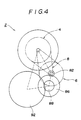
- a reduction drive gear 82 is fixed on the reduction driven shaft 24, and a reduction driven gear 86 fixed on a supporting shaft 84 engages with the reduction drive gear 82.
- a final drive gear 88 is fixed on the supporting shaft 84, and a final gear 92 of a differential unit 90 engages with the final drive gear 88.
- the differential unit 90 is connected to wheels (not shown).
- the internal combustion engine side shaft 52 rotates by the action of an internal combustion engine, and the rotation causes the drive plate 54 to rotate and the fluid coupling 50 to drive.
- the oil pump 70 operates with the rotation of the internal combustion engine side shaft 52, sucks the oil from an oil pan (not shown), and supplies oil to the fluid coupling 50 and other portions.
- the non-stage transmission 2 changes the contact radius of the belt 8 and steplessly controls the speed reduction.
- the space for placing the brake piston 76 is minimized by arranging the brake piston 76 in the hollow 72 of the brake side casing 60, and a saving of space is achieved. Accordingly, the overall length of the non-state transmission 2 can be minimized, and the compact non-stage transmission 2 can be composed. Thereby, the non-stage transmission 2 can be easily installed in the limited engine room.
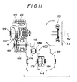
- Fluid pressure is applied to the hydraulic chamber 20 formed within moving cylinder 122 fixed on a back side of the pulley member 16, and a stationary cylinder 124 on which the moving cylinder 122 slides.
- the cylinder 124 is fixed on shaft 12, and the fluid pressure causes the pulley member 16 to move in the axial direction of the shaft 12, whereby groove width 22 is changed.
- fluid pressure is applied to a driven side hydraulic chamber 140 formed within a moving cylinder 136 fixed on a back side of the movable pulley member 28, and a stationary cylinder 138 on which the moving cylinder 136 slides.
- the cylinder 138 is fixed on said driven side shaft 24, and groove width 34 is changed by the fluid pressure in chamber 140.
- a driving-power transmitting mechanism 600 comprises transfer gearing 146 and a differential gear mechanism 148.
- the transfer gearing 146 comprises a transfer drive gear 82 fixed on the driven side shaft 24 of the driven side pulley 6, a transfer driven gear 154 fixed on a rotatable transfer gear shaft 152 engaged with the transfer drive gear 82, a final drive gear 88 fixed on the transfer shaft 152, and a final driven gear 92 engaged with the final drive gear 88.
- the differential gear mechanism 148 comprises a rotatable differential gear casing 160 having fixed thereon said final driven gear 92, and small differential gears 162 and large differential gear 164 placed in the differential gear casing 160.
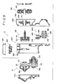
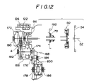
- a transmission case 800 comprises a main case 166, a front case 168 fitted on the side of the main case close to the internal combustion engine (not shown), and a rear case 170 fitted on the side of the main case 166 opposite the internal combustion engine.
- each of the driving side shaft 12, the driven side shaft 24, the transfer gear shaft 152, and the differential gear case 160 is respectively supported, enclosed, and installed in said main case 166 through bearings 64, 174, 176, and 178.
- the other ends of said driving side shaft 12, said driven side shaft 24, the transfer gear shaft 152, and the differential gear case 160 are, through respective bearings 180, 182, 184, and 186, supported, enclosed, and installed in either said front case 168 or said rear case 170.
- An oil pump mechanism 192 includes the oil pump 70 placed in an oil pump housing 108 through a connecting member 106. The oil pump housing 108 is installed in the main case 166.
- a clutch-brake mechanism 94 includes the clutch 68 and the brake 42.
- Reference numeral 122 is a control valve mechanism and 124 is an oil pan enclosing the control valve mechanism 122.
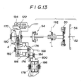
- each of the driving side shaft 12, driven side shaft 24, (rotation shafts of said belt type transmission mechanism), the transfer gear shaft 152, (a rotation shaft of the transfer gear 146), and the differential gear case 160, (a rotation shaft of the differential gear mechanism 148), which compose the driving-power transmitting mechanism 600 is, through the respective bearings 64, 174, 176, and 178, supported, enclosed, and installed by said main case 166.
- the other ends of the driving side shaft 12 and driven side shaft 24 are, through the respective bearings 180 and 182, supported, enclosed, and installed by said rear case 170, and the other ends of the transfer gear shaft 152 and differential gear case 160, or rotation shafts, are, through the respective bearings 184 and 186, supported, enclosed, and installed by said front case 168.
- removing the front case 168 out of the main case 166 provides easy access to the transfer gearing 146 and differential gear mechanism 148 composing the driving-power transmitting mechanism. Meanwhile, in this case, before removing the front case 168, the internal combustion engine side shaft 52, the drive plate 54, and the fluid coupling mechanism 50 should be removed.
- access to the oil pump 70 can be simply achieved by removing the oil pump housing 108 of the oil pump mechanism 192 from the main case 166.
- control valve mechanism 122 as shown in Figure 14, will be easily accessible by removing the oil pan 124.
Landscapes
- Engineering & Computer Science (AREA)
- General Engineering & Computer Science (AREA)
- Mechanical Engineering (AREA)
- General Details Of Gearings (AREA)
- Transmissions By Endless Flexible Members (AREA)
Applications Claiming Priority (8)
| Application Number | Priority Date | Filing Date | Title |
|---|---|---|---|
| JP31262288A JP2906243B2 (ja) | 1988-12-10 | 1988-12-10 | 車両用無段変速機 |
| JP31262188A JP2906242B2 (ja) | 1988-12-10 | 1988-12-10 | 車両用無段自動変速機 |
| JP312621/88 | 1988-12-10 | ||
| JP31262488A JP2906245B2 (ja) | 1988-12-10 | 1988-12-10 | 車両用無段変速機 |
| JP312624/88 | 1988-12-10 | ||
| JP312622/88 | 1988-12-10 | ||
| JP31451588A JPH02159454A (ja) | 1988-12-13 | 1988-12-13 | 車両用無段自動変速機 |
| JP314515/88 | 1988-12-13 |
Publications (3)
| Publication Number | Publication Date |
|---|---|
| EP0373490A2 true EP0373490A2 (fr) | 1990-06-20 |
| EP0373490A3 EP0373490A3 (fr) | 1992-04-01 |
| EP0373490B1 EP0373490B1 (fr) | 1996-02-14 |
Family
ID=27480074
Family Applications (1)
| Application Number | Title | Priority Date | Filing Date |
|---|---|---|---|
| EP89122450A Expired - Lifetime EP0373490B1 (fr) | 1988-12-10 | 1989-12-06 | Boîte de vitesse à rapport de transmission continuement variable |
Country Status (3)
| Country | Link |
|---|---|
| US (1) | US5032108A (fr) |
| EP (1) | EP0373490B1 (fr) |
| DE (1) | DE68925680T2 (fr) |
Cited By (4)
| Publication number | Priority date | Publication date | Assignee | Title |
|---|---|---|---|---|
| EP0763675A3 (fr) * | 1995-09-14 | 1998-01-28 | ZF FRIEDRICHSHAFEN Aktiengesellschaft | Carter de boíte de vitesses automatique |
| EP1083369A3 (fr) * | 1999-09-10 | 2001-07-18 | Mitsubishi Jidosha Kogyo Kabushiki Kaisha | Transmission à variation continue |
| EP1167828A1 (fr) * | 2000-06-30 | 2002-01-02 | Van Doorne's Transmissie B.V. | Transmission à variation continue |
| WO2002004833A1 (fr) * | 2000-07-07 | 2002-01-17 | Scania Cv Ab | Frein hydrodynamique |
Families Citing this family (12)
| Publication number | Priority date | Publication date | Assignee | Title |
|---|---|---|---|---|
| JPH0571622A (ja) * | 1991-09-12 | 1993-03-23 | Honda Motor Co Ltd | 自動変速機の制御装置 |
| JP4752089B2 (ja) * | 2000-05-17 | 2011-08-17 | トヨタ自動車株式会社 | ベルト式無段変速機 |
| EP1489318A4 (fr) * | 2002-03-27 | 2008-10-29 | Nsk Ltd | Roulement a billes pour transmission de type non etagee a courroie |
| JP5564383B2 (ja) | 2009-09-30 | 2014-07-30 | 富士フイルム株式会社 | インプリント用硬化性組成物、パターン形成方法およびパターン |
| JP5671302B2 (ja) | 2009-11-10 | 2015-02-18 | 富士フイルム株式会社 | インプリント用硬化性組成物、パターン形成方法およびパターン |
| WO2011108107A1 (fr) * | 2010-03-04 | 2011-09-09 | トヨタ自動車株式会社 | Transmission à variation continue du type transmission par courroie pour un véhicule |
| JP5753749B2 (ja) | 2010-09-27 | 2015-07-22 | 富士フイルム株式会社 | インプリント用硬化性組成物の製造方法 |
| JP5739185B2 (ja) | 2011-02-15 | 2015-06-24 | 富士フイルム株式会社 | インプリント用硬化性組成物の製造方法 |
| KR101686024B1 (ko) | 2011-04-27 | 2016-12-13 | 후지필름 가부시키가이샤 | 임프린트용 경화성 조성물, 패턴 형성 방법 및 패턴 |
| JP5829177B2 (ja) | 2011-07-12 | 2015-12-09 | 富士フイルム株式会社 | インプリント用硬化性組成物、パターン形成方法およびパターン |
| JP5767615B2 (ja) | 2011-10-07 | 2015-08-19 | 富士フイルム株式会社 | インプリント用下層膜組成物およびこれを用いたパターン形成方法 |
| JP6271483B2 (ja) * | 2015-09-01 | 2018-01-31 | 本田技研工業株式会社 | 変速機の軸受構造 |
Family Cites Families (9)
| Publication number | Priority date | Publication date | Assignee | Title |
|---|---|---|---|---|
| JPS58121349A (ja) * | 1982-01-11 | 1983-07-19 | Nissan Motor Co Ltd | Vベルト式無段変速機の油圧制御装置 |
| JPS5999165A (ja) * | 1982-11-30 | 1984-06-07 | Aisin Warner Ltd | 車両用無段自動変速機の油圧制御装置 |
| JPS59106754A (ja) * | 1982-12-09 | 1984-06-20 | Nissan Motor Co Ltd | Vベルト式無段変速機の油圧制御装置 |
| JPH0715307B2 (ja) * | 1982-12-30 | 1995-02-22 | アイシン・エィ・ダブリュ株式会社 | 車両用無段自動変速機の制御装置 |
| US4526061A (en) * | 1983-03-18 | 1985-07-02 | Aisin-Warner Kabushiki Kaisha | Stepless automatic transmission for motor vehicles |
| DE3372875D1 (en) * | 1983-04-13 | 1987-09-10 | Zahnradfabrik Friedrichshafen | Continuously variable combined transmission |
| FR2553488A1 (fr) * | 1983-10-12 | 1985-04-19 | Renault | Variateur a convertisseur inverseur integre |
| JPH065095B2 (ja) * | 1984-01-27 | 1994-01-19 | トヨタ自動車株式会社 | 自動車用ベルト式無段変速機の油圧制御装置 |
| US4747808A (en) * | 1987-01-08 | 1988-05-31 | Ford Motor Company | System for actuating the displaceable pulley in a continually variable transmission |
-
1989
- 1989-12-06 DE DE68925680T patent/DE68925680T2/de not_active Expired - Fee Related
- 1989-12-06 EP EP89122450A patent/EP0373490B1/fr not_active Expired - Lifetime
- 1989-12-08 US US07/447,868 patent/US5032108A/en not_active Expired - Fee Related
Cited By (6)
| Publication number | Priority date | Publication date | Assignee | Title |
|---|---|---|---|---|
| EP0763675A3 (fr) * | 1995-09-14 | 1998-01-28 | ZF FRIEDRICHSHAFEN Aktiengesellschaft | Carter de boíte de vitesses automatique |
| EP1083369A3 (fr) * | 1999-09-10 | 2001-07-18 | Mitsubishi Jidosha Kogyo Kabushiki Kaisha | Transmission à variation continue |
| US6461269B1 (en) | 1999-09-10 | 2002-10-08 | Mitsubishi Jidosha Kogyo Kabushiki Kaisha | Continuously variable transmission |
| EP1167828A1 (fr) * | 2000-06-30 | 2002-01-02 | Van Doorne's Transmissie B.V. | Transmission à variation continue |
| US6652399B2 (en) | 2000-06-30 | 2003-11-25 | Van Doorne's Transmissie B.V. | Continuously variable transmission |
| WO2002004833A1 (fr) * | 2000-07-07 | 2002-01-17 | Scania Cv Ab | Frein hydrodynamique |
Also Published As
| Publication number | Publication date |
|---|---|
| EP0373490A3 (fr) | 1992-04-01 |
| US5032108A (en) | 1991-07-16 |
| DE68925680D1 (de) | 1996-03-28 |
| DE68925680T2 (de) | 1996-06-27 |
| EP0373490B1 (fr) | 1996-02-14 |
Similar Documents
| Publication | Publication Date | Title |
|---|---|---|
| EP0373490A2 (fr) | Boîte de vitesse à rapport de transmission continuement variable | |
| US7704177B2 (en) | Transmission with continuously variable transmission ratio | |
| EP0141605B1 (fr) | Variateur continu de vitesse | |
| CN100507320C (zh) | 皮带式无级变速器 | |
| JP2837565B2 (ja) | 自動変速機の潤滑機構 | |
| EP0733829A2 (fr) | Transmission à variation continue | |
| KR100240547B1 (ko) | 무단 변속 장치 | |
| GB2058250A (en) | Automotive drive system with continuously variable transmission | |
| EP0239124B1 (fr) | Dispositif de transmission de puissanceà rapport de transmission variable | |
| US5512021A (en) | Variable ratio transmission | |
| EP0289025A1 (fr) | Variateur continu de vitesse à courroie et poulies | |
| JP2906245B2 (ja) | 車両用無段変速機 | |
| JPH1163176A (ja) | 遊星歯車装置の潤滑油供給構造 | |
| US4550629A (en) | Continuously variable speed transmission for motor vehicles | |
| JP3571607B2 (ja) | ベルト式無段変速機 | |
| EP0937911B1 (fr) | Transmission à changement de vitesses continue | |
| KR19990021823A (ko) | 차량용 무단 변속 장치 | |
| JPH04285354A (ja) | 車両用変速装置 | |
| KR950007256B1 (ko) | 무단자동변속장치 | |
| JP4035423B2 (ja) | 変速機 | |
| GB2180022A (en) | Variable speed accessory drive | |
| JP2906242B2 (ja) | 車両用無段自動変速機 | |
| JPS60252870A (ja) | ベルト式無段変速装置を備えた変速機 | |
| KR100328382B1 (ko) | 무단 변속장치 | |
| KR0183220B1 (ko) | 차량용 무단 변속장치 |
Legal Events
| Date | Code | Title | Description |
|---|---|---|---|
| PUAI | Public reference made under article 153(3) epc to a published international application that has entered the european phase |
Free format text: ORIGINAL CODE: 0009012 |
|
| 17P | Request for examination filed |
Effective date: 19891206 |
|
| AK | Designated contracting states |
Kind code of ref document: A2 Designated state(s): DE FR GB |
|
| PUAL | Search report despatched |
Free format text: ORIGINAL CODE: 0009013 |
|
| AK | Designated contracting states |
Kind code of ref document: A3 Designated state(s): DE FR GB |
|
| RAP1 | Party data changed (applicant data changed or rights of an application transferred) |
Owner name: SUZUKI MOTOR CORPORATION |
|
| 17Q | First examination report despatched |
Effective date: 19930916 |
|
| GRAA | (expected) grant |
Free format text: ORIGINAL CODE: 0009210 |
|
| AK | Designated contracting states |
Kind code of ref document: B1 Designated state(s): DE FR GB |
|
| REF | Corresponds to: |
Ref document number: 68925680 Country of ref document: DE Date of ref document: 19960328 |
|
| ET | Fr: translation filed | ||
| PLBE | No opposition filed within time limit |
Free format text: ORIGINAL CODE: 0009261 |
|
| STAA | Information on the status of an ep patent application or granted ep patent |
Free format text: STATUS: NO OPPOSITION FILED WITHIN TIME LIMIT |
|
| 26N | No opposition filed | ||
| PGFP | Annual fee paid to national office [announced via postgrant information from national office to epo] |
Ref country code: GB Payment date: 19971127 Year of fee payment: 9 |
|
| PGFP | Annual fee paid to national office [announced via postgrant information from national office to epo] |
Ref country code: FR Payment date: 19971209 Year of fee payment: 9 |
|
| PGFP | Annual fee paid to national office [announced via postgrant information from national office to epo] |
Ref country code: DE Payment date: 19971212 Year of fee payment: 9 |
|
| PG25 | Lapsed in a contracting state [announced via postgrant information from national office to epo] |
Ref country code: GB Free format text: LAPSE BECAUSE OF NON-PAYMENT OF DUE FEES Effective date: 19981206 |
|
| GBPC | Gb: european patent ceased through non-payment of renewal fee |
Effective date: 19981206 |
|
| PG25 | Lapsed in a contracting state [announced via postgrant information from national office to epo] |
Ref country code: FR Free format text: LAPSE BECAUSE OF NON-PAYMENT OF DUE FEES Effective date: 19990831 |
|
| REG | Reference to a national code |
Ref country code: FR Ref legal event code: ST |
|
| PG25 | Lapsed in a contracting state [announced via postgrant information from national office to epo] |
Ref country code: DE Free format text: LAPSE BECAUSE OF NON-PAYMENT OF DUE FEES Effective date: 19991001 |