EP0375094A2 - Verfahren und Vorrichtung zum Warmbandwalzen - Google Patents
Verfahren und Vorrichtung zum Warmbandwalzen Download PDFInfo
- Publication number
- EP0375094A2 EP0375094A2 EP19890250129 EP89250129A EP0375094A2 EP 0375094 A2 EP0375094 A2 EP 0375094A2 EP 19890250129 EP19890250129 EP 19890250129 EP 89250129 A EP89250129 A EP 89250129A EP 0375094 A2 EP0375094 A2 EP 0375094A2
- Authority
- EP
- European Patent Office
- Prior art keywords
- strip
- stand
- thickness
- hot strip
- supply
- Prior art date
- Legal status (The legal status is an assumption and is not a legal conclusion. Google has not performed a legal analysis and makes no representation as to the accuracy of the status listed.)
- Granted
Links
Images


Classifications
-
- B—PERFORMING OPERATIONS; TRANSPORTING
- B21—MECHANICAL METAL-WORKING WITHOUT ESSENTIALLY REMOVING MATERIAL; PUNCHING METAL
- B21B—ROLLING OF METAL
- B21B37/00—Control devices or methods specially adapted for metal-rolling mills or the work produced thereby
- B21B37/48—Tension control; Compression control
- B21B37/50—Tension control; Compression control by looper control
-
- B—PERFORMING OPERATIONS; TRANSPORTING
- B21—MECHANICAL METAL-WORKING WITHOUT ESSENTIALLY REMOVING MATERIAL; PUNCHING METAL
- B21B—ROLLING OF METAL
- B21B37/00—Control devices or methods specially adapted for metal-rolling mills or the work produced thereby
- B21B37/16—Control of thickness, width, diameter or other transverse dimensions
- B21B37/165—Control of thickness, width, diameter or other transverse dimensions responsive mainly to the measured thickness of the product
-
- B—PERFORMING OPERATIONS; TRANSPORTING
- B21—MECHANICAL METAL-WORKING WITHOUT ESSENTIALLY REMOVING MATERIAL; PUNCHING METAL
- B21B—ROLLING OF METAL
- B21B37/00—Control devices or methods specially adapted for metal-rolling mills or the work produced thereby
- B21B37/16—Control of thickness, width, diameter or other transverse dimensions
- B21B37/22—Lateral spread control; Width control, e.g. by edge rolling
-
- B—PERFORMING OPERATIONS; TRANSPORTING
- B21—MECHANICAL METAL-WORKING WITHOUT ESSENTIALLY REMOVING MATERIAL; PUNCHING METAL
- B21B—ROLLING OF METAL
- B21B37/00—Control devices or methods specially adapted for metal-rolling mills or the work produced thereby
- B21B37/72—Rear end control; Front end control
-
- B—PERFORMING OPERATIONS; TRANSPORTING
- B21—MECHANICAL METAL-WORKING WITHOUT ESSENTIALLY REMOVING MATERIAL; PUNCHING METAL
- B21B—ROLLING OF METAL
- B21B2261/00—Product parameters
- B21B2261/02—Transverse dimensions
- B21B2261/06—Width
-
- B—PERFORMING OPERATIONS; TRANSPORTING
- B21—MECHANICAL METAL-WORKING WITHOUT ESSENTIALLY REMOVING MATERIAL; PUNCHING METAL
- B21B—ROLLING OF METAL
- B21B2271/00—Mill stand parameters
- B21B2271/02—Roll gap, screw-down position, draft position
Definitions
- the invention relates to a method and a device for regulating hot strip rolling according to the preambles of claims 1 and 14.
- Hot strip rolling on modern continuous rolling mills is intended to set the finished geometry of the strip, which is predetermined within narrow tolerances, in addition to influencing the technological characteristics of the strip through controlled thermomechanical rolling.
- rolling mills can be equipped with strip tension control by adjusting the speed and / or loop lifters, which, in addition to a roll gap control and rolling force measurement and strip thickness measurement, enable control of the rolling mill (Iron and Steel Engineer, 9/84, pages 45-51) .
- This publication also describes in detail the functioning of a load-dependent control of the roll gap height (bearing play and stand expansion compensation) and the possibility of dispensing with loop lifters between the first stands of the finishing relay, the loop lifters being controlled by a minimum tension control due to known rolling forces and motor torques and the resulting change in speed Work rolls to be replaced.
- the mass flows at the inlet and outlet of the finished scale are the same.
- the parameters of width, thickness, speed and weight of the strip change during the course of the method.
- the parameters can be measured directly on the rolling mill.
- the weight as a function of the rolling temperature and the type of material can only be recorded as an implicit statistical variable during rolling.
- the change in weight of approx. 0.1% during hot rolling is negligible.
- the invention takes into account the knowledge that the strip supply between the stands has to be regulated in order to achieve a stable operating state during hot rolling.
- the spreading that occurs during rolling or constriction of the strip either remains constant or changes in a known manner, so that it can be used as a factor in a material flow calculation.
- the rolling mill If you think of the rolling mill as a controlled system, to which the control loops for the target guide values of speed and idle roll gap or load roll gap are assigned, you get the rolling forces, the rolling moments, the loop lifter angles, the sliver thickness and the slowing speed as important output signals.
- the speeds of the rolls and the nip feeds are available as manipulated variables. The speeds influence the loop lifter angle and the material flow speed; the roll gap feed also influences the loop lifter angles, the material flow speed and the resulting strip thicknesses.
- the variation in the resistance to deformation of the strip as a function of material type and temperature acts primarily as a disturbance variable. This also includes so-called skidmarks (rail shadows) from slab heating. Irregularities in the slitting or roughing of slabs, as well as the lack of side upsetting units in the roughing mill, also cause strip geometry fluctuations.
- the usual guide setpoint for the position control loop "empty rolling gap" after the strip has entered the first stand is replaced by actuating signals from the individual strip supply controllers.
- the strip supply controllers then control the mass flow, arithmetically the volume flow, in the finishing line for the hot strip section with the exception of the strip end.
- the well-known automatic load gap control device replaces the strip supply control.
- the current actual values of the strip thickness or the roll gap are taken over bumplessly as setpoints in order to prevent the control loops from settling again.
- Different indicators are used as control variables for the individual band supply regulators, which act primarily independently of one another.
- a setpoint deviation or the actual value for a specific strip supply of a section of the finished scale provides either the strip tension determination or the angle measurement of the loop lift deflection.
- the regulation of the first scaffold differs from this.
- the thickness and the speed of the incoming strip can be measured - assuming the permissible assumption that there is currently a constant strip width - a mass flow equivalent.
- the Roll gap are set on the first stand so that the mass flow, mathematically simplified as a product of thickness and speed, remains constant due to backflow of the material.
- the loop regulation between the front stands can be replaced by tension regulation of the belt, a relatively good flatness of the belt is achieved. This enables the use of a thickness measuring system behind the first stand and thus the additional possibility of regulating the thickness of the hot strip on the first stand.
- the method of radio transmission of strain gauge torque measurements can be used according to the invention.
- the strain gauge method directly records the torsional moments without loss the work roll shaft. The results are then available without delay for the train calculation due to the radio transmission.
- the selection of the most suitable indicators which indicate a variation of the mass flow or band supply in front of the scaffolding, is made according to their most favorable properties with regard to the conditions: lowest investment costs, greatest control speed and best effect on the band geometry. It has proven to be advantageous to keep the sling lifter angle as constant as possible, because this prevents difficulties during adjustment that result from the non-angular force effect of the sling lifter on the belt.
- a thickness regulation supplementing the strip supply regulation can be used according to the invention.
- the aim is to achieve maximum deviations from the target strip thickness of less than 0.05 mm.
- the actual thickness value measured for example, with a radiation measuring device - gamma emitter cesium 137 - is fed to a thickness controller, which can optionally generate two control signals correlating to the extent of the deviation from the target thickness.
- a change in thickness can be recorded as a trend in the thickness measuring device behind the finished scale and thus by changing the speed trend (temperature speed-up) of the work rolls between two Scaffold groups of the finished batch locally the strip supply is increased or decreased with the effect that the strip supply controller intervenes and changes the strip thickness.
- a correction signal - delayed to adapt to the higher control speed of the roll gap control circuit - can be sent to the roll gap controller of the stand concerned, so that the strip supply actually does not change.
- the bandwidth is regulated during the last stitch acceptance by measuring the bandwidth and comparing the measured values in a width controller with nominal values for the bandwidth. As soon as setpoint deviations arise, a new strip tension is calculated from this according to the predefined calculation scheme, which must lead to a change in the strip width before the last stitch acceptance.
- the width controller sends a signal to the strip supply controller of the last stand, which in turn generates the change in tension by adjusting the roll gap.
- the thickness controller must also receive a feedforward control.
- the last stitch acceptance must be designed in such a way that it is greater in percentage than the fluctuation in the bandwidth to be corrected.
- the width control works if the bandwidth is measured after the last stitch decrease.
- the time delay in the control makes it seem more favorable to measure the bandwidth before the penultimate stitch acceptance or to use two measuring devices so that the width controller can already be controlled.
- the same method can also be used for width control by changing the tension of the belt between the first stands, provided that appropriate width measuring and control devices are used there.
- the diagram in FIG. 1 shows the change in the specific tensile stress in the hot strip 10 over the angular position (looper angle) of a loop lifter (looper) at 4 to 10 bar fluid pressure (looper pressure) of the lifting cylinder of the loop lifter. Every change in the angle of the sling lifter causes tension fluctuations in the belt. With the band supply control and the band tension changes are significantly less than with the conventional loop control.
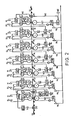
- Fig. 2 shows the conditions on the finishing line of a rolling mill for hot strip 10 with seven roll stands 1 ... 7, four swiveling loop lifters 12 ... 15 and a vertically adjustable and lockable deflection roller 16 with force measuring device 9.
- the drives, measuring devices and actuators are Not all are shown for the sake of clarity.
- Each scaffold has a belt supply controller BVR and an additional thickness controller DR is installed on the last scaffold.
- each stand also has a position controller PR and an automatic load roll gap control AGC, which receives the roll gap h currently calculated from roll force f and the displayed position s of the rolls from a roll gap computer HR.
- All setpoints for the roll speeds NL are predefined by a master setpoint calculator (not shown) and correspondingly during the rolling Desired pass schedule ramped and the desired temperature speed-up tends to increase.
- Speed controllers DNR ensure that the speeds comply with their current setpoints N 1 ... N 7.
- the setpoints of the roll gap heights SL are also specified by the master setpoint computer before the start of the roll. They have to be readjusted continuously during rolling in order to adapt to the material flow or strip supply.
- the necessary supply signals delta S are provided by the belt supply controller BVR.
- Each belt supply controller BVR obtains its actual value from the piece of belt entering the respective scaffolding 1 ... 7, while its setpoint SL is constant.
- the physical quantity used as the actual value is in all cases a measure of the supply of strip volume (mass supply) in front of the stand and after the previous stand.
- the belt supply controller BVR thus regulates a constant belt supply between stands 1 ... 7.
- the nominal thickness H Z is used as the target value and the current thickness h Z as the actual value. Strictly speaking, this band supply regulator BVR is only a thickness regulator. It can be controlled by the thickness h 0.
- loop lifter angles a12 ... a15 serve as the actual value for the belt supply regulator BVR. Each angle is a measure of the tape length in stock.
- the tensile force z 1 or z 6 in the incoming strip section is used as the actual value for the respective strip supply controller BVR.
- the tensile force indicates the tape supply, the is available when the material deforms plastically. With a low pulling force the stock is larger than with a large pulling force.
- the methods for determining the tensile forces z 1 and z 6 are very different for the stands 2 and 7.
- the tensile force z 1 in front of the stand 2 is determined from the measured values of the rolling force f and the torque m of the work roll shaft in the stand 1 before and after the run-in of the belt 10 in the scaffold 2 calculated in the belt tension calculator ZB.
- the torque m is determined by strain gauges, not shown, and transmitted by radio to the strip tension computer ZB.
- a deflection roller 16 equipped with a force sensor 9 is used. For this purpose, it is hydraulically moved vertically into its target position immediately after tapping the scaffold 7 and blocked there.
- the procedure for finishing a hot strip is regulated as follows: After the strip 10 has entered the stand 1, the thicknesses h 0 and h Z are determined using the thickness gauges DO, DZ and the torque m and the rolling force f or the quotient m / f. The thickness is sent to the BVR, which takes over the further regulation on scaffold 1. After the belt 10 has entered the stand 2, the measured values m and f and their quotient change. The strip tension computer ZB determines the strip tension or tensile force z 1 from the change and thus acts on the strip supply controller BVR on stand 2, which subsequently controls the load roll gap height s 2. The check is done thereby via the position controller PR.
- the loop lifter 12 After the stand 3 has been tapped, the loop lifter 12 is moved into the desired position; a setpoint deviation of a 12 leads to a change in the load roll gap height s 3 on the stand 3 by the BVR strip supply controller.
- the deflection roller 16 After tapping the Scaffolding 7, the deflection roller 16 is moved into the desired position and locked there.
- Force sensor 9 determines the tensile force z 6 and thus acts on the strip supply regulator BVR on stand 7. All strip supply regulators BVR ensure a constant strip supply between the stands by possibly changing the roll gap, with the result that the loop lifters 12 ... 15 only in narrow spaces Swing borders. As a result, with "correct" presetting of the strip thickness HZ, very small deviations to be corrected are achieved, which are then corrected by the very fast roll gap adjustment.
- the desired thickness tolerances behind the finished scale can be exceeded due to faults, for example as a result of temperature or thickness differences in the preliminary strip. This is determined by a final thickness measurement.
- the strip supply control is supplemented by a control of the exit thickness h E.
- the mode of operation of the thickness control with the aid of the thickness controller DR has been derived from the following consideration:
- the thickness h of the strip 10 emerging from the roll gap is obtained, in which the entry thickness into the stand is divided by the extension factor by which the Band length increased.
- the width of the band 10 is negligible.
- h 0 is the entry thickness
- h E the exit thicknesses
- v 0 the entry speed in stand 1
- v 7 the exit speed from stand 7.
- the quotient v 0 / v 7 is the reciprocal extension factor.
- the variables h 0, v 0 and v 7 are suitable according to the equation. However, these three variables act on the exit thickness h E at different speeds in this control loop.
- the equation only describes the steady state equilibrium; the dynamic behavior is different.
- the entry thickness h 0 has the slowest effect on the exit thickness h E.
- the running time of the belt 10 through all the stands has a delaying effect here.
- the influence of speed v 0 is at least ten times faster. Its effect is only delayed by the swinging in of the six consecutive band supply control loops.
- the exit thickness h E is most rapidly influenced by the speed v 7, because only the last strip supply control loop has to settle here.
- the speed v 7 is therefore best suited as an actuator for a thickness control circuit.
- the thickness controller DR supplies a correction signal delta v 7, which is added positively or negatively to the speed specified by the computer via the roll speed N 7 . Instead, could you can also change the temperature speed-up for frameworks 1 to 6 by the value delta v 7.
- the product calculated from the measured values h 0 and v 0 can be regulated to a constant value by the belt supply controller of stand 1 at the entrance of the rolling mill, or, as shown in FIG. 2, the Product h Z x v1 can be kept constant by keeping v1 approximately constant by the speed controller and h Z by the belt supply controller of the first stand.
- the measurement of the thickness values h 0 and h Z could therefore also be replaced according to FIG. 3 by measuring the current thickness h 0 with a thickness meter DO and the current entry speed v 0, without changing the control principle.
- the tape supply controller BVR can of course only deliver their control signals delta s for the position controller PR as long as the tape supply indicators flow from the respective measuring sensors.
- the corresponding BVR strip supply controller must be deactivated.
- the load roll gap control AGC acted upon by the rolling force f takes over the further regulation of the roll gap in a manner known per se.
- the current roll gap value is accepted without bumps. From the illustration 2 shows that the switchover from stand 2 to AGC takes place as soon as the belt 10 leaves the stand 1, because the belt supply controller BVR then no longer receives any tension values z 1. This applies analogously to frameworks 3 to 6, since the loop lifters have to be deactivated; correspondingly, no true force effect can be measured for the scaffold 7 on the deflection roller 16.
- FIG. 4 shows the possibility of optimizing the course of the process by additionally providing the finished scale with a width regulation.
- the width meter 11 records the bandwidth b 7 after the last stitch acceptance in the frame 7.
- the measured value is compared with the nominal width BE in the width controller BR.
- the width controller BR calculates a control signal delta Z and thus acts on the belt supply controller BVR of the stand 7. If the bandwidth b 7 is too large, the signal delta Z will result in a tension value being applied to the controller BVR with the tension tension z 6 , which then detects an excessively large supply of strip and opens the roll gap on stand 7 by the value delta S, with the result that the tensile stress in the strip is increased and the strip width is reduced.
- the control effect is faster if, as shown, a further width meter 8 in front of the scaffold 6 pre-controls the current bandwidth BR, so that width differences are true to location Loss of time can be corrected by settling the control loop.
- the process sequence on the rolling mill can be optimally controlled and the effort for loop lifters, measuring devices and control systems is kept within limits.
- Tests with this control system have shown an improvement in the tolerances for the strip thickness h E to values of plus / minus 0.02 mm to the target thickness of 1.5 mm.
Landscapes
- Engineering & Computer Science (AREA)
- Mechanical Engineering (AREA)
- Control Of Metal Rolling (AREA)
- Metal Rolling (AREA)
Abstract
Description
- Die Erfindung betrifft ein Verfahren und eine Vorrichtung zum Regeln des Warmbandwalzens gemäß den Oberbegriffen der Ansprüche 1 und 14.
- Durch Warmbandwalzen auf modernen kontinuierlichen Walzstraßen mit meist fünf oder mehr Walzgerüsten in der Fertigstaffel soll neben der Beeinflussung der technologischen Kennwerte des Bandes durch geregeltes thermomechanisches Walzen eine in engen Toleranzen vorbestimmte Fertiggeometrie des Bandes eingestellt werden.
- Bei gegebenem Einlaufquerschnitt und bekannter Einlaufgeschwindigkeit eines Bandes sowie erwünschtem Auslaufquerschnitt des Bandes wird dessen zwangsläufige Streckung während des Walzens durch von Gerüst zu Gerüst kaskadenartig steigende Walzgeschwindigkeit und damit steigende Walzendrehzahl in Abhängigkeit von der in der Regel degressiv gestuften Stichabnahme kompensiert. Mit zunehmender Verweilzeit kühlt das Band vor und in der Fertigstaffel aus; daher wird die Basiswalzgeschwindigkeit und somit die Wärmeabgabe aufgrund erhöhter Formänderungsarbeit stetig gesteigert, um die metallurgisch wichtige Endwalztemperatur annähernd konstant zu halten (Temperatur-speed-up). Diese Vorgaben für die Geschwindigkeitsverhältnisse und die rechnerischen Leerwalzspalthöhen der Einzelgerüste gibt ein Solleitwertrechner vor.
- Die Bandgeschwindigkeit und die Walzenumfangsgeschwindigkeit sind aber nur in der Fließscheide gleich. Das Material erfährt eine Vor- und Nacheilung im Walzspalt. Um dadurch entstehende Probleme zu vermeiden, können Walzstraßen mit einer Bandzugregelung durch Drehzahlanpassung und/oder Schlingenheber ausgerüstet sein, die zusätzlich zu einer Walzspaltkontrolle und Walzkraftmessung sowie Banddickenmessung eine Steuerung der Walzstraße ermöglichen (Iron and Steel Engineer, 9/84, Seite 45-51). In dieser Veröffentlichung ist außerdem detailliert die Funktionsweise einer belastungsabhängigen Regelung der Walzspalthöhe (Lagerspiel- und Gerüstdehnungskompensation) und die Möglichkeit des Verzichtes auf Schlingenheber zwischen den ersten Gerüsten der Fertigstaffel dargestellt, wobei die Schlingenheber durch eine Minimalzugregelung aufgrund bekannter Walzkräfte und Motormomente und daraus resultierender Drehzahländerung der Arbeitswalzen ersetzt werden.
- Es ist auch schon versucht worden, eine größtmögliche Genauigkeit der Banddicke zu erreichen, indem für die aus dem Stichplan resultierenden Walzspalthöhen jedes Gerüstes eine Korrektur der gemessenen Dickentoleranzen durch Verstellen des Lastwalzspaltes während des Walzens zu realisieren (DE-OS 36 37 043) oder den gesamten Materialstrom durch eine Walzstraße durch eine Minimalzugregelung allein mittels Drehzahlkorrektur der Arbeitswalzen sowie eine Dickenregelung am ersten Gerüst zu beeinflussen (DE-OS 27 21 973). Ein Drehzahlregelkreis ist aber wegen der großen Ansprechzeit aufgrund der Schwungmassen der Walzen sehr träge.
- Von daher ist es Aufgabe der Erfindung, ein Verfahren und eine Vorrichtung zum Regeln des Warmwalzens von Bändern in der Fertigstaffel einer Walzstraße vorzuschlagen, die ein sehr genaues Einstellen der Banddicke ermöglichen bei relativ geringem Aufwand für eine praxisnahe Regeloptimierung.
- Die Aufgabe wird erfindungsgemäß durch die Ansprüche 1 und 14 gelöst. Vorteilhafte Ausgestaltungen der Erfindung sind in den Unteransprüchen erfaßt.
- Verfahrensbedingt sind die Massenströme am Einlauf und Auslauf der Fertigstaffel gleich groß. In der bekannten Kontinuitätsgleichung ändern sich jedoch während des Verfahrensablaufs die Parameter Breite, Dicke, Geschwindigkeit und Wichte des Bandes. Mit Ausnahme der Wichte lassen sich die Parameter an der Walzstraße direkt messen. Die Wichte als Funktion von Walztemperatur und Materialart wird nur als implizite statistische Größe während des Walzens erfaßbar. Die Wichteänderung von ca. 0,1 % während des Warmwalzens ist vernachlässigbar.
- Die Erfindung berücksichtigt die Erkenntnis, daß der Bandvorrat zwischen den Gerüsten geregelt werden muß, um einen stabilen Betriebszustand beim Warmwalzen zu erreichen.
- Außerdem wird berücksichtigt, daß zumindest in erster Näherung die während des Walzens auftretende Breitung oder Einschürung des Bandes entweder konstant bleibt oder sich in bekannter Weise ändert, somit in eine Materialflußrechnung als Faktor rechnerisch einfließen kann.
- Wenn man sich die Walzstraße als Regelstrecke, der die Regelkreise für die Soll-Leitwerte Drehzahlen und Leerwalzspalte beziehungsweise Lastwalzspalte zugeordnet sind, vorstellt, erhält man als wichtige Ausgangssignale die Walzkräfte, die Walzmomente, die Schlingenheberwinkel, die auslaufende Banddicke und die Auslaufgeschwindigkeit. Als Stellgrößen stehen die Drehzahlen der Walzen und die Walzspaltzustellungen zur Verfügung. Die Drehzahlen beeinflussen die Schlingenheberwinkel und die Materialflußgeschwindigkeit; die Walzspaltzustellung beeinflußt ebenfalls die Schlingenheberwinkel, die Materialflußgeschwindigkeit sowie die resultierenden Banddicken. Als Störgröße wirkt in erster Linie in dieser Regelstrecke die Variation der Formänderungsfestigkeit des Bandes als Funktion von Materialart und Temperatur. Dazu gehören auch sogenannte Skidmarks (Schienenschatten) aus der Brammenerwärmung. Auch Unregelmäßigkeiten beim Längsteilen oder Vorwalzen von Brammen sowie fehlende seitliche Stauchaggregate in der Vorwalzstraße lassen Bandgeometrieschwankungen entstehen.
- Da genügend Stellgrößen zur Beeinflussung des Regelsystems zur Verfügung stehen, kann primär auf eine Drehzahlverstellung der Walzen verzichtet werden. Eine Walzspalthöhenänderung kann wesentlich schneller geschehen als eine Änderung der Walzendrehzahl, so daß sich die Zustellung des Walzenspaltes als Stellgröße für eine Bandvorratsregelung und zur Korrektur der Banddicke an den Gerüsten am besten eignet.
- Erfindungsgemäß wird dazu der übliche Leit-Sollwert für den Positionsregelkreis "Leer-Walzspalt" nach Einlauf des Bandes in das erste Gerüst gerüstweise durch Stellsignale der einzelnen Bandvorratsregler abgelöst. Die Bandvorratsregler steuern in der Folge den Massenfluß, rechnerisch den Volumenfluß, in der Fertigstaffel für die Warmbandstrecke mit Ausnahme des Bandendes. Kurz bevor das Bandende ein Gerüst erreicht, löst die bekannte automatische Lastwalzspaltkontrolleinrichtung die Bandvorratsregelung wieder ab. Bei diesem Umschaltverfahren werden die momentanen Istwerte der Banddicke beziehungsweise der Walzspalte stoßfrei als Sollwerte übernommen, um ein erneutes Einschwingen der Regelkreise zu vermeiden. Für die einzelnen primär unabhängig voneinander wirkenden Bandvorratsregler werden unterschiedliche Indikatoren als Regelgröße verwendet.
- Eine Sollwertabweichung beziehungsweise den Istwert für einen bestimmten Bandvorrat eines Abschnittes der Fertigstaffel liefert entweder die Bandzugermittlung oder die Winkelmessung des Schlingenheberausschlages.
- Davon unterscheidet sich die Regelung des ersten Gerüstes. Hier kann die Dicke und die Geschwindigkeit des einlaufenden Bandes - unter der zulässigen Annahme, daß momentan eine konstante Bandbreite vorliegt - also ein Massenstromäquivalent gemessen werden. Bei Änderung der Dicke oder Geschwindigkeit des Bandes kann der Walzspalt so am ersten Gerüst eingestellt werden, daß der Massenstrom, rechnerisch vereinfacht als Produkt aus Dicke und Geschwindigkeit, durch Rückstau des Materials konstant bleibt.
- Da erfindungsgemäß die Schlingenregelung zwischen den vorderen Gerüsten durch eine Zugregelung des Bandes ersetzt werden kann, erreicht man eine relativ gute Planlage des Bandes. Dies ermöglicht den Einsatz einer Dickenmeßanlage hinter dem ersten Gerüst und damit die zusätzliche Möglichkeit der Dickenregelung des Warmbandes am ersten Gerüst.
- Es hat sich in Versuchen überraschend die Annahme bestätigt, daß man auf teure schwenkbare Schlingenheber zwischen den ersten Gerüsten ganz verzichten kann und den Schlingenheber vor dem letzten oder mehreren der letzten Gerüste als einfache, vertikal verfahrbare Umlenkrolle gestalten kann, wenn man die erfindungsgemäße Verfahrenskonzeption anwendet. Die Wirksamkeit der vorderen Schlingenheber ist sowieso durch die Bandsteifigkeit relativ gering, und der gleiche Effekt kann durch ein aus gemessenen Wellenmomenten der Arbeitswalzen und Walzkräften errechneten Bandzug mittels Bandvorratsregelung des folgenden Gerüstes erreicht werden.
- Bei der Ermittlung der Bandzugspannung zwischen den Gerüsten kann erfindungsgemäß die Methode der Funkübertragung von DMS-Drehmomentmessungen angewendet werden. Gegenüber der Momentermittlung aus den Strom- und Spannungswerten der Walzenantriebe erfaßt die DMS-Methode verlustfrei die Torsionsmomente direkt an der Arbeitswalzenwelle. Die Ergebnisse stehen dann durch die Funkübertragung verzögerungsfrei für die Zugberechnung zur Verfügung.
- Die Auswahl der geeignetsten Indikatoren, die eine Variation des Massenflusses bzw. Bandvorrates vor dem Gerüst anzeigen, wird jeweils nach deren günstigsten Eigenschaften hinsichtlich der Bedingungen getroffen: geringster Aufwand an Investitionen, größte Regelgeschwindigkeit und beste Wirkung auf die Bandgeometrie. Als vorteilhaft hat es sich erwiesen, den Schlingenheberwinkel möglichst konstant zu halten, weil dadurch Schwierigkeiten, die aus der nicht winkelproportionalen Kraftwirkung der Schlingenheber auf das Band resultieren, bei der Ausregelung verhindert werden.
- Sollte die Banddicke hinter der Fertigstaffel trotz Bandvorratsregelung noch außerhalb der gewünschten Toleranzen liegen, kann erfindungsgemäß eine die Bandvorratsregelung ergänzende Dickenregelung eingesetzt werden. Angestrebt werden maximale Abweichungen von der Sollbanddicke von kleiner 0,05 mm. Dazu wird der beispielsweise mit einem Durchstrahlungsmeßgerät - Gammastrahler Caesium 137 - gemessene Dicken-Istwert einem Dickenregler zugeführt, der gegebenenfalls zwei Stellsignale korrelierend zu dem Maß der Abweichung von der Solldicke erzeugen kann.
- Eine Dickenänderung läßt sich als Trend im Dickenmeßgerät hinter der Fertigstaffel erfassen und somit kann durch Änderung des Drehzahltrends (Temperatur-speed-up) der Arbeitswalzen zwischen zwei Gerüstgruppen der Fertigstaffel örtlich der Bandvorrat erhöht oder verringert werden mit dem Effekt, daß der Bandvorratsregler eingreift und die Banddicke ändert. Gleichzeitig kann ein Korrektursignal - zeitverzögert zur Anpassung an die höhere Regelgeschwindigkeit des Walzspaltregelkreises - an den Walzspaltregler des betroffenen Gerüstes geleitet werden, damit sich der Bandvorrat tatsächlich nicht ändert.
- Eine noch genauere Steuerung der Banddicke kann erreicht werden, wenn die näherungsweise rechnerisch in die Volumenflußregelung bzw. Massenstromregelung einbezogene Bandbreitenänderung ebenfalls regelungstechnisch weitgehend kompensiert wird. Dazu wird erfindungsgemäß bei der letzten Stichabnahme eine Regelung der Bandbreite vorgenommen, in dem die Bandbreite gemessen und die Meßwerte in einem Breitenregler mit Sollwerten für die Bandbreite verglichen werden. Sobald Sollwertabweichungen entstehen, wird daraus nach vorgegebenem Rechenschema eine neue Bandzugspannung errechnet, die zur Breitenänderung des Bandes vor der letzten Stichabnahme führen muß. Dazu gibt der Breitenregler ein Signal an den Bandvorratsregler des letzten Gerüstes, der dann wiederum die Zugspannungsänderung durch Verstellung des Walzspaltes erzeugt. Mit dieser schnellen Regelung lassen sich örtliche Breitenschwankungen, die u. a. aus Skidmarks (Schienenschatten bei der Brammenerwärmung) herrühren können, korrigieren, ohne daß die langsamere Dickenregelung für Kompensation sorgt.
- Ansonsten muß der Dickenregler ebenfalls eine Störgrößenaufschaltung erhalten.
- Die letzte Stichabnahme muß für diese Regelung so gestaltet werden, daß sie prozentual größer ist als die auszuregelnde Bandbreitenschwankung.
- Prinzipiell funktioniert die Breitenregelung, wenn die Bandbreite hinter der letzten Stichabnahme gemessen wird. Der Zeitverzug bei der Regelung läßt es jedoch günstiger erscheinen, die Bandbreite schon vor der vorletzten Stichabnahme zu messen oder zwei Meßgeräte einzusetzen, damit der Breitenregler schon vorgesteuert werden kann. Das gleiche Verfahren läßt sich auch für eine Breitenregelung durch Änderung der Zugspannung des Bandes zwischen den ersten Gerüsten durchführen, sofern dort entsprechende Breitenmeß- und Regelgeräte eingesetzt werden.
- Anhand schematischer Zeichnungen soll die Erfindung näher erläutert werden. Es zeigen
- Fig. 1 die Kraftwirkung eines Schlingenhebers,
- Fig. 2 eine erfindungsgemäße Regelung für eine Fertigstaffel als Blockschaltbild.
- Fig. 3 eine erfindungsgemäße Regelung am ersten Gerüst einer Fertigstaffel als Blockschaltbild und
- Fig. 4 eine weitere erfindungsgemäße Regelung an den letzten Gerüsten einer Fertigstaffel als Blockschaltbild.
- Das Diagramm in Fig. 1 zeigt die Änderung der spezifischen Zugspannung im Warmband 10 über der Winkelstellung (Looperwinkel) eines Schlingenhebers (Looper) bei 4 bis 10 bar Fluiddruck (Looperdruck) des Hubzylinders des Schlingenhebers. Jede Winkeländerung des Schlingenhebers verursacht also Zugschwankungen im Band. Bei der Bandvorratsregelung und sind die Bandzugänderungen wesentlich geringer als bei der konventionellen Schlingenregelung.
- Fig. 2 zeigt die Verhältnisse an der Fertigstaffel einer Walzstraße für Warmbreitband 10 mit sieben Walzgerüsten 1...7, vier schwenkbaren Schlingenhebern 12...15 und einer vertikal verstellbaren und arretierbaren Umlenkrolle 16 mit Kraftmeßeinrichtung 9. Die Antriebe, Meßgeräte und Stellorgane sind der besseren Übersicht wegen nicht alle dargestellt. Jedes Gerüst verfügt über einen Bandvorratsregler BVR und am letzten Gerüst ist zusätzlich ein Dickenregler DR installiert. Gemäß dem Stand der Technik verfügt jedes Gerüst außerdem über einen Positionsregler PR und eine automatische Last-Walzspaltkontrolle AGC, der von einem Walzspaltrechner HR die aktuell aus Walzkraft f und der angezeigten Position s der Walzen errechneten Walzspalte h erhält.
- Bei der folgenden Funktionsbeschreibung sollen große Buchstaben Sollwerte und kleine Buchstaben Istwerte kennzeichnen.
- Alle Sollwerte für die Walzendrehzahlen NL werden von einem nicht dargestellten Leit-Sollwertrechner fest vorgegeben und während des Walzens entsprechend dem gewünschten Stichplan rampenförmig und dem gewünschten Temperature-speed-up tendenziell erhöht. Drehzahlregler DNR sorgen dafür, daß die Drehzahlen ihre momentanen Sollwerte N 1...N 7 einhalten.
- Die Sollwerte der Walzspalthöhen SL werden ebenfalls vor Walzbeginn vom Leit-Sollwertrechner vorgegeben. Sie müssen während des Walzens ständig nachgeregelt werden, um sich an den Materialstrom beziehungsweise Bandvorrat anzupassen. Die nötigen Stellsignale delta S liefern die Bandvorratsregler BVR. Jeder Bandvorratsregler BVR bezieht seinen Istwert aus dem in das jeweilige Gerüst 1...7 einlaufenden Bandstück, während sein Sollwert SL konstant ist. Die als Istwert verwendete physikalische Größe ist in allen Fällen ein Maß für den Vorrat an Bandvolumen (Massenvorrat) vor dem Gerüst und nach dem Vorgängergerüst. Die Bandvorratsregler BVR regeln also auf konstanten Bandvorrat zwischen den Gerüsten 1...7.
- Beim ersten Gerüst wird die nicht dargestellte nominelle Dicke H Z als Sollwert und die aktuelle Dicke h Z als Istwert verwendet. Streng genommen ist dieser Bandvorratsregler BVR also lediglich ein Dickenregler. Er kann durch die Dicke h 0 vorgesteuert werden.
- Bei den Gerüsten 3 bis 6 dienen Schlingenheberwinkel a12...a15 als Istwert für die Bandvorratsregler BVR. Jeder Winkel ist ein Maß für die vorrätige Bandlänge.
- Bei den Gerüsten 2 bzw. 7 wird die im einlaufenden Bandstück vorhandene Zugkraft z 1 beziehungsweise z 6 als Istwert für den jeweiligen Bandvorratsregler BVR verwendet. Die Zugkraft gibt den Bandvorrat an, der verfügbar ist, wenn sich das Material plastisch verformt. Bei kleiner Zugkraft ist der Vorrat größer als bei großer Zugkraft. Sehr unterschiedlich sind bei den Gerüsten 2 und 7 die Methoden zur Ermittlung der Zugkräfte z 1 und z 6. Die Zugkraft z 1 vor dem Gerüst 2 wird aus den Meßwerten der Walzkraft f und des Drehmomentes m der Arbeitswalzenwelle im Gerüst 1 vor und nach dem Einlaufen des Bandes 10 im Gerüst 2 im Bandzugrechner ZB berechnet.
- Das Drehmoment m wird durch nicht dargestellte Dehnungs-Meß-Streifen festgestellt und per Funk an den Bandzugrechner ZB übertragen.
- Um die Zugkraft z 6 vor dem Gerüst 7 zu bestimmen, wird eine mit einem Kraftsensor 9 ausgerüstete Umlenkrolle 16 benutzt. Sie wird dazu unmittelbar nach dem Anstich des Gerüstes 7 hydraulisch vertikal in ihre Sollposition eingefahren und dort blockiert.
- Der Verfahrensablauf beim Fertigwalzen eines Warmbandes ist wie folgt geregelt:
Nach Einlauf des Bandes 10 in Gerüst 1 werden die Dicken h 0 und h Z mit den Dickenmessern DO, DZ sowie das Drehmoment m und die Walzkraft f bzw. der Quotient m/f ermittelt. Die Dicke wird dem BVR zugeleitet, der die weitere Regelung an Gerüst 1 übernimmt. Nach Einlauf des Bandes 10 in Gerüst 2 ändern sich die Meßwerte m und f sowie deren Quotient. Aus der Änderung wird im Bandzugrechner ZB die Bandspannung beziehungsweise Zugkraft z 1 ermittelt und damit der Bandvorratsregler BVR an Gerüst 2 beaufschlagt, der im folgenden die Lastwalzspalthöhe s 2 steuert. Die Kontrolle erfolgt dabei über den Positionsregler PR. Nach Anstich des Gerüstes 3 wird der Schlingenheber 12 in Sollposition gefahren, eine Sollwertabweichung von a 12 führt durch den Bandvorratsregler BVR an Gerüst 3 zu einer Änderung der Lastwalzspalthöhe s 3. Das gleiche Verfahren gilt für die Gerüste 4, 5, 6. Nach Anstich des Gerüstes 7 wird die Umlenkrolle 16 in die Sollposition gefahren und dort arretiert. Kraftsensor 9 ermittelt die Zugkraft z 6 und beaufschlagt damit den Bandvorratsregler BVR an Gerüst 7. Alle Bandvorratsregler BVR sorgen durch gegebenenfalls notwendige Änderung der Walzspalte für einen konstanten Bandvorrat zwischen den Gerüsten, mit der Folge, daß die Schlingenheber 12...15 nur in engen Grenzen schwingen. Dadurch werden bei "richtiger" Voreinstellung der Banddicke H Z sehr geringe auszuregelnde Abweichungen erzielt, die dann noch durch die sehr schnelle Walzspaltverstellung korrigiert werden. - Trotzdem können durch Störungen, beispielsweise resultierend aus Temperatur- oder Dickendifferenzen des Vorbandes, die gewünschten Dickentoleranzen hinter der Fertigstaffel überschritten werden. Dies wird durch eine abschließende Dickenmessung festgestellt. Zur Korrektur wird die Bandvorratsregelung ergänzt durch eine Regelung der Austrittsdicke h E. Die Wirkungsweise der Dickenregelung mit Hilfe des Dickenreglers DR ist aus folgender Überlegung abgeleitet worden:
- Bei jedem Walzvorgang erhält man die Dicke h des aus dem Walzspalt austretenden Bandes 10, in dem die Eintrittsdicke in das Gerüst durch den Verlängerungsfaktor dividiert wird, um den sich die Bandlänge vergrößert. Die Breitung des Bandes 10 ist dabei vernachlässigbar. Für die Gerüste 1 bis 7 gilt also die Beziehung:
h 0 . v 0/v 7 = h E.
Dabei sind h 0 die Eintrittsdicke und h E die Austrittsdicken, v 0 die Eintrittsgeschwindigkeit in Gerüst 1 und v 7 die Austrittsgeschwindigkeit aus Gerüst 7. Der Quotient v 0/v 7 ist der reziproke Verlängerungsfaktor. Um die Austrittsdicke h E zu beeinflussen eignen sich nach der Gleichung die Größen h 0, v 0 und v 7. Diese drei Größen wirken in diesem Regelkreis jedoch verschieden schnell auf die Austrittsdicke h E ein. Die Gleichung beschreibt nur den stationären Gleichgewichtsstand; das dynamische Verhalten ist anders. Am langsamsten wirkt sich die Eintrittsdicke h 0 auf die Austrittsdicke h E aus. Verzögernd wirkt hier die Laufzeit des Bandes 10 durch alle Gerüste. Mindestens zehnmal schneller ist der Einfluß der Geschwindigkeit v 0. Ihre Wirkung wird nur verzögert durch das Einschwingen der sechs nacheinander eingreifenden Bandvorratsregelkreise. Am schnellsten wird die Austrittsdicke h E durch die Geschwindigkeit v 7 beeinflußt, weil hier nur der letzte Bandvorratsregelkreis einschwingen muß. Als Stellglied für einen Dickenregelkreis eignet sich daher am besten die Geschwindigkeit v 7. Im Regelkonzept der Walzstraße gemäß Fig. 2 liefert der Dickenregler DR ein Korrektursignal delta v 7, das zu der vom Rechner über die Walzendrehzahl N 7 vorgegebenen Geschwindigkeit positiv oder negativ addiert wird. Stattdessen könnte man auch den Temperature-speed-up für die Gerüste 1 bis 6 um den Wert delta v 7 verändern. - Große Regelhübe des Dickenreglers DR sind unerwünscht, denn sie bedeuten eine Lastumverteilung unter den Gerüsten. Um dem Dickenregler DR Arbeit abzunehmen, kann deshalb am Eingang der Walzstraße entweder das aus den Meßwerten h 0 und v 0 berechnete Produkt durch den Bandvorratsregler von Gerüst 1 auf einen konstanten Wert geregelt werden, oder es kann, wie in Fig. 2 dargestellt, das Produkt h Z x v1 konstant gehalten werden, indem v1 näherungsweise durch den Drehzahlregler und h Z durch den Bandvorratsregler des ersten Gerüstes konstant gehalten wird.
- Die Messung der Dickenwerte h 0 und h Z könnte daher auch gemäß Fig. 3 durch die Messung der aktuellen Dicke h 0 mit Dickenmesser DO und der aktuellen Einlauf-Geschwindigkeit v 0 ersetzt werden, ohne das Regelprinzip zu ändern.
- Die Bandvorratsregler BVR können natürlich ihre Stellsignale delta s für den Positionsregler PR nur solange liefern, solange die Bandvorratsindikatoren von dem jeweiligen Meßgebern fließen. Wenn das Bandende einen Meßgeber erreicht, muß also der entsprechende Bandvorratsregler BVR außer Funktion gesetzt werden. Dann übernimmt erfindungsgemäß die durch Walzkraft f beaufschlagte Lastwalzspaltkontrolle AGC die weitere Regelung des Walzspaltes in an sich bekannter Weise. Beim Umschalten von dem Bandvorratsregler BVR zur Kontrolleinrichtung AGC wird der augenblickliche Walzspaltwert stoßfrei übernommen. Aus der Darstellung in Fig. 2 ergibt sich, daß die Umschaltung von Gerüst 2 auf AGC erfolgt, sobald das Band 10 das Gerüst 1 verläßt, weil dann der Bandvorratsregler BVR keine Zugspannungswerte z 1 mehr erhält. Für die Gerüste 3 bis 6 gilt dies analog, da die Schlingenheber außer Funktion gesetzt werden müssen; für das Gerüst 7 kann an Umlenkrolle 16 entsprechend keine wahre Kraftwirkung mehr gemessen werden.
- Für ein neues Band 10 beginnt der Verfahrensablauf wieder wie beschrieben.
- Fig. 4 zeigt die Möglichkeit, den Verfahrensablauf dadurch zu optimieren, indem die Fertigstaffel zusätzlich eine Breitenregelung erhält.
- Der Breitenmesser 11 erfaßt die Bandbreite b 7 nach der letzten Stichabnahme in Gerüst 7. Im Breitenregler BR wird der Meßwert mit der Sollbreite BE verglichen. Bei einer Abweichung errechnet der Breitenregler BR ein Stellsignal delta Z und beaufschlagt damit den Bandvorratsregler BVR des Gerüstes 7. Sollte die Bandbreite b 7 zu groß sein, wird das Signal delta Z zur Aufschaltung eines Zugspannungswertes auf den mit der Zugspannung z 6 beaufschlagten Regler BVR führen, der dann einen zu großen Bandvorrat feststellt und den Walzspalt an Gerüst 7 um den Wert delta S öffnet mit der Folge, daß die Zugspannung im Band vergrößert wird und die Bandbreite sich verringert. Die Regelwirkung ist schneller, wenn wie dargestellt, ein weiterer Breitenmesser 8 vor Gerüst 6 die aktuelle Bandbreite BR vorsteuert, so daß Breitendifferenzen ortsgetreu ohne Zeitverlust durch Einschwingen des Regelkreises ausgeregelt werden können.
- Somit ist der Verfahrensablauf an der Walzstraße optimal regelbar und der Aufwand für Schlingenheber, Meßgeräte und Regelsysteme wird in Grenzen gehalten. Versuche mit diesem Regelsystem haben eine Verbesserung der Toleranzen für die Banddicke h E auf Werte von plus/minus 0,02mm zur Solldicke von 1,5 mm ergeben.
Claims (16)
- der gewünschten Solldicke vor dem Einlaufen des Warmbandes (10),
- dem momentanen Bandvorrat vor einem Gerüst (1...7) während des Durchlaufes des Warmbandes (10) durch die Fertigstaffel und
- der momentanen Walzkraft (f), sobald das Ende des Warmbandes (10) das vorhergehende Gerüst (1...6) verlassen hat, eingestellt wird.
- die Bandbreite nach (b7) der letzten Stichabnahme und/oder vor (b5) der vorletzten Stichabnahme in der Fertigstaffel gemessen wird,
- die Meßergebnisse einem Breitenrechner (BR) zugeführt werden, der gegebenenfalls eine Sollwertabweichung feststellt und daraus einen Wert für eine Änderung der Bandzugspannung zwischen den beiden letzten Stichabnahmen errechnet und damit den Bandvorratsregler (BVR) des letzten Gerüstes (7) beaufschlagt.
- für das erste Gerüst (1) die Geschwindigkeit (v0) sowie die Banddicke (h0) vor oder die Banddicke (h0) vor und hinter (h7) dem Gerüst (1),
- für ein oder mehrere folgende Gerüste (2) das Drehmoment (m) der Arbeitswalzenwelle und die Walzkraft (f) im vorhergehenden Gerüst (1) gemessen,
- für mindestens das letzte Gerüst (7), die Zugkraft im Band (z6) vor dem Gerüst (7) durch Kraftmessung an einer feststellbaren Umlenkrolle (16) bestimmt,
- für die sonstigen Gerüste (3...6) die Auslenkung (a) eines vor dem Gerüst angeordneten Schlingenhebers (12...15) ermittelt wird,
zur gerüstweisen Regelung des Bandvorrates durch Ändern der Walzspalthöhe (s) und einer zusätzlichen Regelung der Enddicke des Warmbandes (10) durch Messen der Dicke (hE) des Warmbandes hinter der Fertigstaffel und Ändern des Bandvorrates an einer Stelle der Fertigstaffel durch blockweise Korrektur der Drehzahlen (N1...N7) der vorhergehenden oder nachfolgenden Arbeitswalzen, sofern eine Abweichung zwischen Soll- und Istwert der Enddicke (hE) des Warmbandes (10) festgestellt wurde.
- einen die Walzspalthöhe (s) beeinflussenden Bandvorratsregler (BVR) je Gerüst (1...7) sowie
- ein Dickenmeßgerät (DO, DZ) für das Warmband (10) vor und/oder hinter dem ersten Gerüst (1) und einem Geschwindigkeitsmeßgerät vor dem ersten Gerüst und
- mindestens eine höhenverstellbare, in der Position verharrende Umlenkrolle (16) vor dem letzten Gerüst (7),
- die mit dem jeweiligen Bandvorratsregler (BVR) verbunden sind.
Applications Claiming Priority (4)
| Application Number | Priority Date | Filing Date | Title |
|---|---|---|---|
| DE3843730 | 1988-12-22 | ||
| DE19883843731 DE3843731A1 (de) | 1988-12-22 | 1988-12-22 | Verfahren und vorrichtung zum warmbandwalzen |
| DE3843731 | 1988-12-22 | ||
| DE19883843730 DE3843730C2 (de) | 1988-12-22 | 1988-12-22 | Verfahren und Vorrichtung zum Regeln der Bandbreite beim Warmbandwalzen |
Publications (3)
| Publication Number | Publication Date |
|---|---|
| EP0375094A2 true EP0375094A2 (de) | 1990-06-27 |
| EP0375094A3 EP0375094A3 (de) | 1992-12-23 |
| EP0375094B1 EP0375094B1 (de) | 1996-09-18 |
Family
ID=25875619
Family Applications (2)
| Application Number | Title | Priority Date | Filing Date |
|---|---|---|---|
| EP89250130A Expired - Lifetime EP0375095B1 (de) | 1988-12-22 | 1989-12-22 | Verfahren und Vorrichtung zum Regeln der Bandbreite beim Warmbandwalzen |
| EP89250129A Expired - Lifetime EP0375094B1 (de) | 1988-12-22 | 1989-12-22 | Verfahren und Vorrichtung zum Warmbandwalzen |
Family Applications Before (1)
| Application Number | Title | Priority Date | Filing Date |
|---|---|---|---|
| EP89250130A Expired - Lifetime EP0375095B1 (de) | 1988-12-22 | 1989-12-22 | Verfahren und Vorrichtung zum Regeln der Bandbreite beim Warmbandwalzen |
Country Status (3)
| Country | Link |
|---|---|
| EP (2) | EP0375095B1 (de) |
| AT (2) | ATE142916T1 (de) |
| DE (2) | DE58909588D1 (de) |
Cited By (6)
| Publication number | Priority date | Publication date | Assignee | Title |
|---|---|---|---|---|
| EP0775537A3 (de) * | 1995-11-23 | 1998-04-22 | Sms Schloemann-Siemag Aktiengesellschaft | Verfahren zur Querschnittsregelung von Walzgut |
| WO1999024184A1 (de) * | 1997-11-07 | 1999-05-20 | Siemens Aktiengesellschaft | Verfahren und einrichtung zum walzen eines metallbandes |
| CN113909300A (zh) * | 2021-09-26 | 2022-01-11 | 重庆钢铁股份有限公司 | 一种中厚板精轧机辊道节电控制系统及方法 |
| CN114951295A (zh) * | 2022-05-05 | 2022-08-30 | 福建三宝特钢有限公司 | 一种基于活套控制的切分双高棒轧制系统 |
| CN116550768A (zh) * | 2023-05-24 | 2023-08-08 | 重庆钢铁股份有限公司 | 辊缝值的确定方法、装置、电子设备及存储介质 |
| CN118513371A (zh) * | 2024-05-24 | 2024-08-20 | 北京首钢冷轧薄板有限公司 | 冷轧连退生产线的带钢跑偏控制方法、装置及设备 |
Families Citing this family (10)
| Publication number | Priority date | Publication date | Assignee | Title |
|---|---|---|---|---|
| EP2998040A1 (de) | 2014-09-17 | 2016-03-23 | Primetals Technologies Germany GmbH | Breiteneinstellung bei einer Fertigstraße |
| JP6237928B2 (ja) * | 2014-11-05 | 2017-11-29 | 新日鐵住金株式会社 | 鋼板の製造方法および鋼板の製造装置 |
| CN108568452B (zh) * | 2017-03-11 | 2020-04-28 | 深圳格林德能源集团有限公司 | 一种锂离子电池全自动闭合式三辊极片辊轧机 |
| DE102017108786A1 (de) * | 2017-04-25 | 2018-06-14 | Muhr Und Bender Kg | Verfahren und Vorrichtung zum Ermitteln der Planheit von Bandmaterial und Bearbeitungsanlage mit einer solchen Vorrichtung |
| CN107030120B (zh) * | 2017-05-31 | 2018-11-09 | 南京钢铁股份有限公司 | 船用钢板厚度公差的精确控制方法 |
| CN110961469B (zh) * | 2019-12-19 | 2021-04-27 | 北京首钢股份有限公司 | 一种控制带钢头部稳定性的方法及装置 |
| CN113522996B (zh) * | 2020-04-21 | 2022-08-16 | 宝山钢铁股份有限公司 | 利用测宽仪对中厚板轧机侧导板自动标定的方法及其装置 |
| CN113909307B (zh) * | 2021-08-30 | 2024-03-15 | 北京首钢自动化信息技术有限公司 | 一种活套控制方法及装置 |
| CN114653759B (zh) * | 2022-04-01 | 2023-12-12 | 浙江水利水电学院 | 基于轧制力控制的热轧带钢宽度调节装置及方法 |
| CN116037671B (zh) * | 2023-02-07 | 2025-11-04 | 首钢京唐钢铁联合有限责任公司 | 连轧机组控制方法及装置 |
Family Cites Families (5)
| Publication number | Priority date | Publication date | Assignee | Title |
|---|---|---|---|---|
| DE2249366A1 (de) * | 1971-10-11 | 1973-04-19 | Hitachi Ltd | Verfahren und vorrichtung zur kontrolle und steuerung der breite eines gewalzten bandes |
| JPS6024726B2 (ja) * | 1977-03-31 | 1985-06-14 | 株式会社日立製作所 | 圧延機の張力制御方法 |
| FR2568496B1 (fr) * | 1984-08-01 | 1987-01-30 | Laminage Continu Ste Lorrai Me | Procede et dispositif de reglage du synchronisme dans un laminoir a produit plat. |
| DE3637043A1 (de) * | 1986-10-30 | 1988-05-05 | Licentia Gmbh | Verfahren zum vorausbestimmten einhalten enger dickentoleranzen beim walzen von walzgut in warmbandstrassen |
| DE3828495A1 (de) * | 1988-08-23 | 1990-03-01 | Betr Forsch Inst Angew Forsch | Verfahren und vorrichtung zur zugkraftregelung im walzgut zwischen walzgeruesten |
-
1989
- 1989-12-22 AT AT89250129T patent/ATE142916T1/de not_active IP Right Cessation
- 1989-12-22 DE DE58909588T patent/DE58909588D1/de not_active Expired - Fee Related
- 1989-12-22 DE DE58909734T patent/DE58909734D1/de not_active Expired - Fee Related
- 1989-12-22 EP EP89250130A patent/EP0375095B1/de not_active Expired - Lifetime
- 1989-12-22 AT AT89250130T patent/ATE133591T1/de not_active IP Right Cessation
- 1989-12-22 EP EP89250129A patent/EP0375094B1/de not_active Expired - Lifetime
Cited By (6)
| Publication number | Priority date | Publication date | Assignee | Title |
|---|---|---|---|---|
| EP0775537A3 (de) * | 1995-11-23 | 1998-04-22 | Sms Schloemann-Siemag Aktiengesellschaft | Verfahren zur Querschnittsregelung von Walzgut |
| WO1999024184A1 (de) * | 1997-11-07 | 1999-05-20 | Siemens Aktiengesellschaft | Verfahren und einrichtung zum walzen eines metallbandes |
| CN113909300A (zh) * | 2021-09-26 | 2022-01-11 | 重庆钢铁股份有限公司 | 一种中厚板精轧机辊道节电控制系统及方法 |
| CN114951295A (zh) * | 2022-05-05 | 2022-08-30 | 福建三宝特钢有限公司 | 一种基于活套控制的切分双高棒轧制系统 |
| CN116550768A (zh) * | 2023-05-24 | 2023-08-08 | 重庆钢铁股份有限公司 | 辊缝值的确定方法、装置、电子设备及存储介质 |
| CN118513371A (zh) * | 2024-05-24 | 2024-08-20 | 北京首钢冷轧薄板有限公司 | 冷轧连退生产线的带钢跑偏控制方法、装置及设备 |
Also Published As
| Publication number | Publication date |
|---|---|
| EP0375094A3 (de) | 1992-12-23 |
| EP0375095A3 (de) | 1992-12-23 |
| EP0375095A2 (de) | 1990-06-27 |
| ATE133591T1 (de) | 1996-02-15 |
| EP0375094B1 (de) | 1996-09-18 |
| DE58909588D1 (de) | 1996-03-14 |
| DE58909734D1 (de) | 1996-10-24 |
| ATE142916T1 (de) | 1996-10-15 |
| EP0375095B1 (de) | 1996-01-31 |
Similar Documents
| Publication | Publication Date | Title |
|---|---|---|
| EP0375094B1 (de) | Verfahren und Vorrichtung zum Warmbandwalzen | |
| DE3036997C2 (de) | ||
| EP0121148B1 (de) | Verfahren zum Herstellen von Walzband mit hoher Bandprofil- und Bandplanheitsgüte | |
| DE69404527T2 (de) | Walzwerk und Verfahren | |
| EP2032276B1 (de) | Walzgerüst und verfahren zum walzen eines walzbandes | |
| EP2603337B1 (de) | Verfahren zum herstellen von walzgut mittels einer giesswalzverbundanlage, steuer- und/oder regeleinrichtung für eine giesswalzverbundanlage und giesswalzverbundanlage | |
| DE602004003734T2 (de) | Verfahren und Vorrichtung zur Dickenregelung eines gewalzten Produktes | |
| EP1896200B1 (de) | Verfahren und vorrichtung zur gezielten beeinflussung der vorbandgeometrie in einem vorgerüst | |
| DE3109536C3 (de) | Regelanordnung für ein Quarto-Metallwalzwerk | |
| EP3231522B1 (de) | Robuste bandzugregelung | |
| EP0108379B1 (de) | Verfahren und Regelkreis zum Regeln der Zugspannungsverteilung beim Kaltwalzen von Bändern | |
| DE2253524A1 (de) | Kombinierte dickenregelungs- und balligkeitsregelungsautomatik fuer ein walzwerk oder walzgeruest system und verfahren | |
| DE3843730C2 (de) | Verfahren und Vorrichtung zum Regeln der Bandbreite beim Warmbandwalzen | |
| EP4061552B1 (de) | Verfahren, steuervorrichtung sowie walzanlage zur einstellung einer auslauftemperatur eines aus einer walzstrasse auslaufenden metallbands | |
| EP0662869B1 (de) | Walzwerkk mit einer vorrichtung zum regeln der drehzahlen der walzen | |
| DE1126492B (de) | Einrichtung zur Regelung der Banddicke in kontinuierlichen Warmwalzwerken | |
| DE2459248C2 (de) | Regelungs-Vorrichtung zum Ausregeln walzkraftbedingter Walzendurchbiegungen | |
| EP2839892A1 (de) | Verfahren zur Bearbeitung von Walzgut in einer Walzstraße und Walzstraße | |
| DE3317635A1 (de) | Warmwalzverfahren | |
| DE3401894A1 (de) | Verfahren zum herstellen von walzband mit hoher bandprofil- und bandplanheitsguete | |
| EP0181474B1 (de) | Sechs-Walzen-Walzwerk | |
| DE19543605A1 (de) | Verfahren zur Querschnittsregelung von Walzgut | |
| DE3843731A1 (de) | Verfahren und vorrichtung zum warmbandwalzen | |
| EP0162361B1 (de) | Einrichtung zur Regelung des Bandzuges in einer Warmbandwalzenstrasse | |
| EP4341016B1 (de) | Verfahren zum betreiben eines walzgerüstes |
Legal Events
| Date | Code | Title | Description |
|---|---|---|---|
| PUAI | Public reference made under article 153(3) epc to a published international application that has entered the european phase |
Free format text: ORIGINAL CODE: 0009012 |
|
| AK | Designated contracting states |
Kind code of ref document: A2 Designated state(s): AT BE DE FR GB IT LU NL SE |
|
| 17P | Request for examination filed |
Effective date: 19901221 |
|
| RAP3 | Party data changed (applicant data changed or rights of an application transferred) |
Owner name: PREUSSAG STAHL AKTIENGESELLSCHAFT |
|
| PUAL | Search report despatched |
Free format text: ORIGINAL CODE: 0009013 |
|
| AK | Designated contracting states |
Kind code of ref document: A3 Designated state(s): AT BE DE FR GB IT LU NL SE |
|
| 17Q | First examination report despatched |
Effective date: 19940307 |
|
| GRAG | Despatch of communication of intention to grant |
Free format text: ORIGINAL CODE: EPIDOS AGRA |
|
| GRAH | Despatch of communication of intention to grant a patent |
Free format text: ORIGINAL CODE: EPIDOS IGRA |
|
| GRAH | Despatch of communication of intention to grant a patent |
Free format text: ORIGINAL CODE: EPIDOS IGRA |
|
| GRAA | (expected) grant |
Free format text: ORIGINAL CODE: 0009210 |
|
| AK | Designated contracting states |
Kind code of ref document: B1 Designated state(s): AT BE DE FR GB IT LU NL SE |
|
| REF | Corresponds to: |
Ref document number: 142916 Country of ref document: AT Date of ref document: 19961015 Kind code of ref document: T |
|
| REF | Corresponds to: |
Ref document number: 58909734 Country of ref document: DE Date of ref document: 19961024 |
|
| ITF | It: translation for a ep patent filed | ||
| ET | Fr: translation filed | ||
| GBT | Gb: translation of ep patent filed (gb section 77(6)(a)/1977) |
Effective date: 19961206 |
|
| PLBE | No opposition filed within time limit |
Free format text: ORIGINAL CODE: 0009261 |
|
| STAA | Information on the status of an ep patent application or granted ep patent |
Free format text: STATUS: NO OPPOSITION FILED WITHIN TIME LIMIT |
|
| 26N | No opposition filed | ||
| PGFP | Annual fee paid to national office [announced via postgrant information from national office to epo] |
Ref country code: FR Payment date: 19971110 Year of fee payment: 9 |
|
| PGFP | Annual fee paid to national office [announced via postgrant information from national office to epo] |
Ref country code: AT Payment date: 19971113 Year of fee payment: 9 |
|
| PGFP | Annual fee paid to national office [announced via postgrant information from national office to epo] |
Ref country code: SE Payment date: 19971117 Year of fee payment: 9 |
|
| PGFP | Annual fee paid to national office [announced via postgrant information from national office to epo] |
Ref country code: GB Payment date: 19971121 Year of fee payment: 9 |
|
| PGFP | Annual fee paid to national office [announced via postgrant information from national office to epo] |
Ref country code: NL Payment date: 19971126 Year of fee payment: 9 |
|
| PGFP | Annual fee paid to national office [announced via postgrant information from national office to epo] |
Ref country code: BE Payment date: 19971201 Year of fee payment: 9 |
|
| PGFP | Annual fee paid to national office [announced via postgrant information from national office to epo] |
Ref country code: LU Payment date: 19980303 Year of fee payment: 9 |
|
| PGFP | Annual fee paid to national office [announced via postgrant information from national office to epo] |
Ref country code: DE Payment date: 19981215 Year of fee payment: 10 |
|
| PG25 | Lapsed in a contracting state [announced via postgrant information from national office to epo] |
Ref country code: LU Free format text: LAPSE BECAUSE OF NON-PAYMENT OF DUE FEES Effective date: 19981222 Ref country code: GB Free format text: LAPSE BECAUSE OF NON-PAYMENT OF DUE FEES Effective date: 19981222 Ref country code: AT Free format text: LAPSE BECAUSE OF NON-PAYMENT OF DUE FEES Effective date: 19981222 |
|
| PG25 | Lapsed in a contracting state [announced via postgrant information from national office to epo] |
Ref country code: SE Free format text: LAPSE BECAUSE OF NON-PAYMENT OF DUE FEES Effective date: 19981223 |
|
| PG25 | Lapsed in a contracting state [announced via postgrant information from national office to epo] |
Ref country code: BE Free format text: LAPSE BECAUSE OF NON-PAYMENT OF DUE FEES Effective date: 19981231 |
|
| BERE | Be: lapsed |
Owner name: PREUSSAG STAHL A.G. Effective date: 19981231 |
|
| PG25 | Lapsed in a contracting state [announced via postgrant information from national office to epo] |
Ref country code: NL Free format text: LAPSE BECAUSE OF NON-PAYMENT OF DUE FEES Effective date: 19990701 |
|
| GBPC | Gb: european patent ceased through non-payment of renewal fee |
Effective date: 19981222 |
|
| PG25 | Lapsed in a contracting state [announced via postgrant information from national office to epo] |
Ref country code: FR Free format text: LAPSE BECAUSE OF NON-PAYMENT OF DUE FEES Effective date: 19990831 |
|
| NLV4 | Nl: lapsed or anulled due to non-payment of the annual fee |
Effective date: 19990701 |
|
| REG | Reference to a national code |
Ref country code: FR Ref legal event code: ST |
|
| PG25 | Lapsed in a contracting state [announced via postgrant information from national office to epo] |
Ref country code: DE Free format text: LAPSE BECAUSE OF NON-PAYMENT OF DUE FEES Effective date: 20001003 |
|
| PG25 | Lapsed in a contracting state [announced via postgrant information from national office to epo] |
Ref country code: IT Free format text: LAPSE BECAUSE OF NON-PAYMENT OF DUE FEES;WARNING: LAPSES OF ITALIAN PATENTS WITH EFFECTIVE DATE BEFORE 2007 MAY HAVE OCCURRED AT ANY TIME BEFORE 2007. THE CORRECT EFFECTIVE DATE MAY BE DIFFERENT FROM THE ONE RECORDED. Effective date: 20051222 |