EP0375276A2 - Vorrichtung zur Herstellung von langförmigen Supraleitern - Google Patents
Vorrichtung zur Herstellung von langförmigen Supraleitern Download PDFInfo
- Publication number
- EP0375276A2 EP0375276A2 EP89313072A EP89313072A EP0375276A2 EP 0375276 A2 EP0375276 A2 EP 0375276A2 EP 89313072 A EP89313072 A EP 89313072A EP 89313072 A EP89313072 A EP 89313072A EP 0375276 A2 EP0375276 A2 EP 0375276A2
- Authority
- EP
- European Patent Office
- Prior art keywords
- slurry
- substrate
- superconductor
- container
- particles
- Prior art date
- Legal status (The legal status is an assumption and is not a legal conclusion. Google has not performed a legal analysis and makes no representation as to the accuracy of the status listed.)
- Withdrawn
Links
- 239000002887 superconductor Substances 0.000 title claims abstract description 121
- 238000004519 manufacturing process Methods 0.000 title claims abstract description 14
- 239000000758 substrate Substances 0.000 claims abstract description 110
- 239000002002 slurry Substances 0.000 claims abstract description 101
- 239000002245 particle Substances 0.000 claims abstract description 87
- 239000000835 fiber Substances 0.000 claims abstract description 51
- 239000000463 material Substances 0.000 claims abstract description 35
- 229910052751 metal Inorganic materials 0.000 claims abstract description 27
- 239000002184 metal Substances 0.000 claims abstract description 27
- 238000000034 method Methods 0.000 claims abstract description 27
- 230000005684 electric field Effects 0.000 claims abstract description 14
- 238000000576 coating method Methods 0.000 claims description 32
- 239000011248 coating agent Substances 0.000 claims description 30
- HZAXFHJVJLSVMW-UHFFFAOYSA-N 2-Aminoethan-1-ol Chemical compound NCCO HZAXFHJVJLSVMW-UHFFFAOYSA-N 0.000 claims description 16
- KFZMGEQAYNKOFK-UHFFFAOYSA-N Isopropanol Chemical compound CC(C)O KFZMGEQAYNKOFK-UHFFFAOYSA-N 0.000 claims description 12
- 230000004888 barrier function Effects 0.000 claims description 9
- 239000000523 sample Substances 0.000 claims description 6
- DQBAOWPVHRWLJC-UHFFFAOYSA-N barium(2+);dioxido(oxo)zirconium Chemical group [Ba+2].[O-][Zr]([O-])=O DQBAOWPVHRWLJC-UHFFFAOYSA-N 0.000 claims description 3
- 229940102253 isopropanolamine Drugs 0.000 claims description 3
- 229910000809 Alumel Inorganic materials 0.000 claims description 2
- 229910021523 barium zirconate Inorganic materials 0.000 claims description 2
- 238000003801 milling Methods 0.000 claims description 2
- 238000005070 sampling Methods 0.000 claims description 2
- 238000004140 cleaning Methods 0.000 claims 1
- 239000000203 mixture Substances 0.000 claims 1
- 239000000919 ceramic Substances 0.000 abstract description 17
- 229920000914 Metallic fiber Polymers 0.000 abstract 1
- 229910052761 rare earth metal Inorganic materials 0.000 description 10
- 230000004907 flux Effects 0.000 description 8
- 238000001962 electrophoresis Methods 0.000 description 7
- 239000012530 fluid Substances 0.000 description 5
- 239000000654 additive Substances 0.000 description 4
- 239000002904 solvent Substances 0.000 description 4
- 230000000996 additive effect Effects 0.000 description 3
- 239000010419 fine particle Substances 0.000 description 3
- CURLTUGMZLYLDI-UHFFFAOYSA-N Carbon dioxide Chemical compound O=C=O CURLTUGMZLYLDI-UHFFFAOYSA-N 0.000 description 2
- 238000005524 ceramic coating Methods 0.000 description 2
- 239000004020 conductor Substances 0.000 description 2
- JQVDAXLFBXTEQA-UHFFFAOYSA-N dibutylamine Chemical compound CCCCNCCCC JQVDAXLFBXTEQA-UHFFFAOYSA-N 0.000 description 2
- 150000002910 rare earth metals Chemical class 0.000 description 2
- 238000005245 sintering Methods 0.000 description 2
- 238000012360 testing method Methods 0.000 description 2
- XLYOFNOQVPJJNP-UHFFFAOYSA-N water Substances O XLYOFNOQVPJJNP-UHFFFAOYSA-N 0.000 description 2
- 238000004804 winding Methods 0.000 description 2
- 229910052692 Dysprosium Inorganic materials 0.000 description 1
- 229910052691 Erbium Inorganic materials 0.000 description 1
- 229910052693 Europium Inorganic materials 0.000 description 1
- 229910052689 Holmium Inorganic materials 0.000 description 1
- 229910052779 Neodymium Inorganic materials 0.000 description 1
- 229910052772 Samarium Inorganic materials 0.000 description 1
- 229910052775 Thulium Inorganic materials 0.000 description 1
- XSQUKJJJFZCRTK-UHFFFAOYSA-N Urea Chemical compound NC(N)=O XSQUKJJJFZCRTK-UHFFFAOYSA-N 0.000 description 1
- 229910052769 Ytterbium Inorganic materials 0.000 description 1
- 230000002411 adverse Effects 0.000 description 1
- 238000013019 agitation Methods 0.000 description 1
- 230000015572 biosynthetic process Effects 0.000 description 1
- 239000004202 carbamide Substances 0.000 description 1
- 229910002092 carbon dioxide Inorganic materials 0.000 description 1
- 239000001569 carbon dioxide Substances 0.000 description 1
- 238000006243 chemical reaction Methods 0.000 description 1
- 238000010276 construction Methods 0.000 description 1
- 238000011109 contamination Methods 0.000 description 1
- 238000010924 continuous production Methods 0.000 description 1
- 230000001419 dependent effect Effects 0.000 description 1
- 238000013461 design Methods 0.000 description 1
- 239000000428 dust Substances 0.000 description 1
- KBQHZAAAGSGFKK-UHFFFAOYSA-N dysprosium atom Chemical compound [Dy] KBQHZAAAGSGFKK-UHFFFAOYSA-N 0.000 description 1
- UYAHIZSMUZPPFV-UHFFFAOYSA-N erbium Chemical compound [Er] UYAHIZSMUZPPFV-UHFFFAOYSA-N 0.000 description 1
- OGPBJKLSAFTDLK-UHFFFAOYSA-N europium atom Chemical compound [Eu] OGPBJKLSAFTDLK-UHFFFAOYSA-N 0.000 description 1
- 230000008020 evaporation Effects 0.000 description 1
- 238000001704 evaporation Methods 0.000 description 1
- 239000011888 foil Substances 0.000 description 1
- PCHJSUWPFVWCPO-UHFFFAOYSA-N gold Chemical compound [Au] PCHJSUWPFVWCPO-UHFFFAOYSA-N 0.000 description 1
- 229910052737 gold Inorganic materials 0.000 description 1
- 239000010931 gold Substances 0.000 description 1
- KJZYNXUDTRRSPN-UHFFFAOYSA-N holmium atom Chemical compound [Ho] KJZYNXUDTRRSPN-UHFFFAOYSA-N 0.000 description 1
- 239000004615 ingredient Substances 0.000 description 1
- 238000012423 maintenance Methods 0.000 description 1
- 238000005259 measurement Methods 0.000 description 1
- QEFYFXOXNSNQGX-UHFFFAOYSA-N neodymium atom Chemical compound [Nd] QEFYFXOXNSNQGX-UHFFFAOYSA-N 0.000 description 1
- 229910000768 nicrosil Inorganic materials 0.000 description 1
- KZUNJOHGWZRPMI-UHFFFAOYSA-N samarium atom Chemical compound [Sm] KZUNJOHGWZRPMI-UHFFFAOYSA-N 0.000 description 1
- 229910052709 silver Inorganic materials 0.000 description 1
- 239000004332 silver Substances 0.000 description 1
- FRNOGLGSGLTDKL-UHFFFAOYSA-N thulium atom Chemical compound [Tm] FRNOGLGSGLTDKL-UHFFFAOYSA-N 0.000 description 1
- NAWDYIZEMPQZHO-UHFFFAOYSA-N ytterbium Chemical compound [Yb] NAWDYIZEMPQZHO-UHFFFAOYSA-N 0.000 description 1
- 229910052727 yttrium Inorganic materials 0.000 description 1
- VWQVUPCCIRVNHF-UHFFFAOYSA-N yttrium atom Chemical compound [Y] VWQVUPCCIRVNHF-UHFFFAOYSA-N 0.000 description 1
Images

Classifications
-
- H—ELECTRICITY
- H10—SEMICONDUCTOR DEVICES; ELECTRIC SOLID-STATE DEVICES NOT OTHERWISE PROVIDED FOR
- H10N—ELECTRIC SOLID-STATE DEVICES NOT OTHERWISE PROVIDED FOR
- H10N60/00—Superconducting devices
- H10N60/01—Manufacture or treatment
- H10N60/0268—Manufacture or treatment of devices comprising copper oxide
- H10N60/0296—Processes for depositing or forming copper oxide superconductor layers
- H10N60/0352—Processes for depositing or forming copper oxide superconductor layers from a suspension or slurry, e.g. screen printing or doctor blade casting
-
- H—ELECTRICITY
- H10—SEMICONDUCTOR DEVICES; ELECTRIC SOLID-STATE DEVICES NOT OTHERWISE PROVIDED FOR
- H10N—ELECTRIC SOLID-STATE DEVICES NOT OTHERWISE PROVIDED FOR
- H10N60/00—Superconducting devices
- H10N60/01—Manufacture or treatment
- H10N60/0268—Manufacture or treatment of devices comprising copper oxide
- H10N60/0801—Manufacture or treatment of filaments or composite wires
-
- Y—GENERAL TAGGING OF NEW TECHNOLOGICAL DEVELOPMENTS; GENERAL TAGGING OF CROSS-SECTIONAL TECHNOLOGIES SPANNING OVER SEVERAL SECTIONS OF THE IPC; TECHNICAL SUBJECTS COVERED BY FORMER USPC CROSS-REFERENCE ART COLLECTIONS [XRACs] AND DIGESTS
- Y10—TECHNICAL SUBJECTS COVERED BY FORMER USPC
- Y10S—TECHNICAL SUBJECTS COVERED BY FORMER USPC CROSS-REFERENCE ART COLLECTIONS [XRACs] AND DIGESTS
- Y10S505/00—Superconductor technology: apparatus, material, process
- Y10S505/786—Manufacturing system or apparatus for making high temperature, i.e. tc greater than 30 k superconductor product, device, article or stock, i.e. which system or apparatus does not itself contain a superconducting component
Definitions
- the present invention relates to apparatus and methods for manufacturing superconductors. More particularly, the present invention relates to an apparatus which is useful for coating a metallic substrate with a superconductor material. The present invention is particularly, but not exclusively, useful for coating a metal fiber substrate with ceramic superconductor.
- 1-2-3 materials that include rare earth elements (RE) and are from the group identified as RE Ba2Cu3O 7-x .
- RE rare earth elements
- these materials are particularly effective in a ceramic form which is made by sintering very fine crystalline particles of 1-2-3.
- the superconductor particles have anisotropic magnetic susceptibilities. Further, since the particles can also be charged before they are sintered, they can also be influenced by an electric field.
- Electrophoresis is a well known process for coating metal substrates which involves the motion of colloidal particles suspended in a fluid medium due to the influence of an electric field on the medium.
- some superconductor materials are not adversely affected by water, unfortunately, the 1-2-3 material deteriorates when exposed to moisture.
- the fluid mediums typically used for electrophoresis which include water, cannot be used in a procedure to coat a metal substrate with fine superconductor particles.
- the present invention recognizes that an electrophoresis procedure can be accomplished using a nonaqueous solution as the fluid medium. Further, the present invention recognizes that a magnetic field will affect the supercondutor particles in the medium to align them on the substrate in an optimal orientation.
- an apparatus for manufacturing superconductors which comprise; means for holding a slurry of superconductor particles suspended in a solution wherein at least a portion of said substrate can be submersed in said slurry; means for influencing said slurry with an electrical field; and means for electrically biasing said substrate to attach said superconductor particles thereto.
- a method for coating a metal fiber with superconductor particles which comprises the steps of: submersing an electrode from a voltage source into a container filled with a solution having charged superconducting particles suspended therein to form a slurry; connecting said fiber to said voltage source to establish said fiber as the counterelectrode thereof; and Submersing said fiber into said slurry to attach said particles thereto to coat said fiber.
- an apparatus for manufacturing a superconductor which comprises: a container for holding a solution with charged superconductor particles suspended therein to form a slurry; a voltage source; an electrode electrically connected with said voltage source and having a portion thereof submersed in said slurry; a substrate electrically connected to said voltage source to establish said substrate as a counterelectrode having at least a portion thereof submersed in said slurry; and means for influencing a voltage level from said voltage source to cause said superconductor particles to attach to said substrate.
- an apparatus for electrically coating a metal substrate with superconductor particles which comprises: means for holding a slurry of superconductor particles suspended in a nonaqueous solution; means for influencing said slurry with a magnetic field; means for influencing said slurry with an electrical field; means for electrically biasing said substrate; and means for suspending said substrate in said slurry to attach said superconductor particles thereto in a magnetically aligned orientation thereof.
- said holding means is a metal container.
- Said means for influencing said slurry with a magnetic field may be a magnet device externally positioned relative to said container.
- Said means for influencing said slurry with an electric field may be a voltage source electrically connected with said container to establish said container as an electrode and electrically connected with said substrate to establish said substrate as a counterelectrode.
- said apparatus further comprises means for agitating said superconductor particles to establish a charge thereon.
- a preferred embodiment of the apparatus for manufacturing a ceramic superconductor coated metal fiber comprises a container for holding a nonaqueous solution of isopropanol and ethanolamine in which charged particles of superconductor material are suspended to form a slurry.
- An electrode e.g. anode
- the metal fiber substrate may be electrically connected to the voltage source to establish a counterelectrode (e.g. cathode) and may be submersed in the slurry.
- the voltage of the voltage source may then be set to influence the slurry with an electric field having a level which causes the charged superconductor particles in the slurry to attach to the metal fiber substrate counterelectrode and coat the fiber with superconductor material.
- a magnet device may be positioned externally to the container to influence the slurry with a magnetic field.
- the field can be generally directed either parallel or perpendicular to the longitudinal axis of the fiber substrate.
- the apparatus may have means to rotate either the fiber or the magnet device while the fiber is being drawn through the solution.
- the apparatus may comprise means to continuously feed the metal fiber substrate into the slurry and to respectively withdraw the fiber therefrom once it is coated with superconductor particles.
- means may be provided to maintain superconductor particle concentration in the nonaqueous solution at a substantially constant level.
- This is done by an incorporated control system which adds high concentration slurry through a supply valve on a holding tank to the slurry in the container and which simultaneously draws off low concentration slurry from the container through a drain valve on the container.
- a sampling probe can be provided and inserted into the container to take readings of the superconductor concentration levels in the slurry.
- a signal proportional to a reading can be used by electronic componentry to appropriately operate the supply valve and drain valve to maintain a substantially constant level of superconductor particle concentration in the container.
- fine particles of superconductor material may be suspended in a solution comprising isopropanol and ethanolamine.
- the resultant slurry may be ultrasonically agitated or ball milled to disperse, charge and deagglomerate the particles prior to being influenced by the electric field.
- the fiber substrate may be electrically connected to a voltage source to bias the fiber and it is then drawn through the slurry. While the fiber is being drawn through the slurry in a continuous operation, either the fiber or the magnet may be rotated in order to achieve a more uniform coating of magnetically aligned superconductor particles. After leaving the slurry with its superconductor particle coating, the coated fiber may be heated in the range of approximately 900 o C to 950 o C to sinter the superconductor particles and create a ceramic shell on the substrate.
- an advantage of the present invention that it provides an apparatus for attaching superconductor particles to a metal substrate. Another advantage of the present invention is that it provides an apparatus which uses a nonaqueous fluid medium in an electrophoresis procedure to coat a metallic substrate with superconductor particles. Yet another advantage of the present invention is that it provides an apparatus which magnetically aligns superconductor particles in a desired orientation on a metallic substrate during the coating process. Still another advantage of the present invention is that it provides a method for coating a metal substrate with magnetically aligned superconductor particles. Another advantage of the present invention is that it provides an apparatus for coating metallic substrates that is relatively easy to manufacture, relatively simple to operate and cost effective.
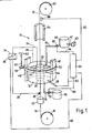
- apparatus 10 includes a container 12 for holding a slurry 14 in which very fine particles of superconductor material are suspended.
- the superconductor material is from the group identified as RE Ba2Cu3O 7-x (where x is in the range of 0-1).
- slurry 14 comprises a nonaqueous solution.
- the nonaqueous solution should be nonreactive with the superconductor material and preferably comprise a solvent, such as isopropanol, with a relatively small amount (e.g.
- an additive such as ethanolamine
- ethanolamine a product commercially known as Emphos P21
- the slurry 14 must remain effectively moisture-free and both the solvent (isopropanol) and the additive (ethanolamine) in slurry 14 should evaporate or decompose at relatively low temperatures (i.e. somewhere below 300°C) in order to prevent subsequent reactions of these ingredients with the superconductor material.
- a metallic substrate 16 on which the superconductor particles suspended in slurry 14 are to be coated, is fed into or suspended in the slurry 14.
- This substrate 16 may be formed as either a ribbon or a wire fiber.
- the actual form or configuration of substrate 16 is not, however, a limiting consideration. In fact, any configuration will work so long as it can function effectively as an electrode.
- substrate 16 should not interdiffuse with the superconductor particles.
- substrate 16 can be made of an inert metal such as gold or silver.
- substrate 16 will preferably lend itself to the establishment of an oxide barrier on its surface which will minimize the interdiffusion of substrate 16 with the superconductor particles.
- substrate 16 should either be made of an oxide forming material, such as the wire commercially available as Hoskins 875, or have a thin oxide layer deposited on it, such as Barium Zirconate (BaZrO3).
- substrate 16 is made of an oxide forming material such as used for the wire of Hoskins 875.
- an oxide forming material such as used for the wire of Hoskins 875.
- substrate 16 can be electrophoretically coated with superconductor particles at relatively low temperatures before being subjected to the much higher temperatures which are necessary to form an oxide barrier on the surface of substrate 16 (e.g. 850°C).
- oxide barrier on the surface of substrate 16 (e.g. 850°C).
- Suitable oxide forming materials for substrate 16 are materials, such as alumel or the commercially available material discussed above and known as Hoskins 875.
- Such materials will create an effective oxide barrier between substrate 16 and the superconductor coating during subsequent procedures wherein the superconductor particles are sintered into a ceramic. Examples of such procedures are disclosed in a co-pending application for an invention entitled "Substrate for Ceramic Superconductor" which is assigned to the same assignee as the present invention.
- the barrier should not electrically insulate the substrate 16 to the point where an electrophoresis process is made ineffectual.
- a suitable material in this case would be Nicrosil coated with Barium Zirconate.
- substrate 16 is fed from a supply spool 18 and through slurry 14 in container 12 to a take-up spool 20. More specifically, after leaving supply spool 18, substrate 16 is passed through a precleaner 22 (e.g. a furnace or a solvent in an ultrasonic bath) where it is cleaned of dust and other debris which may have settled onto the substrate 16 during handling. As also shown in Figure 1, substrate 16 is electrically biased. For this purpose, a voltage source 24 is placed in electrical contact with substrate 16 through line conductor 26 by any means known in the art, such as brush 28. Further, it will be appreciated that voltage source 24 could be a device, well known in the pertinent art, which provides a constant current. Also, though not shown, it will be appreciated that substrate 16 can be electrically biased by any direct electrical connection between voltage source 24 and substrate 16. Regardless, after leaving precleaner 22, substrate 16 is then passed into container 12 via inlet 30.
- precleaner 22 e.g. a furnace or a solvent in an ultrasonic bath
- voltage source 24 is also electrically connected with an open-ended metallic foil cylindrical tube 32.
- tube 32 is submersed in slurry 14 and is electrically connected to voltage source 24 via line 34.
- slurry 14 in container 12 is influenced by the electric field established between an electrode (i.e. tube 32) and a counterelectrode (i.e. substrate 16).
- tube 32 can be eliminated and voltage source 24 directly connected to container 12 via line 36. This connection will then establish container 12 as the electrode of the apparatus 10. This, of course, requires that container 12 be made of an electrically conducting material.
- tube 32 is established as the anode and substrate 16 is established as the cathode.
- the charges on electrodes and counterelectrodes can be alternated and, further, that the manipulation of rheostat 38 on voltage source 24 will vary the level of the voltage potential between anode and cathode.
- voltages typically, voltages of from 1-100 volts and corresponding currents in the range of 10 microamps to 1 milliamp are effective for the purposes of the present invention.
- rheostat 38 (or a digital voltage source) can be used to establish the voltage levels of the electric field influencing slurry 14 and thereby effectively establish the thickness of the coating of superconductor particles on substrate 16.
- the electric field influencing slurry 14 is set to cause the superconductor particles, which are colloidally suspended in the slurry 14, to migrate toward substrate 16 and become attached thereto. This process will, of course, require that the superconductor particles carry a charge. To accomplish this, the superconductor particles are mixed with the nonaqueous solution and then agitated. Effective agitation can be done either ultrasonically or by milling the particles in a manner well known in the pertinent art. Although slurry 14 should not be vibrated once it is placed into container 12, an effective way in which slurry 14 may be vibrated is by ultrasonic energy which is generated by an ultrasonic source 40 that is operatively connected to tank 66.
- a transducer probe 42 extends from source 40 into slurry 14 in container 66 to agitate the superconductor particles therein to charge the particles in a manner well known in the art. It will be recalled that the additive ethanolamine in slurry 14 is also intended to enhance the charge on superconductor particles.
- slurry 14 in addition to being influenced by an electric field, is also influenced by a magnetic field.
- a magnet device 44 is provided.
- the magnet device 44 is shown as a pair of permanent magnets, respectively designated 46 and 48, which are connected together by a flux return element 50 and positioned externally to container 12 on substantially opposite sides thereof.
- slurry 14 is effectively influenced by a magnetic field whose strength and uniformity is dependent, in part, on the size of magnets 46, 48 and whose flux lines within slurry 14 are substantially aligned in a direction which is perpendicular to the longitudinal axis of substrate 16.
- a magnet device 52 comprising a solenoid winding 54, as shown in Figure 2, may be used.
- the magnetic field strength of this magnet device 52 will depend, in part, on the current in winding 54 and the direction of the flux lines generated by magnet device 52 will be in a direction which is substantially parallel to the longitudinal axis of substrate 16. From the discussion below, it will be seen that it is important for the direction of flux to be compatible with the magnetic properties of the 1-2-3 particles.
- FIG. 3 An exemplary configuration of a superconductor particle is shown as plate 56 in Figure 3.
- the critical current densities (J c ) of the plate 56 vary according to the axis along which current flows. Specifically, J c in both the "a" and “b” directions shown in Figure 3 are on the order of thirty (30) times greater than J c in the "c" direction. Accordingly, in order to optimize current flow in the resultant product, it is desirable if plates 56 are properly oriented on substrate 16 with their respective "c" directions substantially perpendicular to the longitudinal axis of substrate 16. The magnetic field generated by magnet device 44 or magnet device 52 is intended to accomplish this.
- RE Ba2Cu3O 7-x i.e. 1-2-3
- RE Ba2Cu3O 7-x i.e. 1-2-3
- the orientation of a plate 56 in a magnetic field of flux H is, at least to some extent, predictable.
- some rare earth 1-2-3 materials orient in a flux field H with their "c" direction parallel to the lines as shown in Figure 4A, while others orient themselves with their "c” direction perpendicular to the lines of flux as shown in Figure 4B.
- the rare earth elements which orient with the "c" direction parallel to H include Yttrium (Y), Neodymium (Nd), Samarium (Sm), Dysprosium (Dy) and Holmium (Ho).
- the rare earth elements which orient with the "c" direction perpendicular to H include Europium (Eu), Erbium (Er), Thulium (Tm) and Ytterbium (Yb).
- Eu Europium
- Er Er
- Tm Thulium
- Yb Ytterbium
- substrate 16 can be rotated during the coating process or the magnet device itself can be rotated. Though not shown, it will be appreciated that substrate 16 may be rotated by any means well known in the art. Further, substrate 16 need not necessarily pass through slurry 14. Instead, substrate 16 may be suspended in slurry 14 and rotated therein. In any case, to avoid an anisotropic coating, it is necessary to charge substrate 16 and rotate it in slurry 14 to obtain a uniform coating of the magnetically influenced superconductor particles.
- magnet device 44 can be slidingly mounted on container 12 for rotation with respect thereto.
- a roller 58 can be operatively engaged with magnet device 44, by any means well known in the art, so that rotation of roller 58 about an axis 60 in the direction of arrow 62 will cause magnet device 44 to rotate about container 12 while maintaining flux lines in slurry 14 substantially perpendicular to the longitudinal axis of substrate 16.
- an anisotropic coating of substrate 16 can be obviated.
- magnets 44, 46 partially extend above container 12. Accordingly, the superconductor particles from slurry 14 which attach to substrate 12 continue to be influenced by a magnetic field even after passing through slurry 14. This configuration is established in order to keep the superconductor particles properly aligned on substrate 16 during the evaporation of nonaqueous solution, and prior to sintering.
- An oven 64 is provided to sinter the superconductor particles which are attached to substrate 16 into a ceramic.
- the ceramic superconductor coated substrate 16 can then be wound onto take-up spool 20 and used thereafter as desired.
- a slurry 14 having slightly higher superconductor particle concentration levels than desired for use in container 12 is provided and held in supply tank 66.
- the operation of supply valve 68 will open pipe 70 and allow high concentration slurry 14 from supply tank 66 to be introduced into the slurry 14 in container 12.
- operation of drain valve 72 allows low concentration slurry 14 in container 12 to be withdrawn from container 12 through pipe 74 into holding tank 76.
- the maintenance of superconductor concentration levels in container 12 can be accomplished with a closed loop feedback control system.
- a probe 78 is inserted into slurry 14 and is used to test samples of slurry 14 for viscosity and generate a reading of the superconductor concentration levels in the samples.
- Probe 78 may be of any type well known in the art for testing fluid viscosity.
- This reading is transmitted via line 80 to a microprocessor 82 which, depending on the concentration level indicated by the reading from probe 78, will transmit signals via lines 84, 86 to supply valve 68 and drain valve 72, respectively, to charge the flow through the valves 68, 72 to effectively maintain the concentration of superconductor particles in slurry 14 in container 12 at the desired level.
- the thickness of the superconductor ceramic coating of substrate 16 can be automatically controlled using microprocessor 82 in a standard closed loop feedback control system similar to the one used for controlling slurry 14 superconductor concentration.
- any device 88 that is well known in the art for measuring the diameter of a wire, can be positioned relative to substrate 16 to determine the diameter of the ceramic coated substrate 16. This measurement can then be sent as an electrical signal via line 90 to microprocessor 82.
- Microprocessor 82 then compares the signal from device 88 with a predetermined reference level to establish an error signal. This error signal is then sent via line 92 to rheostat 38 and, depending on the sign and magnitude of this error signal, rheostat 38 is moved to vary the voltage level of source 24 to control the thickness of superconductor ceramic coating on substrate 16.
- apparatus 10 be enclosed in a dry room where the ambient humidity and carbon dioxide concentrations can be controlled and maintained at very low levels.
Landscapes
- Engineering & Computer Science (AREA)
- Manufacturing & Machinery (AREA)
- Superconductors And Manufacturing Methods Therefor (AREA)
- Superconductor Devices And Manufacturing Methods Thereof (AREA)
- Inorganic Compounds Of Heavy Metals (AREA)
Applications Claiming Priority (2)
| Application Number | Priority Date | Filing Date | Title |
|---|---|---|---|
| US07/289,968 US5108982A (en) | 1988-12-22 | 1988-12-22 | Apparatus and method for manufacturing a ceramic superconductor coated metal fiber |
| US289968 | 2002-11-07 |
Publications (2)
| Publication Number | Publication Date |
|---|---|
| EP0375276A2 true EP0375276A2 (de) | 1990-06-27 |
| EP0375276A3 EP0375276A3 (de) | 1992-01-02 |
Family
ID=23113966
Family Applications (1)
| Application Number | Title | Priority Date | Filing Date |
|---|---|---|---|
| EP19890313072 Withdrawn EP0375276A3 (de) | 1988-12-22 | 1989-12-14 | Vorrichtung zur Herstellung von langförmigen Supraleitern |
Country Status (4)
| Country | Link |
|---|---|
| US (1) | US5108982A (de) |
| EP (1) | EP0375276A3 (de) |
| JP (1) | JP2907471B2 (de) |
| CA (1) | CA2004897C (de) |
Cited By (6)
| Publication number | Priority date | Publication date | Assignee | Title |
|---|---|---|---|---|
| EP0476878A3 (en) * | 1990-09-21 | 1992-07-22 | General Atomics | Process and apparatus for fabrication of silver coated high temperature ceramic superconductor fiber with metal substrate |
| EP0476879A3 (en) * | 1990-09-21 | 1992-08-05 | General Atomics | Apparatus and method for manufacturing an improved ceramic superconductor coated metal fiber |
| EP0476881A3 (en) * | 1990-09-21 | 1992-08-05 | General Atomics | Anhydrous electrophoretic silver coating technique |
| EP0512679A3 (en) * | 1991-05-02 | 1993-01-27 | General Electric Company | Method of making laser ablated oriented films on metal substrates and articles formed thereby |
| EP0507539A3 (en) * | 1991-04-01 | 1993-01-27 | General Electric Company | Method of making oriented dielectric films on metal substrates and articles formed thereby |
| GB2263075B (en) * | 1991-12-17 | 1995-11-08 | Secr Defence | Production of ceramic filamentary coatings |
Families Citing this family (15)
| Publication number | Priority date | Publication date | Assignee | Title |
|---|---|---|---|---|
| US5660541A (en) * | 1994-10-13 | 1997-08-26 | General Atomics | Method for heat treating long lengths of silver clad high temperature superconductor |
| US5872081A (en) * | 1995-04-07 | 1999-02-16 | General Atomics | Compositions for melt processing high temperature superconductor |
| JP3444893B2 (ja) | 1995-05-19 | 2003-09-08 | アメリカン スーパーコンダクター コーポレイション | マルチフィラメント状超伝導性複合材料および製法 |
| DE19535262A1 (de) * | 1995-09-22 | 1997-03-27 | Josef Dr Heyes | Verfahren zur elektrophoretischen Herstellung von supraleitenden Drähten |
| US5868897A (en) * | 1996-07-31 | 1999-02-09 | Toyo Technologies, Inc. | Device and method for processing a plasma to alter the surface of a substrate using neutrals |
| US5993678A (en) * | 1996-07-31 | 1999-11-30 | Toyo Technologies Inc. | Device and method for processing a plasma to alter the surface of a substrate |
| US5763017A (en) * | 1996-10-28 | 1998-06-09 | Toyo Technologies Inc. | Method for producing micro-bubble-textured material |
| US6428635B1 (en) | 1997-10-01 | 2002-08-06 | American Superconductor Corporation | Substrates for superconductors |
| US6458223B1 (en) | 1997-10-01 | 2002-10-01 | American Superconductor Corporation | Alloy materials |
| US6475311B1 (en) | 1999-03-31 | 2002-11-05 | American Superconductor Corporation | Alloy materials |
| CA2308092C (en) | 2000-05-10 | 2008-10-21 | Partho Sarkar | Production of hollow ceramic membranes by electrophoretic deposition |
| US20040118686A1 (en) * | 2002-10-02 | 2004-06-24 | Jan Ma | Piezoelectric tubes |
| US20050256011A1 (en) * | 2004-01-23 | 2005-11-17 | Metal Oxide Technologies, Inc. | System and method for quality testing of superconducting tape |
| US20070132153A1 (en) * | 2005-12-13 | 2007-06-14 | Aiyer Hemantkumar N | Ceramic arc tubes with reduced surface scatter and related methods |
| CN111546676B (zh) * | 2020-05-27 | 2021-09-17 | 台州巨壹塑业有限公司 | 一种纤维加强的pvc软管的生产工艺 |
Family Cites Families (13)
| Publication number | Priority date | Publication date | Assignee | Title |
|---|---|---|---|---|
| US2478322A (en) * | 1946-09-18 | 1949-08-09 | Sprague Electric Co | Process for producing improved electrical conductors |
| DE1796176A1 (de) * | 1967-09-14 | 1972-03-23 | Sumitomo Electric Industries | Isolierter Draht und Verfahren zu dessen Herstellung |
| DE1921982C3 (de) * | 1969-04-30 | 1978-11-09 | The Sherwin-Williams Co., Cleveland, Ohio (V.St.A.) | Verfahren zum elektrophoretischen Beschichten der Oberfläche eines elektrischen Leiters mit einem polymeren Produkt |
| US3835005A (en) * | 1972-10-27 | 1974-09-10 | Canada Wire & Cable Co Ltd | Electrocoating process and apparatus |
| DE2613285C3 (de) * | 1976-03-29 | 1978-09-21 | Battelle-Institut E.V., 6000 Frankfurt | Verfahren und Vorrichtung zur Herstellung von supraleitfähigen! Material |
| US4126523A (en) * | 1976-10-21 | 1978-11-21 | Alumatec, Inc. | Method and means for electrolytic precleaning of substrates and the electrodeposition of aluminum on said substrates |
| JP2649674B2 (ja) * | 1987-05-26 | 1997-09-03 | 住友電気工業株式会社 | 複合セラミックス超電導体 |
| EP0293981A3 (de) * | 1987-06-04 | 1990-10-10 | Imi Titanium Limited | Verfahren zur Herstellung eines anorganischen Halbleiterverbundwerkstoffes und so erzeugte Produkte |
| GB8717360D0 (en) * | 1987-07-22 | 1987-08-26 | Chloride Silent Power Ltd | Preparing superconducting ceramic materials |
| US4942151A (en) * | 1987-09-28 | 1990-07-17 | Arch Development Corporation | Magnetic preferential orientation of metal oxide superconducting materials |
| US4952557A (en) * | 1987-11-09 | 1990-08-28 | Ametek, Inc. | Formation of superconducting articles by electrodeposition |
| US4870051A (en) * | 1988-04-29 | 1989-09-26 | Allied-Signal Inc. | Method of forming superconducting ceramics by electrodeposition |
| US4939121A (en) * | 1988-10-20 | 1990-07-03 | General Dynamics Corporation, Electronics Division | Method and apparatus for inducing grain orientation by magnetic and electric field ordering during bulk superconductor synthesis |
-
1988
- 1988-12-22 US US07/289,968 patent/US5108982A/en not_active Expired - Fee Related
-
1989
- 1989-12-07 CA CA002004897A patent/CA2004897C/en not_active Expired - Fee Related
- 1989-12-14 EP EP19890313072 patent/EP0375276A3/de not_active Withdrawn
- 1989-12-21 JP JP1332529A patent/JP2907471B2/ja not_active Expired - Lifetime
Cited By (6)
| Publication number | Priority date | Publication date | Assignee | Title |
|---|---|---|---|---|
| EP0476878A3 (en) * | 1990-09-21 | 1992-07-22 | General Atomics | Process and apparatus for fabrication of silver coated high temperature ceramic superconductor fiber with metal substrate |
| EP0476879A3 (en) * | 1990-09-21 | 1992-08-05 | General Atomics | Apparatus and method for manufacturing an improved ceramic superconductor coated metal fiber |
| EP0476881A3 (en) * | 1990-09-21 | 1992-08-05 | General Atomics | Anhydrous electrophoretic silver coating technique |
| EP0507539A3 (en) * | 1991-04-01 | 1993-01-27 | General Electric Company | Method of making oriented dielectric films on metal substrates and articles formed thereby |
| EP0512679A3 (en) * | 1991-05-02 | 1993-01-27 | General Electric Company | Method of making laser ablated oriented films on metal substrates and articles formed thereby |
| GB2263075B (en) * | 1991-12-17 | 1995-11-08 | Secr Defence | Production of ceramic filamentary coatings |
Also Published As
| Publication number | Publication date |
|---|---|
| EP0375276A3 (de) | 1992-01-02 |
| CA2004897C (en) | 2000-02-08 |
| JPH02243796A (ja) | 1990-09-27 |
| CA2004897A1 (en) | 1990-06-22 |
| JP2907471B2 (ja) | 1999-06-21 |
| US5108982A (en) | 1992-04-28 |
Similar Documents
| Publication | Publication Date | Title |
|---|---|---|
| US5108982A (en) | Apparatus and method for manufacturing a ceramic superconductor coated metal fiber | |
| JP3322891B2 (ja) | 超伝導体ワイヤの製造方法及び装置 | |
| US4963524A (en) | Sputtering device for manufacturing superconducting oxide material and method therefor | |
| EP0476879A2 (de) | Apparat und Verfahren zur Herstellung einer verbesserten keramisch-supraleitend beschichteten Metall-Fiber | |
| US20040246650A1 (en) | Highly conductive macromolecular materials and improved methods for making same | |
| US5318951A (en) | Method for fabricating oxide superconducting coatings | |
| EP0476881A2 (de) | Anhydritische elektrophoretische Silberbeschichtungstechnik | |
| US3752751A (en) | Process for forming an electrically conductive coating on a nonmetallic filament | |
| US5244875A (en) | Electroplating of superconductor elements | |
| Mogi et al. | The effect of very high magnetic fields on cyclic voltammetry. | |
| US3645787A (en) | Method of forming multiple layer structures including magnetic domains | |
| JP2000038696A (ja) | 軸受の製造方法 | |
| Chou et al. | Diffusivity of oxygen in liquid Sn and Ba0. 35Cu0. 65 alloys | |
| Takeo | Copper electrodeposition in a magnetic field | |
| EP1403938A1 (de) | Herstellungsverfahren für ein fluxmeter des quanteninterferenztyps | |
| JP2583576B2 (ja) | 酸化物超電導材の製造方法 | |
| WO1997015067A2 (en) | A method of biaxially aligning crystalline material | |
| JPH0337104A (ja) | 超電導体薄膜の製造方法および装置 | |
| JPH03120395A (ja) | 酸化ビスマスのコーティング法 | |
| EP0400057A4 (en) | Preparation of superconducting oxides by electrochemical oxidation: anodic superconductors | |
| Ceresara et al. | Y-Ba-Cu-O thick films prepared by electrophoresis on silver substrates | |
| JPH01108122A (ja) | 超電導薄膜の製造方法 | |
| JPH0570104A (ja) | 酸化物超電導膜の製造方法 | |
| KR20050045646A (ko) | 전기 영동 전착 장치 | |
| WO2003012888A1 (fr) | Procede de formation de films supraconducteurs |
Legal Events
| Date | Code | Title | Description |
|---|---|---|---|
| PUAI | Public reference made under article 153(3) epc to a published international application that has entered the european phase |
Free format text: ORIGINAL CODE: 0009012 |
|
| AK | Designated contracting states |
Kind code of ref document: A2 Designated state(s): AT BE DE FR GB IT NL SE |
|
| PUAL | Search report despatched |
Free format text: ORIGINAL CODE: 0009013 |
|
| AK | Designated contracting states |
Kind code of ref document: A3 Designated state(s): AT BE DE FR GB IT NL SE |
|
| STAA | Information on the status of an ep patent application or granted ep patent |
Free format text: STATUS: THE APPLICATION IS DEEMED TO BE WITHDRAWN |
|
| 18D | Application deemed to be withdrawn |
Effective date: 19920703 |