EP0376169A2 - Automatisches Getriebe für Quereinbau - Google Patents
Automatisches Getriebe für Quereinbau Download PDFInfo
- Publication number
- EP0376169A2 EP0376169A2 EP89123692A EP89123692A EP0376169A2 EP 0376169 A2 EP0376169 A2 EP 0376169A2 EP 89123692 A EP89123692 A EP 89123692A EP 89123692 A EP89123692 A EP 89123692A EP 0376169 A2 EP0376169 A2 EP 0376169A2
- Authority
- EP
- European Patent Office
- Prior art keywords
- transaxle
- center axis
- control valve
- differential
- valve assembly
- Prior art date
- Legal status (The legal status is an assumption and is not a legal conclusion. Google has not performed a legal analysis and makes no representation as to the accuracy of the status listed.)
- Granted
Links
Images


Classifications
-
- B—PERFORMING OPERATIONS; TRANSPORTING
- B60—VEHICLES IN GENERAL
- B60K—ARRANGEMENT OR MOUNTING OF PROPULSION UNITS OR OF TRANSMISSIONS IN VEHICLES; ARRANGEMENT OR MOUNTING OF PLURAL DIVERSE PRIME-MOVERS IN VEHICLES; AUXILIARY DRIVES FOR VEHICLES; INSTRUMENTATION OR DASHBOARDS FOR VEHICLES; ARRANGEMENTS IN CONNECTION WITH COOLING, AIR INTAKE, GAS EXHAUST OR FUEL SUPPLY OF PROPULSION UNITS IN VEHICLES
- B60K17/00—Arrangement or mounting of transmissions in vehicles
- B60K17/04—Arrangement or mounting of transmissions in vehicles characterised by arrangement, location or kind of gearing
- B60K17/06—Arrangement or mounting of transmissions in vehicles characterised by arrangement, location or kind of gearing of change-speed gearing
- B60K17/08—Arrangement or mounting of transmissions in vehicles characterised by arrangement, location or kind of gearing of change-speed gearing of mechanical type
-
- F—MECHANICAL ENGINEERING; LIGHTING; HEATING; WEAPONS; BLASTING
- F16—ENGINEERING ELEMENTS AND UNITS; GENERAL MEASURES FOR PRODUCING AND MAINTAINING EFFECTIVE FUNCTIONING OF MACHINES OR INSTALLATIONS; THERMAL INSULATION IN GENERAL
- F16H—GEARING
- F16H61/00—Control functions within control units of change-speed- or reversing-gearings for conveying rotary motion ; Control of exclusively fluid gearing, friction gearing, gearings with endless flexible members or other particular types of gearing
- F16H61/0003—Arrangement or mounting of elements of the control apparatus, e.g. valve assemblies or snapfittings of valves; Arrangements of the control unit on or in the transmission gearbox
- F16H61/0009—Hydraulic control units for transmission control, e.g. assembly of valve plates or valve units
-
- Y—GENERAL TAGGING OF NEW TECHNOLOGICAL DEVELOPMENTS; GENERAL TAGGING OF CROSS-SECTIONAL TECHNOLOGIES SPANNING OVER SEVERAL SECTIONS OF THE IPC; TECHNICAL SUBJECTS COVERED BY FORMER USPC CROSS-REFERENCE ART COLLECTIONS [XRACs] AND DIGESTS
- Y10—TECHNICAL SUBJECTS COVERED BY FORMER USPC
- Y10T—TECHNICAL SUBJECTS COVERED BY FORMER US CLASSIFICATION
- Y10T74/00—Machine element or mechanism
- Y10T74/21—Elements
- Y10T74/2186—Gear casings
Definitions
- the present invention relates to an automatic transaxle for a front engine-front drive vehicle.
- a control valve assembly is arranged so as to have a portion right under an idler or reduction gear, i.e., the control valve is arranged so as to extend over the opposite sides of a transaxle case divided by an idler gear center axis.
- a novel automatic transaxle which comprises a main power train having a center axis, a differential having a center axis, an idler gear interposed betrween the main power train and the differential for transmission of power therebetween and having a center axis prallel to the center axes of the main power train and the differential, a transaxle case having installed therein the main power train, the differential and the idler gear, the transaxle case having opposite sides divided by the center axis of the idler gear, the differenital being disposed on one of the opposite sides of the transaxle case, and a control valve assembly disposed on the other of the opposite sides of the transaxle case.
- the automatic transaxle further comprises an oil storing chamber which is disposed next to the control valve assembly and free from occupation by same.
- the oil storing chamber extends from the aforementioned one side to the aforementioned other side of the transaxle case.
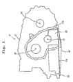
- an automatic transaxle 10 includes a transaxle case 12 for receiving therein a main power train 14, a differential 16, etc.
- a center axis of the main power train 14 is indicated by 18.
- a center axis of the differential 16 is indicated by 20.
- a center axis of a reduction gear or idler gear 21 is indicated by 22.
- An idler shaft or reduction shaft for installing thereon the idler or reduction gear 21 is indicated by 24.
- the center axes 18, 20 and 22 are parallel to each other.
- the center axis 22 of the differential 16 is arranged so as to be lower than a plane 25 interconnecting the center axes 18 and 20 of the main power train 14 and the differential 16 as best seen from Fig. 3.
- the automatic transaxle 10 further includes a control valve assembly 26 consisting of an upper body 26a, middle body 26b and lower body 26c.
- the transaxle case 12 is formed with an attaching surface 12c to which the control valve assembly 26 is attached and fastened.
- the control valve assembly 26 is arranged forward of the reduction shaft 24 with respect to an associated vehicle body and in such a manner that the upper body 26a projecting into a place higher than the lower end of the reduction shaft 24.
- the control valve assembly 26 is arranged on one of opposite sides of the transaxle case 12 divided by the center axis 22 of the idler gear 22 or shaft 24, while on the contrary the differential 14 is disposed on the other of the opposite sides of the transaxle case 12.
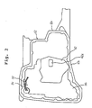
- the transaxle case 12 has at the lower end portion thereof an oil storing space or chamber 28 which is disposed next to the control valve assembly 26 and is not occupied by same. More specifically, the oil storing chamber 28 is arranged so as to extend nearly horizontally from one to the other of the opposite sides of the transaxle case 12 divided by the center axis 22 of the idler gear 21 or shaft 24, i.e.,, the oil storing chamber 28 extends from the control valve assembly 26 receiving side to the differential 16 receiving side of the transaxle case 12 divided by the center axis 22 of the idler gear 21 or shaft 24.
- the end of the oil storing chamber 28 on the differential 16 receiving side is defined by a wall 12a of the casing 12.
- An oil pan 30 extends correspondingly to the oil storing chamber 28, i.e., the oil pan 30 is constructed and arranged so as to extend from one to the other of the opposite sides of the transaxle case 12 divided by the center axis 22 of the idler gear 21 or shaft 24.
- the oil pan 30 is attached to a lower end flange 12b of the transaxle case 12 to define the lower end of the storing chamber 28.
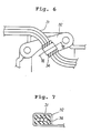
- a harness is indicated by 31 and attached to the control valve assembly 26 by means of a clamp 32.
- the clamp 32 is partially cut and bent so as to encircle the harness 31 by way of a rubber bushing 34 for thereby holding the harness 31 in place relative to the control valve assembly 26.
- the present invention makes it possible for the control valve assembly to be arranged generally higher than before relative to the lower end of the transaxle case or the control valve assembly attaching surface of the transaxle case. This makes it possible for the control valve to be thicker than before.
- Figs. 8 shows an example in which an oil storing cahmber 28′ is provided which is mostly occupied by the control valve assembly 26.
- the oil storing chamber 28′ is not extended from one to the other of the opposite sides of the transaxle case 12 divided by the center axis 22 of the idler gear 21 or shaft 24.
- 36 indicates an oil level when the vehicle is on a planar road surface
- 38 indicates an oil level when the vehicle is on an uphill road or accelerated
- 40 indicates an oil level when the vehicle is on a downhill road or decelerated.
- the oil level 36 is inevitable in order to prevent an oil intake port 42a of an oil strainer 42 from being exposed to the open air to inhale air.
- the oil levels 36-40 are undesirable since they interfere with the main power train 14 to cause an excessively high temperature of oil. If the oil level 36 is lowered so as not to interfere with the main power train 14, the inlet port 42a of the strainer 42 may possibly be exposed to the open air to inhale air when the vehicle is on an uphill road or accelerated. This is undesirable.
- the present invention makes it possible to attain the oil storing chamber 28 which is not occupied by the control valve assembly 26 and which extends from one to the other of the opposite sides of the center axis 22 of the idler gear 21 or shaft 24 since the control valve assembly 26 is arranged only on one side with respect to the idler shaft 24.
- the control valve assembly 26 is arranged only on one side with respect to the idler shaft 24.
Landscapes
- Engineering & Computer Science (AREA)
- General Engineering & Computer Science (AREA)
- Mechanical Engineering (AREA)
- Chemical & Material Sciences (AREA)
- Combustion & Propulsion (AREA)
- Transportation (AREA)
- General Details Of Gearings (AREA)
Applications Claiming Priority (4)
| Application Number | Priority Date | Filing Date | Title |
|---|---|---|---|
| JP331315/88 | 1988-12-29 | ||
| JP33131588A JPH02179543A (ja) | 1988-12-29 | 1988-12-29 | オートマチックトランスアクスル |
| JP331316/88 | 1988-12-29 | ||
| JP33131688A JPH02179544A (ja) | 1988-12-29 | 1988-12-29 | オートマチックトランスアクスル |
Publications (3)
| Publication Number | Publication Date |
|---|---|
| EP0376169A2 true EP0376169A2 (de) | 1990-07-04 |
| EP0376169A3 EP0376169A3 (de) | 1991-04-10 |
| EP0376169B1 EP0376169B1 (de) | 1994-04-20 |
Family
ID=26573815
Family Applications (1)
| Application Number | Title | Priority Date | Filing Date |
|---|---|---|---|
| EP89123692A Expired - Lifetime EP0376169B1 (de) | 1988-12-29 | 1989-12-21 | Automatisches Getriebe für Quereinbau |
Country Status (3)
| Country | Link |
|---|---|
| US (1) | US5078662A (de) |
| EP (1) | EP0376169B1 (de) |
| DE (1) | DE68914814T2 (de) |
Cited By (1)
| Publication number | Priority date | Publication date | Assignee | Title |
|---|---|---|---|---|
| US6526848B2 (en) * | 2000-09-08 | 2003-03-04 | Honda Giken Kogyo Kabushiki Kaisha | Vehicle transmission |
Families Citing this family (5)
| Publication number | Priority date | Publication date | Assignee | Title |
|---|---|---|---|---|
| KR960005976B1 (ko) * | 1991-07-31 | 1996-05-06 | 마쯔다 가부시기가이샤 | 자동차의 파우어트레인의 구조 |
| US5287769A (en) * | 1992-07-02 | 1994-02-22 | Tecumseh Products Company | Offset shaft arrangement for in-line shift transaxle housing |
| US5259271A (en) * | 1992-12-18 | 1993-11-09 | Chrysler Corporation | North-south automatic transaxle |
| US6332962B1 (en) * | 1997-06-13 | 2001-12-25 | Micrion Corporation | Thin-film magnetic recording head manufacture using selective imaging |
| JP3461329B2 (ja) * | 2000-07-05 | 2003-10-27 | 本田技研工業株式会社 | 無段変速機の油圧制御装置 |
Family Cites Families (6)
| Publication number | Priority date | Publication date | Assignee | Title |
|---|---|---|---|---|
| JPS5540368A (en) * | 1978-09-18 | 1980-03-21 | Nissan Motor Co Ltd | Output gear bearing device of automatic transmission gear for front-drive car |
| US4528870A (en) * | 1982-05-04 | 1985-07-16 | Van Doorne's Transmissie B.V. | Transmission for vehicles, in particular for automobiles with front wheel drive |
| JPS58196466A (ja) * | 1982-05-13 | 1983-11-15 | Omron Tateisi Electronics Co | ケ−ブル等の特性測定方法 |
| JPS58196466U (ja) * | 1982-06-25 | 1983-12-27 | トヨタ自動車株式会社 | 自動変速機のトランスアクスルケ−ス |
| JPH0536114Y2 (de) * | 1986-07-23 | 1993-09-13 | ||
| JPH0545891Y2 (de) * | 1987-03-31 | 1993-11-29 |
-
1989
- 1989-12-05 US US07/446,531 patent/US5078662A/en not_active Expired - Lifetime
- 1989-12-21 EP EP89123692A patent/EP0376169B1/de not_active Expired - Lifetime
- 1989-12-21 DE DE68914814T patent/DE68914814T2/de not_active Expired - Lifetime
Cited By (1)
| Publication number | Priority date | Publication date | Assignee | Title |
|---|---|---|---|---|
| US6526848B2 (en) * | 2000-09-08 | 2003-03-04 | Honda Giken Kogyo Kabushiki Kaisha | Vehicle transmission |
Also Published As
| Publication number | Publication date |
|---|---|
| EP0376169A3 (de) | 1991-04-10 |
| EP0376169B1 (de) | 1994-04-20 |
| US5078662A (en) | 1992-01-07 |
| DE68914814T2 (de) | 1994-08-04 |
| DE68914814D1 (de) | 1994-05-26 |
Similar Documents
| Publication | Publication Date | Title |
|---|---|---|
| US4995971A (en) | Dual purpose automatic transmission oil pan | |
| US4911035A (en) | Air breather device of automatic transmission | |
| US4938184A (en) | Engine oil return system | |
| US4546750A (en) | Secondary reservoir for a fuel tank | |
| US4309155A (en) | Vehicle fuel tank having vented internal fuel pump | |
| GB2191538A (en) | Dry sump crankcase | |
| EP0376169A2 (de) | Automatisches Getriebe für Quereinbau | |
| US20050107202A1 (en) | Automatic transmission oil leak prevention device | |
| US4212600A (en) | Vehicle fuel tank having vented internal fuel pump | |
| US6796283B1 (en) | Oiling system for an internal combustion engine | |
| US3805920A (en) | Oil pan for an engine | |
| JPS6040804Y2 (ja) | エンジンの潤滑装置 | |
| EP1371821B1 (de) | Ölwanne | |
| GB2227215A (en) | Motor vehicle front engine air intake arrangement | |
| US7299820B2 (en) | Hydraulic fluid reservoir | |
| EP0832777A1 (de) | Aufbau eines einfüllrohres | |
| JPS5811965Y2 (ja) | 車輌用油圧作動式変速機におけるオイル供給装置 | |
| EP0124771A1 (de) | Automatisches Getriebe | |
| EP0068361A1 (de) | Halteanordnung für einen Frontbremsschlauch an Kraftfahrzeugen | |
| US6205886B1 (en) | Control valve devices for automatic transmissions | |
| CN217783591U (zh) | 一种油底盘及其发动机、飞行器 | |
| JPH0320161A (ja) | 自動変速機のコントロールバルブユニット | |
| US12173783B2 (en) | Configurations of control valve unit and strainer in power transmitting device | |
| JPS6062617A (ja) | オイルパン内の潤滑油の流動抑制装置 | |
| JPS5954718A (ja) | 前輪駆動トラクタ用エンジンのオイルパン |
Legal Events
| Date | Code | Title | Description |
|---|---|---|---|
| PUAI | Public reference made under article 153(3) epc to a published international application that has entered the european phase |
Free format text: ORIGINAL CODE: 0009012 |
|
| 17P | Request for examination filed |
Effective date: 19891221 |
|
| AK | Designated contracting states |
Kind code of ref document: A2 Designated state(s): DE FR GB |
|
| PUAL | Search report despatched |
Free format text: ORIGINAL CODE: 0009013 |
|
| AK | Designated contracting states |
Kind code of ref document: A3 Designated state(s): DE FR GB |
|
| 17Q | First examination report despatched |
Effective date: 19920615 |
|
| RBV | Designated contracting states (corrected) |
Designated state(s): DE GB |
|
| GRAA | (expected) grant |
Free format text: ORIGINAL CODE: 0009210 |
|
| AK | Designated contracting states |
Kind code of ref document: B1 Designated state(s): DE GB |
|
| REF | Corresponds to: |
Ref document number: 68914814 Country of ref document: DE Date of ref document: 19940526 |
|
| PLBE | No opposition filed within time limit |
Free format text: ORIGINAL CODE: 0009261 |
|
| STAA | Information on the status of an ep patent application or granted ep patent |
Free format text: STATUS: NO OPPOSITION FILED WITHIN TIME LIMIT |
|
| 26N | No opposition filed | ||
| REG | Reference to a national code |
Ref country code: GB Ref legal event code: IF02 |
|
| PGFP | Annual fee paid to national office [announced via postgrant information from national office to epo] |
Ref country code: DE Payment date: 20081219 Year of fee payment: 20 |
|
| PGFP | Annual fee paid to national office [announced via postgrant information from national office to epo] |
Ref country code: GB Payment date: 20081217 Year of fee payment: 20 |
|
| REG | Reference to a national code |
Ref country code: GB Ref legal event code: PE20 Expiry date: 20091220 |
|
| PG25 | Lapsed in a contracting state [announced via postgrant information from national office to epo] |
Ref country code: GB Free format text: LAPSE BECAUSE OF EXPIRATION OF PROTECTION Effective date: 20091220 |