EP0376283A2 - Automatisches Wechselgetriebe mit einer zusätzlichen Getriebestufe - Google Patents
Automatisches Wechselgetriebe mit einer zusätzlichen Getriebestufe Download PDFInfo
- Publication number
- EP0376283A2 EP0376283A2 EP89124027A EP89124027A EP0376283A2 EP 0376283 A2 EP0376283 A2 EP 0376283A2 EP 89124027 A EP89124027 A EP 89124027A EP 89124027 A EP89124027 A EP 89124027A EP 0376283 A2 EP0376283 A2 EP 0376283A2
- Authority
- EP
- European Patent Office
- Prior art keywords
- subsidiary
- primary
- transmission
- establishing
- transmission unit
- Prior art date
- Legal status (The legal status is an assumption and is not a legal conclusion. Google has not performed a legal analysis and makes no representation as to the accuracy of the status listed.)
- Granted
Links
Images


Classifications
-
- F—MECHANICAL ENGINEERING; LIGHTING; HEATING; WEAPONS; BLASTING
- F16—ENGINEERING ELEMENTS AND UNITS; GENERAL MEASURES FOR PRODUCING AND MAINTAINING EFFECTIVE FUNCTIONING OF MACHINES OR INSTALLATIONS; THERMAL INSULATION IN GENERAL
- F16H—GEARING
- F16H61/00—Control functions within control units of change-speed- or reversing-gearings for conveying rotary motion ; Control of exclusively fluid gearing, friction gearing, gearings with endless flexible members or other particular types of gearing
- F16H61/04—Smoothing ratio shift
- F16H61/06—Smoothing ratio shift by controlling rate of change of fluid pressure
- F16H61/061—Smoothing ratio shift by controlling rate of change of fluid pressure using electric control means
-
- F—MECHANICAL ENGINEERING; LIGHTING; HEATING; WEAPONS; BLASTING
- F16—ENGINEERING ELEMENTS AND UNITS; GENERAL MEASURES FOR PRODUCING AND MAINTAINING EFFECTIVE FUNCTIONING OF MACHINES OR INSTALLATIONS; THERMAL INSULATION IN GENERAL
- F16H—GEARING
- F16H61/00—Control functions within control units of change-speed- or reversing-gearings for conveying rotary motion ; Control of exclusively fluid gearing, friction gearing, gearings with endless flexible members or other particular types of gearing
- F16H61/70—Control functions within control units of change-speed- or reversing-gearings for conveying rotary motion ; Control of exclusively fluid gearing, friction gearing, gearings with endless flexible members or other particular types of gearing specially adapted for change-speed gearing in group arrangement, i.e. with separate change-speed gear trains arranged in series, e.g. range or overdrive-type gearing arrangements
- F16H61/705—Control functions within control units of change-speed- or reversing-gearings for conveying rotary motion ; Control of exclusively fluid gearing, friction gearing, gearings with endless flexible members or other particular types of gearing specially adapted for change-speed gearing in group arrangement, i.e. with separate change-speed gear trains arranged in series, e.g. range or overdrive-type gearing arrangements using hydraulic and mechanical control means
-
- F—MECHANICAL ENGINEERING; LIGHTING; HEATING; WEAPONS; BLASTING
- F16—ENGINEERING ELEMENTS AND UNITS; GENERAL MEASURES FOR PRODUCING AND MAINTAINING EFFECTIVE FUNCTIONING OF MACHINES OR INSTALLATIONS; THERMAL INSULATION IN GENERAL
- F16H—GEARING
- F16H63/00—Control outputs from the control unit to change-speed- or reversing-gearings for conveying rotary motion or to other devices than the final output mechanism
- F16H63/40—Control outputs from the control unit to change-speed- or reversing-gearings for conveying rotary motion or to other devices than the final output mechanism comprising signals other than signals for actuating the final output mechanisms
- F16H63/44—Signals to the control unit of auxiliary gearing
-
- F—MECHANICAL ENGINEERING; LIGHTING; HEATING; WEAPONS; BLASTING
- F16—ENGINEERING ELEMENTS AND UNITS; GENERAL MEASURES FOR PRODUCING AND MAINTAINING EFFECTIVE FUNCTIONING OF MACHINES OR INSTALLATIONS; THERMAL INSULATION IN GENERAL
- F16H—GEARING
- F16H2306/00—Shifting
- F16H2306/40—Shifting activities
- F16H2306/44—Removing torque from current gears
-
- F—MECHANICAL ENGINEERING; LIGHTING; HEATING; WEAPONS; BLASTING
- F16—ENGINEERING ELEMENTS AND UNITS; GENERAL MEASURES FOR PRODUCING AND MAINTAINING EFFECTIVE FUNCTIONING OF MACHINES OR INSTALLATIONS; THERMAL INSULATION IN GENERAL
- F16H—GEARING
- F16H2306/00—Shifting
- F16H2306/40—Shifting activities
- F16H2306/52—Applying torque to new gears
-
- F—MECHANICAL ENGINEERING; LIGHTING; HEATING; WEAPONS; BLASTING
- F16—ENGINEERING ELEMENTS AND UNITS; GENERAL MEASURES FOR PRODUCING AND MAINTAINING EFFECTIVE FUNCTIONING OF MACHINES OR INSTALLATIONS; THERMAL INSULATION IN GENERAL
- F16H—GEARING
- F16H61/00—Control functions within control units of change-speed- or reversing-gearings for conveying rotary motion ; Control of exclusively fluid gearing, friction gearing, gearings with endless flexible members or other particular types of gearing
- F16H61/04—Smoothing ratio shift
- F16H61/08—Timing control
-
- F—MECHANICAL ENGINEERING; LIGHTING; HEATING; WEAPONS; BLASTING
- F16—ENGINEERING ELEMENTS AND UNITS; GENERAL MEASURES FOR PRODUCING AND MAINTAINING EFFECTIVE FUNCTIONING OF MACHINES OR INSTALLATIONS; THERMAL INSULATION IN GENERAL
- F16H—GEARING
- F16H61/00—Control functions within control units of change-speed- or reversing-gearings for conveying rotary motion ; Control of exclusively fluid gearing, friction gearing, gearings with endless flexible members or other particular types of gearing
- F16H61/68—Control functions within control units of change-speed- or reversing-gearings for conveying rotary motion ; Control of exclusively fluid gearing, friction gearing, gearings with endless flexible members or other particular types of gearing specially adapted for stepped gearings
- F16H61/684—Control functions within control units of change-speed- or reversing-gearings for conveying rotary motion ; Control of exclusively fluid gearing, friction gearing, gearings with endless flexible members or other particular types of gearing specially adapted for stepped gearings without interruption of drive
- F16H61/686—Control functions within control units of change-speed- or reversing-gearings for conveying rotary motion ; Control of exclusively fluid gearing, friction gearing, gearings with endless flexible members or other particular types of gearing specially adapted for stepped gearings without interruption of drive with orbital gears
-
- Y—GENERAL TAGGING OF NEW TECHNOLOGICAL DEVELOPMENTS; GENERAL TAGGING OF CROSS-SECTIONAL TECHNOLOGIES SPANNING OVER SEVERAL SECTIONS OF THE IPC; TECHNICAL SUBJECTS COVERED BY FORMER USPC CROSS-REFERENCE ART COLLECTIONS [XRACs] AND DIGESTS
- Y10—TECHNICAL SUBJECTS COVERED BY FORMER USPC
- Y10T—TECHNICAL SUBJECTS COVERED BY FORMER US CLASSIFICATION
- Y10T74/00—Machine element or mechanism
- Y10T74/21—Elements
- Y10T74/2186—Gear casings
Definitions
- the present invention relates generally to an automatic power transmission for an automotive vehicle. More particularly, the invention relates to an automatic power transmission with a subsidiary transmission unit.
- Japanese Patent First (unexamined) Publication (Tokkai) Showa 58-211920 discloses an automatic power transmission with a subsidiary transmission unit.
- the disclosed transmission has a primary pressure accumulator for a primary transmission unit mounted on a primary transmission casing and a subsidiary pressure accumulator unit for the subsidiary transmission unit for over-drive speed ratio, mounted on a subsidiary transmission casing.
- the subsidiary pressure accumulator is connected to a flow restriction orifice and an one-way check valve so as to assure providing pressure variation characteristics with a predetermined pressure range in which the fluid pressure to be supplied to friction element in the subsidiary transmission unit increases at smaller rate than that in other ranges.
- the flow restriction orifice and the one-way check valve are provided in a hydraulic control unit which is mounted on the primary transmission casing. Therefore, a fluid path for connecting the subsidiary pressure accumulator in the subsidiary transmission unit to the flow restriction orifice and the one-way check valve in the hydraulic control unit on the primary transmission casing.
- Such fluid path extends both through the primary and the subsidiary transmission casings and has to be connected in liquid tight fashion at the interface between the primary and subsidiary transmission casings.
- Another and more specific object of the invention is to provide an automatic power transmission with a subsidiary transmission unit, with a simplified hydraulic circuit construction.
- an automatic power transmission including a primary transmission unit having plurality of gear elements for establishing predetermined speed ratios and a subsidiary transmission unit having at least one gear element for establishing at least one predetermined speed ratio, each gear element being associated with a friction element which controls associated one of the gear element for establishing one of a plurality of predetermined speed ratios, the friction element being connected to a hydraulic circuit which controls position of the friction element between engaged position and released position for establishing the one of speed ratios, the hydraulic circuit comprising: a primary hydraulic unit mounted on a primary transmission casing and housing a plurality of control valves for variation pressure supply for respective friction elements, the primary hydraulic unit; and a subsidiary hydraulic unit mounted on a subsidiary transmission casing and including a pressure accumulator, a flow restriction orifice and an one-way check valve.
- the pressure accumulator may be connected to a fluid path connecting the friction element in the subsidiary transmission unit to the primary hydraulic unit via the flow restriction orifice and the one-way check valve.
- the subsidiary transmission unit may have the gear element for establishing under-drive speed ratio lower than a first speed ratio to be established by the gear elements in the primary transmission unit, and the subsidiary transmission unit including a direct clutch directly connected to the primary hydraulic unit via a first fluid path and a reduction clutch connected to the primary hydraulic unit via a second fluid path, and the pressure accumulator being connected to the second fluid path via the flow restriction orifice and the one-way check valve.
- an automatic power transmission for an automotive power train is designed for establishing five forward drive speed ratio and a single reverse drive gear ratio, which five forward drive speed ratio includes the lowest first speed ratio, a second speed ratio, third speed ratio, fourth speed ratio, and, in addition, an under-drive speed ratio lower than the first speed ratio.
- the automatic power transmission is further shiftable to P (parking) range position, P (parking) range, R (reverse) range and neutral(N) range P.
- the shown embodiment of the power transmission will be represented by the reference sign "A".
- the automatic power transmission A includes a primary transmission unit A1 and a subsidiary transmission unit A2.
- the primary transmission unit A1 provides capability of selection of speed ratio for first to fourth forward drive speed ratio, P range, R range and N range.
- the subsidiary transmission unit A2 provides the under-drive speed ratio.
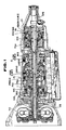
- the automatic power transmission in the shown embodiment includes a torque converter T/C associated with an output shaft of an internal combustion engine via an input shaft I/S.
- the torque converter T/C includes a lock-up mechanism for establishing lock-up.
- the torque converter T/C is housed within a converter casing which is rigidly secured to a casing K1 of the primary transmission unit A1.
- the subsidiary transmission unit A2 has a casing K2 connected to the primary transmission casing K1 in alignment.
- the primary transmission unit housed within the primary transmission casing K1 includes an input or turbine shaft I/S connected to the output shaft of an automotive internal combustion engine as a prime mover, via a torque converter T/C.
- the primary transmission unit A1 also includes an intermediate shaft M/S for transmitting driving torque to a final drive.
- the torque converter T/C has a pump impeller, a turbine rubber and a stator.
- the pump impeller is connected to the engine output shaft.
- the turbine runner is connected to the input shaft I/S.
- the pump impeller is also connected to an oil pump for driving the latter.
- the torque converter incorporates a lock-up clutch.
- the first planetary gear set PG1 includes sun gear S1, a ring gear R1, a pinion P1 and a carrier PC1 supporting the planetary gear.
- the second planetary gear set PG2 includes a sun gear S2, a ring gear R2, a pinion P2 and a carrier PC2 supporting the pinion.
- the carrier PC1 supporting the pinion P1 is so designed as to be connectively associated with the input shaft I/S via a high clutch H/C.
- the carrier PC1 is also connected to the ring gear R2 of the second planetary gear set PG2 via a forward clutch F/C and a forward one-way clutch FWD O.W.C. which is coupled with the forward clutch in series, or in the alternative, via the forward clutch F/C and a overrun clutch OVR/C which is provided in parallel to the forward one-way clutch FWD O.W.C.
- the carrier PC 1 is adapted to be anchored by a low and reverse brake L&R/B and its reverse rotation is prevented by the low one-way clutch LOW O.W.C.
- the sun gear S1 of the first planetary gear set 15 is so designed as to be connectively associated with the input shaft I/S via a reverse clutch R/C.
- the sun gear S2 of the second planetary gear set PG2 is constantly connected to the input shaft I/S.
- the ring gear R1 of the first planetary gear set PG1 and the carrier PC2 of the second planetary gear set PG2 are constantly connected to the intermediate shaft M/S.
- the ring gear R1 is integrally connected with the carrier PC2 of the second planetary gear set PG2.
- the sun gear S2 of the second planetary gear set PG2 connected to the input shaft I/S.
- the ring gear R2 is connectively associated with the carrier PC1 via the overrun clutch OVR/C.
- the forward one-way clutch FWD O.W.C and the forward clutch F/C are arranged between the carrier PC1 and the ring gear R2 of the second planetary gear set 16. Engagement of the forward clutch F/C causes the forward one-way clutch FWD O.W.C. to connect the ring gear R2 with the carrier PC1 in the reverse rotational direction.
- a low and reverse brake L&R/B can fix the carrier PC1.
- a band brake B/B can fix the sun gear S1.
- a low one-way clutch LOW O.W.C. permits rotation of the carrier PC1 in a forward direction (same direction to the rotating direction of the engine intermediate shaft M/S and prevents the carrier PC1 from rotating in reverse direction (opposite to the rotating direction in forward direction).
- the subsidiary transmission unit A2 includes a third planetary gear set PG3 which includes a sun gear S3, a ring gear R3, a pinion P3 and a pinion carrier PC3.
- the third planetary gear set PG3 of the subsidiary transmission unit A2 is housed within the subsidiary transmission casing K2.
- a direct clutch D/C, a reduction brake RDCN/B and a reduction one-way clutch RDCN O.W.C. are also housed within the subsidiary transmission casing K2.
- the reduction brake RDCN/B is arranged in parallel relationship with the reduction one-way clutch RDCN O.W.C.
- the ring gear R3 is rigidly connected to the intermediate shaft M/S for co-rotation therewith.
- the sun gear S3 is radially supported on an output shaft O/S via a sun gear bearing 2.
- the sun gear S3 is associated with the reduction brake RDCN/B so that it can be locked on the subsidiary transmission casing K2 when the latter is applied.
- the sub gear S3 is connectable with the pinion carrier PC1 via the direct clutch D/C which has a clutch drum 1 provided for co-rotation with the sun gear S3.
- the clutch drum 1 of the direct clutch D/C is associated with the reduction brake RDCN/B for locking the sun gear S3 onto the subsidiary transmission casing.
- the sun gear S3 is associated with the reduction one-way clutch RDCN O.W.C. for to be permitted rotation in forward direction and prevented rotation in the reverse direction.
- the reduction one-way clutch RDCN O.W.C. has a outer race 3 is rigidly fixed to the clutch drum 1 of the direct clutch D/C.
- the inner race 4 of the reduction one-way clutch RDCN O.W.C. is integrally formed with a support 5.
- the end portion of the clutch drum 1, which end portion is oriented in the vicinity of the sun gear S3, is supported by means of a drum bearing 6.
- the free end of the outer race 3 is supported by means of an end bearing 7.
- the clutch drum 1 has the end bent radially inward and formed with the spline section 1a.
- An attachment plate 8 is secured on the radially extended section of the clutch drum 1.
- the attachment plate 8 has the splined radial inner end 8a.
- the sun gear S3 has a helical gear teeth 9 with a spline section 9a which is formed integrally with the helical gear teeth. Both of the splined radial inner ends 1a and 8a engage with the spline section 9a with a play in axial and radial directions.
- reference numeral 10 and 11 denote thrust bearings
- 12 denotes clutch hub formed integrally with the pinion carrier PC3 of the third planetary gear set PG3
- 13 denotes a parking gear integrally formed with the pinion carrier PC3
- 14 is a clutch piston
- 15 denotes a return spring
- 16 denotes a brake piston
- 17 denotes a return spring
- 18 denote a bolt for securing the support 5 onto the subsidiary transmission casing K2.
- the rotary elements which are required to be supported by means bearings are the sun gear S3, the clutch drum 1 and the reduction one-way clutch RDCN O.W.C.
- the outer race 3 of the reduction one-way clutch RDCN O.W.C. is rigidly secured to the clutch drum 1
- the inner race of the reduction one-way clutch RDCN O.W.C. is secured to the support 5 attached to the subsidiary transmission casing K2. Therefore, the clutch drum 1 associated with the outer race 3 can be supported with respect to the support 5.
- centering of the reduction one-way clutch RDCN O.W.C. can be done with respect to one side . Therefore, the reduction one-way clutch RDCN O.W.C. also can be supported at one side. Therefore, in the shown construction, the bearings 6 and 7 can perform equivalent supporting performance to a pair of bearings required for the clutch drum and a pair of end bearings required for centering the outer race of the reduction one-way clutch in the prior art.
- sun gear S3 can be supported by means of a sole bearing 2. Furthermore, since the sun gear S3 is independent of the clutch drum 1 and the reduction one-way clutch RDCN O.W.C., accuracy required in assembling and machining the the clutch drum 1 and the reduction one-way clutch RDCN O.W.C. becomes lower.
- the power train as set forth above is selectable of power transmission mode by combination of the states of one or more friction elements, i.e. the reverse clutch R/C, the high clutch H/C, forward clutch F/C , the overrun clutch OVR/C, the low and reverse brake L&R/B and the band brake B/B, to establish various mode of operation of the components of S1, S2, S3, R1, R2, R3, PC1, PC2 and PC3 of the first, second and third planetary gear sets PG1, PG2 and PG3.
- rotation speed at the intermediate shaft M/S versus of the rotation speed at the input shaft I/S is varied at various rates.
- Fig. 4 Active components at respective operational modes of the transmission are illustrated in Fig. 4.
- the ratio of rotation of the output shaft O/S versus the rotation speed of the input shaft I/S is determined.
- a hydraulic unit 10 is mounted on the primary transmission casing K1.
- the hydraulic unit 10 on the primary transmission casing K1 forms a primary hydraulic control unit 12.
- the hydraulic unit 10 is connected to the reduction brake RDCN/B and the direct clutch D/C for supplying control pressure.
- a pressure accumulator 33 is provided for a control line 30 for supplying the control pressure to the direct clutch D/C.
- the pressure accumulator 33 is connected to the control line 30 via a flow restriction orifice 31 and an one-way check valve 32.
- These pressure accumulator 33, the flow restriction orifice 31 and the one-way check valve 32 form a subsidiary hydraulic control unit 20.
- the subsidiary hydraulic control unit 20 is mounted on the subsidiary transmission casing K2.
- the reduction brake RDCN/B is directly connected to the primary hydraulic control unit 12 for receiving the control pressure therefrom.
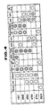
- the hydraulic system in the primary and subsidiary hydraulic control units 12 and 20 of the shown automatic power transmission, as shown in Fig. 7, is provided hydraulic pressure controlling operation of respective friction elements.
- the hydraulic system includes a pressure regulator valve 40, a pressure modifier valve 42, a line pressure solenoid 44, a modifier pressure accumulator valve 46, an accumulator shift valve 47, a pilot valve 48, a torque converter relief valve 50, a lock-up control valve 52, a lock-up solenoid 56, a manual selector valve 58, a first shift valve 60, a second shift valve 62, a first shift solenoid 64, a second shift solenoid 66, a 3-2 timing valve 70, a 5-2 relay valve 72, a 5-2 sequence valve 74, a first range reducing valve 76, a shuttle shift valve 78, an overrun clutch control valve 80, an overrun clutch solenoid 82, an overrun clutch reducing valve 84, a reducing timing valve 85, a N-D accumulator 86, a
- a 4-5 accumulator 98 and a reduction brake accumulator 100 are provided.
- the shown circuit structure has been somewhat modified from that disclosed in the above-identified publication in some aspect.
- the modified hydraulic circuit has been disclosed in Service Manual No. 626 (YA1-3, YA1B) "NISSAN CEDRIC, GLORIA, Introduction to Modification of Y31 type series" pages C-22 and C-35, issued in June, 1989, by Nissan Motor Co., Ltd.
- the disclosure of this publication is herein incorporated by reference for the sake of disclosure.
- the pressure regulator valve 40 adjusts a line pressure by modulating the source pressure from the oil pump depending upon a driving condition.
- the pressure modifier valve 42 serves for assisting the pressure regulator valve 40 and adjusts signal pressure (modifier pressure for providing adjusting line pressure depending upon the driving condition.
- the modifier accumulator valve 46 removes pulsation of the line pressure by smoothing the pressure modifier pressure supplied from the pressure modifier valve 42.
- the pilot valve 48 produces a pilot pressure for controlling line pressure, lock-up of torque converter, overrun clutch, 3-2 timing valve and so forth.
- the accumulator control valve 94 controls back pressure according to the driving condition.
- the manual selector valve 58 is associated with a manually operable selector lever and shiftable according to selector lever position for selectively distributing the line pressure for corresponding friction elements set forth above.
- the first and second shift valves 60 and 62 are associated with the first shift solenoid 64 for simultaneously switching connection of three lines for controlling shifting operation between first, second, third and fourth speed ratios.
- the second chamber and a fourth speed servo apply chamber With this construction, when second speed pressure is supplied to the second speed servo apply chamber, the band brake (B/B) 28 is applied; when the third speed pressure is supplied to the third speed servo release chamber, the band brake is released; and when the fourth speed pressure is supplied to the fourth speed servo apply chamber, the band brake is applied.
- an apply chamber and a release chamber are defined in the torque converter T/C in order to control the state of the lock-up clutch. Namely, when the fluid pressure is supplied to the release chamber, the lock-up clutch is released and when the fluid pressure is supplied to the apply chamber, lock-up clutch is engaged for establishing lock-up condition.
- the band brake B/B defines a second speed servo apply chamber, a third speed servo release chamber and a fourth speed servo apply chamber.
- the shown embodiment of the hydraulic circuit of the automatic power transmission incorporates an variable displacement vane-type oil pump 34 associated with a feedback accumulator 32.
- the hydraulic circuit further comprises an oil cooler 36, a front side lubricant line 37 and a back side lubricant line 38.
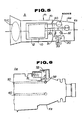
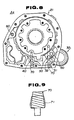
- Fig. 8 shows side elevation of the subsidiary transmission casing employed in the shown embodiment of the automatic power transmission according to the present invention.
- the reference numeral 50 denotes a drain path
- the reference numeral 60 denotes a parking pawl pin
- the reference numeral 70 denotes a plug for blocking opening.
- the plug 70 is formed into a configuration as illustrated in Fig. 9.
- sealing layer 71 is provided at a threaded portion 70a offsetting from the front end in a magnitude corresponding to two or three turns of thread. Such manner of forming of the sealing layer 71 may improve workability in assembling operation because it makes easy to initial set of the plug to the associated opening.
- the control line 30 for the direct clutch D/C, a brake pressure path 40 for the reduction brake RDCN/B and the drain path 50 in the subsidiary transmission casing K2 are aligned to the corresponding path in the primary transmission casing K1. This makes installation of the subsidiary transmission casing to the primary transmission casing K1 easier.
- the line pressure as the direct clutch control pressure is supplied through the control line 30.
- the control pressure overcomes the set pressure of a set spring of the pressure accumulator 33, the pressure accumulator start accumulation of the fluid pressure.
- the pressure increasing rate at the direct clutch D/C is reduced for eliminating shock in engagement of the direct clutch.
- the pressure accumulator 33 saturate, the control pressure to be supplied to the direct clutch D/C is increased at greater rate. This successfully prevent the direct clutch D/C from slipping.
- the pressure accumulator 33 is effective for lowering of pressure drop in the control line in a pressure range lower than the saturation pressure and set pressure. This successfully suppress down-shifting shock which otherwise caused by the reduction one-way clutch RDCN O.W.C.
- the transmission can be operated to various range positions as illustrated in Fig. 4.
- the similar construction may be applicable for supporting sun gear and associated elements in the over-drive mechanism (4th range) of the primary transmission.
- the similar supporting structure may be applicable for a laterally mounted type transmission which has parallel shafts.
Landscapes
- Engineering & Computer Science (AREA)
- General Engineering & Computer Science (AREA)
- Mechanical Engineering (AREA)
- Physics & Mathematics (AREA)
- Fluid Mechanics (AREA)
- Structure Of Transmissions (AREA)
- Control Of Transmission Device (AREA)
Applications Claiming Priority (2)
| Application Number | Priority Date | Filing Date | Title |
|---|---|---|---|
| JP330493/88 | 1988-12-26 | ||
| JP63330493A JP2683396B2 (ja) | 1988-12-26 | 1988-12-26 | 副変速機付自動変速機 |
Publications (3)
| Publication Number | Publication Date |
|---|---|
| EP0376283A2 true EP0376283A2 (de) | 1990-07-04 |
| EP0376283A3 EP0376283A3 (en) | 1990-09-19 |
| EP0376283B1 EP0376283B1 (de) | 1995-04-19 |
Family
ID=18233238
Family Applications (1)
| Application Number | Title | Priority Date | Filing Date |
|---|---|---|---|
| EP89124027A Expired - Lifetime EP0376283B1 (de) | 1988-12-26 | 1989-12-27 | Automatisches Wechselgetriebe mit einer zusätzlichen Getriebestufe |
Country Status (4)
| Country | Link |
|---|---|
| US (1) | US5090950A (de) |
| EP (1) | EP0376283B1 (de) |
| JP (1) | JP2683396B2 (de) |
| DE (1) | DE68922291T2 (de) |
Cited By (4)
| Publication number | Priority date | Publication date | Assignee | Title |
|---|---|---|---|---|
| EP0512707A3 (en) * | 1991-05-09 | 1993-09-01 | Eaton Corporation | Range shifting only fault tolerance method/system |
| EP0398344B1 (de) * | 1989-05-18 | 1996-01-17 | Nissan Motor Co., Ltd. | Sicherheitseinrichtung für Schaltsteuerung eines Hilfsgetriebes von einem automatischen Getriebe |
| US5495778A (en) * | 1991-09-13 | 1996-03-05 | Jatco Corporation | Automotive automatic transmission structure |
| EP1431613A3 (de) * | 2002-12-18 | 2007-03-14 | General Motors Corporation | Sechsgang- Doppelkupplungsgetriebefamilie mit drei Umlaufgetrieben |
Families Citing this family (5)
| Publication number | Priority date | Publication date | Assignee | Title |
|---|---|---|---|---|
| US5426991A (en) * | 1992-04-20 | 1995-06-27 | Mazda Motor Corporation | Automatic transmission |
| DE4230622A1 (de) * | 1992-09-12 | 1994-03-17 | Zahnradfabrik Friedrichshafen | Lastschaltbares Getriebe, insbesondere Zweigang-Planetengetriebe |
| US5385064A (en) * | 1992-10-23 | 1995-01-31 | Borg-Warner Automotive, Inc. | Dual clutch countershaft automatic transmission |
| JP2003194161A (ja) * | 2001-12-25 | 2003-07-09 | Aisin Aw Co Ltd | 自動変速機 |
| JP5931103B2 (ja) * | 2014-03-10 | 2016-06-08 | ファナック株式会社 | 回転テーブル |
Family Cites Families (11)
| Publication number | Priority date | Publication date | Assignee | Title |
|---|---|---|---|---|
| JPS58211920A (ja) * | 1982-06-03 | 1983-12-09 | Toyota Motor Corp | 自動変速機 |
| JPS60107424A (ja) * | 1983-11-14 | 1985-06-12 | Aisin Warner Ltd | 4輪駆動用自動変速機 |
| US4748809A (en) * | 1984-07-31 | 1988-06-07 | Aisin-Warner Limited | Hydraulic servo mechanism of automatic transmission for vehicle |
| JPS61167751A (ja) * | 1985-01-19 | 1986-07-29 | Aisin Warner Ltd | 車両用変速機の油圧制御装置 |
| JPH0621644B2 (ja) * | 1985-01-19 | 1994-03-23 | トヨタ自動車株式会社 | 変速機の制御装置 |
| EP0214467B1 (de) * | 1985-08-05 | 1991-04-10 | Nissan Motor Co., Ltd. | Niederschaltsteuerung und Motorbremskontrolle für Automatikgetriebe |
| JPS6262047A (ja) * | 1985-09-11 | 1987-03-18 | Nissan Motor Co Ltd | 自動変速機のショック軽減装置 |
| JPS62132059A (ja) * | 1985-12-04 | 1987-06-15 | Toyota Motor Corp | 車輌用自動変速機の油圧制御装置 |
| JPH0536114Y2 (de) * | 1986-07-23 | 1993-09-13 | ||
| JPH0545891Y2 (de) * | 1987-03-31 | 1993-11-29 | ||
| JP2895705B2 (ja) * | 1993-03-11 | 1999-05-24 | 大日精化工業株式会社 | モザイク荷電メンブラン及びその製造方法 |
-
1988
- 1988-12-26 JP JP63330493A patent/JP2683396B2/ja not_active Expired - Lifetime
-
1989
- 1989-12-26 US US07/456,179 patent/US5090950A/en not_active Expired - Lifetime
- 1989-12-27 DE DE68922291T patent/DE68922291T2/de not_active Expired - Lifetime
- 1989-12-27 EP EP89124027A patent/EP0376283B1/de not_active Expired - Lifetime
Cited By (4)
| Publication number | Priority date | Publication date | Assignee | Title |
|---|---|---|---|---|
| EP0398344B1 (de) * | 1989-05-18 | 1996-01-17 | Nissan Motor Co., Ltd. | Sicherheitseinrichtung für Schaltsteuerung eines Hilfsgetriebes von einem automatischen Getriebe |
| EP0512707A3 (en) * | 1991-05-09 | 1993-09-01 | Eaton Corporation | Range shifting only fault tolerance method/system |
| US5495778A (en) * | 1991-09-13 | 1996-03-05 | Jatco Corporation | Automotive automatic transmission structure |
| EP1431613A3 (de) * | 2002-12-18 | 2007-03-14 | General Motors Corporation | Sechsgang- Doppelkupplungsgetriebefamilie mit drei Umlaufgetrieben |
Also Published As
| Publication number | Publication date |
|---|---|
| EP0376283B1 (de) | 1995-04-19 |
| DE68922291D1 (de) | 1995-05-24 |
| EP0376283A3 (en) | 1990-09-19 |
| JP2683396B2 (ja) | 1997-11-26 |
| US5090950A (en) | 1992-02-25 |
| JPH02173463A (ja) | 1990-07-04 |
| DE68922291T2 (de) | 1995-08-24 |
Similar Documents
| Publication | Publication Date | Title |
|---|---|---|
| KR960015251B1 (ko) | 자동변속기의 유압제어장치 | |
| US4846765A (en) | System for controlling the pressure of oil for a continuously variable transmission | |
| US5230664A (en) | Lubricating system for automatic transmission | |
| JP2895238B2 (ja) | 車両用自動変速機の液圧制御システム | |
| JPH023076B2 (de) | ||
| US5425283A (en) | Multi-speed power transmission | |
| EP0376283B1 (de) | Automatisches Wechselgetriebe mit einer zusätzlichen Getriebestufe | |
| US5055098A (en) | Automatic power transmission with mechanism for establishing under-drive speed ratio and bearing structure therefor | |
| US5115696A (en) | Hydraulic pressure control device with parallel pressure supply passages for certain one friction engaging means | |
| US5315901A (en) | Automatic transmission with a modulated pressure converter bypass clutch priority valve circuit | |
| US5674153A (en) | Hydraulic pressure control system of an automatic transmission for vehicle | |
| US6022288A (en) | Five-speed automatic transmission and hydraulic control system thereof | |
| US4982624A (en) | Hydraulic control device for automatic transmission for vehicle having friction engaging means operative in two jumping apart speed stages | |
| KR900001638B1 (ko) | 자동변속기의 라인압제어장치 | |
| JPS6142139B2 (de) | ||
| US5012700A (en) | Hydraulic control device for automatic transmission for vehicle having clutch disengage control means independent of clutch engage control means | |
| JP2803438B2 (ja) | 自動変速機のワンウェイクラッチフリクション防止装置 | |
| EP0745789B1 (de) | Verfahren zum Steuern des Hydraulikdrucks in automatischen Getrieben für Kraftfahrzeuge | |
| US5807208A (en) | Hydraulic control system of an automatic transmission for a vehicle | |
| JP2658228B2 (ja) | 車輌用自動変速機の油圧制御装置 | |
| JPH0792146B2 (ja) | 自動変速機の液圧制御装置 | |
| KR100422524B1 (ko) | 자동변속기의 윤활장치 | |
| JP2897992B2 (ja) | 自動変速機 | |
| JPH0765667B2 (ja) | ロックアップクラッチ付きトルクコンバータの油圧制御装置 | |
| KR950011261B1 (ko) | 자동차용 자동 변속기 |
Legal Events
| Date | Code | Title | Description |
|---|---|---|---|
| PUAI | Public reference made under article 153(3) epc to a published international application that has entered the european phase |
Free format text: ORIGINAL CODE: 0009012 |
|
| 17P | Request for examination filed |
Effective date: 19891227 |
|
| AK | Designated contracting states |
Kind code of ref document: A2 Designated state(s): DE FR GB |
|
| PUAL | Search report despatched |
Free format text: ORIGINAL CODE: 0009013 |
|
| AK | Designated contracting states |
Kind code of ref document: A3 Designated state(s): DE FR GB |
|
| 17Q | First examination report despatched |
Effective date: 19921028 |
|
| RBV | Designated contracting states (corrected) |
Designated state(s): DE GB |
|
| GRAA | (expected) grant |
Free format text: ORIGINAL CODE: 0009210 |
|
| AK | Designated contracting states |
Kind code of ref document: B1 Designated state(s): DE GB |
|
| REF | Corresponds to: |
Ref document number: 68922291 Country of ref document: DE Date of ref document: 19950524 |
|
| PLBE | No opposition filed within time limit |
Free format text: ORIGINAL CODE: 0009261 |
|
| STAA | Information on the status of an ep patent application or granted ep patent |
Free format text: STATUS: NO OPPOSITION FILED WITHIN TIME LIMIT |
|
| 26N | No opposition filed | ||
| REG | Reference to a national code |
Ref country code: GB Ref legal event code: IF02 |
|
| REG | Reference to a national code |
Ref country code: GB Ref legal event code: 732E |
|
| PGFP | Annual fee paid to national office [announced via postgrant information from national office to epo] |
Ref country code: DE Payment date: 20081229 Year of fee payment: 20 |
|
| PGFP | Annual fee paid to national office [announced via postgrant information from national office to epo] |
Ref country code: GB Payment date: 20081224 Year of fee payment: 20 |
|
| REG | Reference to a national code |
Ref country code: GB Ref legal event code: PE20 Expiry date: 20091226 |
|
| PG25 | Lapsed in a contracting state [announced via postgrant information from national office to epo] |
Ref country code: GB Free format text: LAPSE BECAUSE OF EXPIRATION OF PROTECTION Effective date: 20091226 |