EP0376308A2 - Appareil d'alimentation en feuilles - Google Patents
Appareil d'alimentation en feuilles Download PDFInfo
- Publication number
- EP0376308A2 EP0376308A2 EP89124076A EP89124076A EP0376308A2 EP 0376308 A2 EP0376308 A2 EP 0376308A2 EP 89124076 A EP89124076 A EP 89124076A EP 89124076 A EP89124076 A EP 89124076A EP 0376308 A2 EP0376308 A2 EP 0376308A2
- Authority
- EP
- European Patent Office
- Prior art keywords
- sheet
- stacking
- feeding
- directed toward
- shifting
- Prior art date
- Legal status (The legal status is an assumption and is not a legal conclusion. Google has not performed a legal analysis and makes no representation as to the accuracy of the status listed.)
- Granted
Links
Images


Classifications
-
- B—PERFORMING OPERATIONS; TRANSPORTING
- B65—CONVEYING; PACKING; STORING; HANDLING THIN OR FILAMENTARY MATERIAL
- B65H—HANDLING THIN OR FILAMENTARY MATERIAL, e.g. SHEETS, WEBS, CABLES
- B65H7/00—Controlling article feeding, separating, pile-advancing, or associated apparatus, to take account of incorrect feeding, absence of articles, or presence of faulty articles
- B65H7/02—Controlling article feeding, separating, pile-advancing, or associated apparatus, to take account of incorrect feeding, absence of articles, or presence of faulty articles by feelers or detectors
-
- B—PERFORMING OPERATIONS; TRANSPORTING
- B65—CONVEYING; PACKING; STORING; HANDLING THIN OR FILAMENTARY MATERIAL
- B65H—HANDLING THIN OR FILAMENTARY MATERIAL, e.g. SHEETS, WEBS, CABLES
- B65H3/00—Separating articles from piles
- B65H3/02—Separating articles from piles using friction forces between articles and separator
- B65H3/06—Rollers or like rotary separators
- B65H3/0669—Driving devices therefor
-
- B—PERFORMING OPERATIONS; TRANSPORTING
- B65—CONVEYING; PACKING; STORING; HANDLING THIN OR FILAMENTARY MATERIAL
- B65H—HANDLING THIN OR FILAMENTARY MATERIAL, e.g. SHEETS, WEBS, CABLES
- B65H2511/00—Dimensions; Position; Numbers; Identification; Occurrences
- B65H2511/20—Location in space
-
- B—PERFORMING OPERATIONS; TRANSPORTING
- B65—CONVEYING; PACKING; STORING; HANDLING THIN OR FILAMENTARY MATERIAL
- B65H—HANDLING THIN OR FILAMENTARY MATERIAL, e.g. SHEETS, WEBS, CABLES
- B65H2511/00—Dimensions; Position; Numbers; Identification; Occurrences
- B65H2511/50—Occurence
- B65H2511/51—Presence
-
- B—PERFORMING OPERATIONS; TRANSPORTING
- B65—CONVEYING; PACKING; STORING; HANDLING THIN OR FILAMENTARY MATERIAL
- B65H—HANDLING THIN OR FILAMENTARY MATERIAL, e.g. SHEETS, WEBS, CABLES
- B65H2515/00—Physical entities not provided for in groups B65H2511/00 or B65H2513/00
- B65H2515/30—Forces; Stresses
Definitions
- the present invention relates to a sheet feeding apparatus adapted to feed a sheet to an image forming portion of an image reading portion of an image processing system such as a copying machine, facsimile, printer and the like.
- a solenoid was used (as disclosed in the Japanese Patent Laid-Open No. 48-96023) or a cam was used (as disclosed in the Japanese Patent Publication No. 62-19330).
- the conventional apparatuses use the clutches or solenoids in order to ensure the rotation of the pick-up roller and the separation of the pick-up roller from the sheet, and, thus, have the following problems:
- the U.S. Patent No. 4,262,894 and the Japanese Patent Laid-Open No. 60-204566 disclose a sheet feeding apparatus wherein a pick-up roller is attached to a pivotable arm and the pivotable arm arm is pivoted or rocked by a motor through a friction clutch so that the arm is shifted toward and away from the sheet.
- the friction clutch is so designed that a required torque can be transmitted to the pick-up roller when the pick-up roller is lifted (i.e., separated from the sheet).
- the present invention aims to solve the above-mentioned conventional problems, and, accordingly, an object of the present invention is to provide a sheet feeding apparatus which has a simple construction and wherein the control therefor is simplified and the whole load is small.
- Another object of the present invention is to provide a sheet feeding apparatus wherein the number of driving sources is minimized, the loss of the driving force is reduced, the apparatus itself is compacted, and the consumption of electric power is reduced.
- the other object of the present invention is to provide a sheet feeding apparatus which does not need the complicated control.
- the present invention is explained as examples that the invention is applied to an automatic original feeding apparatus, but the present invention is not limited to such original feeding apparatus, and can be applied to a sheet feeding apparatus for feeding any sheet.
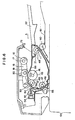
- Fig. 1 is a sectional view of an automatic original feeding apparatus
- Fig. 2 is a perspective view of the original feeding apparatus
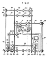
- Fig. 3 shows a driving mechanism for the original feeding apparatus.
- the reference numeral 22 denotes a driving shaft which can be rotated by the driving force from the pulley 4; 23 denotes a gear attached to the driving shaft 22; 24 denotes a gear meshed with the gear 23; 25 denotes a gear meshed with the gear 24 and fixed to the ejector roller shaft 11; and 15a, 15b denote one-way clutches each of which can transmit a rotational force only in one direction and can be slipped in the other direction. These one-way clutches 15a, 15b are arranged on the ejector roller shaft 11.
- the reference numeral 26 denotes a pulley fixed to the ejector roller shaft 11 to be rotated in the same direction as the gear 6; 27 denotes a belt for transmitting the rotation of the pulley 26 to a pulley 28 which is connected to a shaft 20 of sheet feed rollers 19 through a one-way clutch 15c; 29 denotes a pulley fixedly mounted on the feed roller shaft 20; and 30 denotes a belt for transmitting the rotation of the pulley 29 to a pulley 31 fixed to the pick-up roller shaft 17.
- the reference numeral 32 denotes a gear fixed to the ejector roller shaft 11 to be rotated in the same direction as the shaft 11; 33 denotes a gear meshed with the gear 32; 34 dentoes a pulley mounted to be rotated in the same direction as the gear 33; 35 dentoes a belt for transmitting the rotation of the pulley 34 to a pulley 36 fixed to a transmission shaft 37; 38 denotes a pulley fixed to the transmission shaft 37 for transmitting the rotation of the transmisstion shaft 37 to a pulley 40 through a belt 39, which pulley 40 is fixed to a separation driving shaft 41; 42 denotes a torque limiter attached to the separation driving shaft 41, which torque limiter acts to transmit the rotational force of the separation driving shaft by a predetermined amount thereof or less; and 43 denotes reverse rollers.
- the reference numeral 44 denotes a pulley attached to the ejector roller shaft 11 to be rotated in the same direction as the shaft 11; 45 denotes a belt for transmitting the rotation of the pulley 44 to pulleys 46 fixed to shafts 47 of conveying rollers 48; 49 denotes ejector rollers; 50 denotes an actuator means for lifting and lowering the pick-up rollers 16; 51 denotes an original detecting lever arranged at an upstream side (right in Fig. 1) of an original feeding direction and rotated around the rocking shaft 13, and 52 denotes an original detecting sensor for detecting the presence of the original 1 by detecting the posture of the detecting lever 51.
- the detecting sensor 52 may comprise a magnetic sensor, a microswitch or the like.
- the original detecting lever 51 fixed to the rocking shaft 13 is rotated around the rocking shaft 13 by a pushing force from the leading edge of the original, whereby the original detecting sensor 52 judges that the original is present. Consequently, the motor 2 is rotated in a reverse direction (direction shown by the broken arrow in Fig. 2), so that the driving force of the motor is transmitted to the gear 6 through the belt 3, pulley 4 and gear 5, and then is transmitted to the ejector roller shaft 11 through the one-way clutch 15a. On the other hand, the driving force of the motor 2 is also transmitted from the pulley 4 to the driving shaft 22 and then is transmitted to the gear 25 through the gears 23, 24.
- the one-way clutch 15b since the one-way clutch 15b is slipped, the latter driving force cannot be transmitted to the ejector roller shaft 11.
- opposite driving forces are transmitted to the ejector roller shaft 11 at both ends thereof, since there are arranged one-way clutches 15a, 15b on both ends of the shaft 11, only one of the opposite driving forces is transmitted to the shaft 11 through the one of the one-way clutches, whereas the other driving force is not transmitted to the shaft 11 due to the slip of the other one-way clutch. Accordingly, the ejector roller shaft 11 is rotated always in one direction.
- the pick-up rollers 16 are begun to contact the original 1 and feed the same while rotating in the original feeding direction.
- the rotation of the ejector roller shaft 11 is transmitted to the reverse rollers or separating rollers 43 through the gears 32, 33, pulley 34, belt 35, pulley 36, transmission shaft 37, pulley 38, belt 39, pulley 40, separation driving shaft 41 and torque limiter 42. Further, the rotation of the ejector roller shaft 11 is also transmitted to the conveying rollers 48 through the pulley 44, belt 45, pulleys 46 and conveying roller shafts 47.
- the original 1 is fed to a separating portion constituted by the feed rollers 19, separating rollers 43 and the like.
- the original 1 separated one by one by the feed rollers 19 and the separating rollers 43 is conveyed by the conveying rollers 48 and counter rollers 53.
- an original tip end detecting lever 54 When the leading edge of the original rotates an original tip end detecting lever 54 around a pivot shaft 55, an original tip end detecting sensor 56 is turned OFF, thus detecting the tip end of the original.
- the original tip end detecting lever 54 is biased by a spring 57 so that the free end of the lever 54 is abutted against a hole 59 formed in an original guide 58.
- a rocking range of the rocking plate 12 is limited by a stopper 21 so that, when the rocking plate 12 abuts against the stopper 21, the friction pad 7 and friction link 8 are slipped not to transmit the driving force to the rocking shaft 13.
- the rotational direction of the motor is reversed, thereby separating the pick-up rollers 16 from the original 1.
- the separating rollers 43 rotated by the ejector roller shaft 11 through the gears 32, 33, pulley 34, belt 35, pulley 36, transmission shaft 37, pulley 38, belt 39, pulley 40, separation driving shaft 41 and torque limiter 42, the conveying rollers 48 rotated through the pulley 44, belt 45, pulley 46 and conveying roller shaft 44, and the ejector rollers 40 are rotated in a given direction, respectively, regardless of the rotational direction of the motor 2.
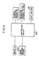
- an image reading device 100 starts to read an image on the original.
- this lever 54 is rotated around the pivot shaft 55 by the spring 57, whereby the free end of the lever is abutted against the hole 59 of the original guide 58, thereby turning the original tip end detecting sensor 56 ON.
- a further predetermined time t1 is elapsed, the reading of the image is completed.
- the motor 2 is stopped. Since the original sensor 52 is kept in On condition so long as there is the original 1 in a supply tray 62, the motor 2 is driven to repeat the above-mentioned operation until there is no original 1 in the supply tray 62 and the original sensor 52 is turned OFF.
- the reference numeral 90 denotes a control circuit.
- a step S1 if the original sensor 52 is turned OFF, the sensor judges the absence of the original, and the original feeding operation is not initiated, and the sequence returns to START. On the other hand, if the original sensor 52 is turned ON, the sequence goes to a step S2, where, if the original tip end detecting sensor 56 is turned OFF, it is judged that any original remains in the original feeding path, and the sequence returns to the START.
- step S3 If the original sensor is turned ON (presence of original) and the original tip end detecting sensor 56 is also turned ON (none of jammed original), the sequence goes to a step S3, where the original feeding operation is started, and the motor 2 is rotated in the reverse direction for a predetermined time to lift the pick-up rollers 16.
- step S5 when the start button (not shown) is depressed, the motor is rotated in the normal direction to lower the pick-up rollers (in a step S6), thus starting the feeding of the original.
- the original tip end detecting sensor 56 is turned ON (in a step S12), and a timer 2 is set (in a step S13). After the fact that a predetermined time t2 is elasped is confirmed by the timer 2 (in a step S14), the reading of the image by means of the image reading device 100 is finished. Further, after the predetermined time t2 has been elasped, the motor 2 is stopped (in a step S17).
- the sequence returns to the step S2, where the original feeding operation is again started, and this feeding operation is repeated until the original sensor 52 is turned OFF. If the power source is shut off, for example, due to power stoppage, before the original 1 is detected by the original tip end detecting sensor 56 after the pick-up rollers 16 have been lowered and the original feeding operation has been started, the original 1 trapped in the original feeding path is removed. When the power source is restored (turned ON), the sequence returns to the step S1. When the original 1 is introduced into the entrance A, the original 1 is detected by the original sensor 52, the rotating the motor in the reverse direction (shown by the broken arrow in Fig. 2) to lift the pick-up rollers 16 to fully open the entrance A, thus ensuring a smooth insertion of the original 1.
- step S1 the absence of the original is judged, the sequence returns to the START. Further, in the step S2, the jamming of the original is detected, the sequence returns to the START. Accordingly, until the jammed original is removed, the sequence will reciprocate between the step S2 and the START repeatedly. If the jammed original is removed, the sequence goes from the step S2 to the step S3.
- a step S7a if the original tip end detecting sensor is not turned OFF by a predetermined time t3 after the motor has been rotated in the normal direction to start the feeding of the original, that is to say, if the original does not reach the original tip end detecting sensor, it is considered to occur the jamming of the original, and the sequence returns to the START. Then, the sequence goes to the steps S1-S3, thereby lifting the pick-up rollers 16, whereby the apparatus becomes a waiting condition in the step S5. Accordingly, by removing the jammed original in the waiting condition, when the start button is depressed again, the routine on and after the step S6 is executed normally as it is.
- a step S12a if the trailing edge of the original is not passed through the original end tip detecting sensor by a predetermined time t4 after the motor has been rotated in the reverse direction, it is considered to occur the jamming of the original, and the sequence returns to the START. Also in this case, the sequence goes to the step S2, and then is repeated between the step S2 and the START, whereby the apparatus becomes a waiting condition, while the pick-up rollers 16 remain in the lifted condition.
- the sequence when the jamming of the original occurs, the sequence always returns to the START, and when the jammed original is removed to restore the normal condition, the further sequence or routine is executed normally. Accordingly, it is needless to depress a reset button or to detect the completion of the jamming treatment by detecting the opening of a cover or guide members.
- the pick-up rollers 16 are lifted. Accordingly, if the apparatus is stopped while the pick-up rollers 16 remain in the lowered condition, due to the abnormity such as the power stoppage, power OFF and the like, it is no problem even when the originals remain in the supply tray 62, or even when the originals are re-stacked or new originals are stacked in the supply tray 62 since as it is intended to supply the new original in the supply tray the pick-up rollers 16 are lifted.
- the present invention can be applied for feeding transfer papers to be copied, print papers and the like, other than the originals. Therefore, in this disclosure, the original, transfer paper, copy paper, print paper and the like are generically referred as "sheet” (or “sheet material”).
- a photodetector comprising a light emitter 71 and a light receiver 72 is arranged in the entrance A, in place of the original sensor 52.
- a light path from the light emitter 71 to the light receiver 72 is interrupted by the original, thereby detecting the presence the original 1, whereby the motor 2 is driven.
- the operation of the sheet feeding apparatus according to the second embodiment is substantially the same as that of the previous or first embodiment.
- the rocking plate 12 is made of elastic material having a spring feature so that the rocking plate 12 itself is pressed against the friction pad 7.
- the friction link 8 is omitted.
- the rotation of the gear 6 is transmitted directly from the friction pad 7 to the rocking plate 12, thus converting the rotational movement of the gear 6 into a reciprocal movement of the rocking plate.
- the reciprocal movement of the rocking plate 12 is converted into the up-and-down movement of the pick-up rollers 16 through the rocking shaft 13, support plates 14 and arm 18.
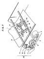
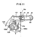
- Figs. 8 to 11 show a further embodiment wherein a means for transmitting the driving force to the support plates 14 is altered.
- the reference numeral 108 denotes a rocking arm rotatably mounted on the ejector roller shaft 11, which rocking arm 108 is connected to the gear 6 through a spring clutch 109.
- the spring clutch 109 When the gear 6 is rotated in a direction I (Fig. 8), the spring clutch 109 is placed under a tensioned condition, thus transmitting the driving force to the rocking arm 108.
- the gear 6 is rotated in a direction II (Fig. 8)
- the spring clutch 109 is placed under a slacked condition, whereby the spring clutch is idly driven while affecting a slight release torque to the rocking arm 108.
- the reference numeral 13 denotes a rocking shaft rotatably supported by a frame of the apparatus; and 112 denotes a rocking member attached to the rocking shaft 13.
- a pin 108a formed on the rocking arm 108 can slide while abutting against an end face 112a of the rocking member 112, thus rocking the rocking member 112. Consequently, the support plate 14 fixed to the rocking shaft 13 are rocked.
- the spring clutch 109 comprises a first drum 109b fixed to the gear 6, a second drum 109c fixed to the rocking arm 108, and a coil spring 109d wound around the first and second drums 109b, 109c.
- the coil spring 109d tightens the first and second drums 109b, 109c to rotate therewith, thereby transmitting the torque.
- the coil spring 109d is slacked, and, thus, the coil spring contacts the first and second drums only by the spring force of the coil spring itself, whereby the coil spring transmits a small torque to the drums or slips on the drums.
- the original detecting lever 51 attached to the rocking shaft 13 is rotated in an anti-clockwise direction, whereby the original sensor 52 detects the presence of the original, thereby rotating the pulse motor 2 in the reverse direction corresponding to the direction I.
- the rotation of the pulse motor 2 is transmitted to the gear 6 through the belt 3, pulley 4 and gear 5.
- the spring clutch 109 which can transmit the driving force only in this direction, the rotation of the gear 6 is transmitted to the rocking arm 108, thus rotating the latter in a clockwise direction, whereby the rocking member 112 is rotated in a direction where the support plates 14 fixed to the rocking shaft 13 are lifted. Consequently, the arms 18 are also lifted, thus shifting the pick-up rollers 16 supported by the arms 18 to a retarded position (position shown by the solid line in Fig. 11).
- the start button (not shown) is depressed.
- the control portion receiving a start signal from the start button activates the pulse motor 2 to rotate the belt 3 in the normal direction corresponding to the direction II.
- the rotation of the pulse motor 2 is transmitted to the gear 6 through the belt 3, pulley 4 and gear 5.
- the spring clutch 109 is idly driven while transmitting the driving force of the gear 6 to the rocking arm 108 only by a small torque amount.
- the weight of the pick-up rollers acts on the rocking member 112 so that the rocking member is rotated in the direction II through the support plates 14 and the rocking shaft 13.
- the lifting of the pick-up rollers 16 can be effected with the least driving force and the lowering of the pick-up rollers 16 can be effected by the small torque in the slacked condition of the spring clutch 109 and the weight of the pick-up rollers 16 themselves. Accordingly, the load acting on the pulse motor 2 can be minimized, and the loss of energy can be prevented unlike the case where the friction clutch is used for converting the driving energy into thermal energy.
- the present invention provides a sheet feeding apparatus comprising a stacking means for stacking sheets; a feed means for feeding the sheets stacked in the stacking means; a driving means for generating rotational forces in a predetermined direction and in an opposite direction opposite to the predetermined direction; and a shifting means for shifting the feed means to a position where the feed means contacts the sheet stacked in the stacking means by the rotational force directed toward the predetermined direction, and for separating the feed means from the sheet stacked in the stacking means by the rotational force directed toward the opposite direction.
- the shifting means includes a driving force transmitting means for transmitting the rotational force directed toward the predetermined direction by a first predetermined value and for transmitting the rotational force directed toward the opposite direction by a second predetermined value, whereby the feed means is shifted by the rotational force transmitted by the driving force transmitting means.
Landscapes
- Engineering & Computer Science (AREA)
- Mechanical Engineering (AREA)
- Sheets, Magazines, And Separation Thereof (AREA)
Applications Claiming Priority (6)
| Application Number | Priority Date | Filing Date | Title |
|---|---|---|---|
| JP33264488A JPH02178127A (ja) | 1988-12-28 | 1988-12-28 | シート給送装置 |
| JP332644/88 | 1988-12-28 | ||
| JP63330984A JP2614296B2 (ja) | 1988-12-29 | 1988-12-29 | シート自動供給装置 |
| JP330985/88 | 1988-12-29 | ||
| JP33098588A JPH0659944B2 (ja) | 1988-12-29 | 1988-12-29 | 原稿自動供給装置 |
| JP330984/88 | 1988-12-29 |
Publications (3)
| Publication Number | Publication Date |
|---|---|
| EP0376308A2 true EP0376308A2 (fr) | 1990-07-04 |
| EP0376308A3 EP0376308A3 (fr) | 1991-09-18 |
| EP0376308B1 EP0376308B1 (fr) | 1997-04-16 |
Family
ID=27340444
Family Applications (1)
| Application Number | Title | Priority Date | Filing Date |
|---|---|---|---|
| EP89124076A Expired - Lifetime EP0376308B1 (fr) | 1988-12-28 | 1989-12-28 | Appareil d'alimentation en feuilles |
Country Status (2)
| Country | Link |
|---|---|
| EP (1) | EP0376308B1 (fr) |
| DE (1) | DE68927976T2 (fr) |
Cited By (2)
| Publication number | Priority date | Publication date | Assignee | Title |
|---|---|---|---|---|
| EP0482617A1 (fr) * | 1990-10-24 | 1992-04-29 | Canon Kabushiki Kaisha | Appareil d'alimentation en feuilles |
| EP1215536A1 (fr) * | 2000-12-18 | 2002-06-19 | Ricoh Company, Ltd. | Dispositif automatique d'alimentation de documents et appareil de formation d'images correspondant |
Family Cites Families (3)
| Publication number | Priority date | Publication date | Assignee | Title |
|---|---|---|---|---|
| US3567214A (en) * | 1968-06-10 | 1971-03-02 | Xerox Corp | Sheet feeding and separating apparatus |
| US4085931A (en) * | 1977-03-28 | 1978-04-25 | Veeder Industries Inc. | Document actuated interlock mechanism |
| JPH01156241A (ja) * | 1987-12-10 | 1989-06-19 | Matsushita Electric Ind Co Ltd | 給紙装置 |
-
1989
- 1989-12-28 DE DE1989627976 patent/DE68927976T2/de not_active Expired - Fee Related
- 1989-12-28 EP EP89124076A patent/EP0376308B1/fr not_active Expired - Lifetime
Cited By (3)
| Publication number | Priority date | Publication date | Assignee | Title |
|---|---|---|---|---|
| EP0482617A1 (fr) * | 1990-10-24 | 1992-04-29 | Canon Kabushiki Kaisha | Appareil d'alimentation en feuilles |
| US5219155A (en) * | 1990-10-24 | 1993-06-15 | Canon Kabushiki Kaisha | Sheet feeding apparatus |
| EP1215536A1 (fr) * | 2000-12-18 | 2002-06-19 | Ricoh Company, Ltd. | Dispositif automatique d'alimentation de documents et appareil de formation d'images correspondant |
Also Published As
| Publication number | Publication date |
|---|---|
| DE68927976T2 (de) | 1997-11-06 |
| DE68927976D1 (de) | 1997-05-22 |
| EP0376308B1 (fr) | 1997-04-16 |
| EP0376308A3 (fr) | 1991-09-18 |
Similar Documents
| Publication | Publication Date | Title |
|---|---|---|
| US5209465A (en) | Sheet feeding apparatus | |
| US4717139A (en) | Sheet feeding apparatus | |
| EP0314167B1 (fr) | Dispositif d'alimentation de feuilles | |
| EP0409203B1 (fr) | Appareil d'alimentation en feuilles | |
| EP0774434B1 (fr) | Appareil pour alimenter des feuilles | |
| EP0761581B1 (fr) | Dispositif d'alimentation de feuilles | |
| EP0576035B1 (fr) | Dispositif d'alimentation de feuilles | |
| EP0994051A2 (fr) | Dispositif d'alimentation en feuilles, appareil de formation d'images avec un tel dispositif et appareil pour lire des images avec un tel dispositif | |
| JP3378327B2 (ja) | シート分離装置 | |
| US5076563A (en) | Apparatus for controlling a sheet supplying device | |
| US6098536A (en) | Stencil printer | |
| US6042099A (en) | Sheet feeding apparatus | |
| US5527030A (en) | Recording paper sorting and discharging device | |
| US6609707B1 (en) | Sheet feeding apparatus, and image forming apparatus and image reading apparatus provided with sheet feeding apparatus | |
| EP0376308B1 (fr) | Appareil d'alimentation en feuilles | |
| JP2614296B2 (ja) | シート自動供給装置 | |
| US5551684A (en) | Sheet-material automatic feeding device | |
| JPH11222335A (ja) | シ−ト材搬送装置および画像形成装置 | |
| JP2619959B2 (ja) | 給紙装置 | |
| JPH05316303A (ja) | 画像読取装置 | |
| JP3040640B2 (ja) | シート材給送装置 | |
| JP3913485B2 (ja) | 給紙装置、シート搬送装置、画像読取装置、ならびに画像形成装置 | |
| JP3087313B2 (ja) | 給紙装置 | |
| JP3554127B2 (ja) | シート給送装置及び画像形成装置 | |
| JPH0573658B2 (fr) |
Legal Events
| Date | Code | Title | Description |
|---|---|---|---|
| PUAI | Public reference made under article 153(3) epc to a published international application that has entered the european phase |
Free format text: ORIGINAL CODE: 0009012 |
|
| AK | Designated contracting states |
Kind code of ref document: A2 Designated state(s): DE FR GB |
|
| 17P | Request for examination filed |
Effective date: 19901221 |
|
| PUAL | Search report despatched |
Free format text: ORIGINAL CODE: 0009013 |
|
| AK | Designated contracting states |
Kind code of ref document: A3 Designated state(s): DE FR GB |
|
| 17Q | First examination report despatched |
Effective date: 19930401 |
|
| GRAG | Despatch of communication of intention to grant |
Free format text: ORIGINAL CODE: EPIDOS AGRA |
|
| GRAH | Despatch of communication of intention to grant a patent |
Free format text: ORIGINAL CODE: EPIDOS IGRA |
|
| GRAH | Despatch of communication of intention to grant a patent |
Free format text: ORIGINAL CODE: EPIDOS IGRA |
|
| GRAA | (expected) grant |
Free format text: ORIGINAL CODE: 0009210 |
|
| AK | Designated contracting states |
Kind code of ref document: B1 Designated state(s): DE FR GB |
|
| REF | Corresponds to: |
Ref document number: 68927976 Country of ref document: DE Date of ref document: 19970522 |
|
| ET | Fr: translation filed | ||
| PLBE | No opposition filed within time limit |
Free format text: ORIGINAL CODE: 0009261 |
|
| STAA | Information on the status of an ep patent application or granted ep patent |
Free format text: STATUS: NO OPPOSITION FILED WITHIN TIME LIMIT |
|
| 26N | No opposition filed | ||
| REG | Reference to a national code |
Ref country code: GB Ref legal event code: IF02 |
|
| PGFP | Annual fee paid to national office [announced via postgrant information from national office to epo] |
Ref country code: FR Payment date: 20071210 Year of fee payment: 19 Ref country code: GB Payment date: 20071227 Year of fee payment: 19 |
|
| PGFP | Annual fee paid to national office [announced via postgrant information from national office to epo] |
Ref country code: DE Payment date: 20071220 Year of fee payment: 19 |
|
| GBPC | Gb: european patent ceased through non-payment of renewal fee |
Effective date: 20081228 |
|
| REG | Reference to a national code |
Ref country code: FR Ref legal event code: ST Effective date: 20090831 |
|
| PG25 | Lapsed in a contracting state [announced via postgrant information from national office to epo] |
Ref country code: DE Free format text: LAPSE BECAUSE OF NON-PAYMENT OF DUE FEES Effective date: 20090701 |
|
| PG25 | Lapsed in a contracting state [announced via postgrant information from national office to epo] |
Ref country code: GB Free format text: LAPSE BECAUSE OF NON-PAYMENT OF DUE FEES Effective date: 20081228 |
|
| PG25 | Lapsed in a contracting state [announced via postgrant information from national office to epo] |
Ref country code: FR Free format text: LAPSE BECAUSE OF NON-PAYMENT OF DUE FEES Effective date: 20081231 |