EP0376320A1 - Ferrure de renvoi, réglable en hauteur, pour ceintures de sécurité de véhicule - Google Patents
Ferrure de renvoi, réglable en hauteur, pour ceintures de sécurité de véhicule Download PDFInfo
- Publication number
- EP0376320A1 EP0376320A1 EP89124091A EP89124091A EP0376320A1 EP 0376320 A1 EP0376320 A1 EP 0376320A1 EP 89124091 A EP89124091 A EP 89124091A EP 89124091 A EP89124091 A EP 89124091A EP 0376320 A1 EP0376320 A1 EP 0376320A1
- Authority
- EP
- European Patent Office
- Prior art keywords
- locking lever
- lever
- latching
- deflection fitting
- fitting according
- Prior art date
- Legal status (The legal status is an assumption and is not a legal conclusion. Google has not performed a legal analysis and makes no representation as to the accuracy of the status listed.)
- Granted
Links
- 230000006835 compression Effects 0.000 claims abstract description 16
- 238000007906 compression Methods 0.000 claims abstract description 16
- 230000000903 blocking effect Effects 0.000 claims abstract description 5
- 230000001133 acceleration Effects 0.000 claims description 10
- 238000006073 displacement reaction Methods 0.000 claims description 4
- 238000001746 injection moulding Methods 0.000 claims 1
- 239000011324 bead Substances 0.000 description 2
- 238000002347 injection Methods 0.000 description 2
- 239000007924 injection Substances 0.000 description 2
- 238000000034 method Methods 0.000 description 2
- 230000004913 activation Effects 0.000 description 1
- 230000015572 biosynthetic process Effects 0.000 description 1
- 238000010276 construction Methods 0.000 description 1
- 230000000694 effects Effects 0.000 description 1
- 238000004519 manufacturing process Methods 0.000 description 1
- 230000000284 resting effect Effects 0.000 description 1
- 230000000717 retained effect Effects 0.000 description 1
Images

Classifications
-
- B—PERFORMING OPERATIONS; TRANSPORTING
- B60—VEHICLES IN GENERAL
- B60R—VEHICLES, VEHICLE FITTINGS, OR VEHICLE PARTS, NOT OTHERWISE PROVIDED FOR
- B60R22/00—Safety belts or body harnesses in vehicles
- B60R22/18—Anchoring devices
- B60R22/20—Anchoring devices adjustable in position, e.g. in height
- B60R22/201—Anchoring devices adjustable in position, e.g. in height with the belt anchor connected to a slider movable in a vehicle-mounted track
- B60R22/202—Anchoring devices adjustable in position, e.g. in height with the belt anchor connected to a slider movable in a vehicle-mounted track the slider comprising spring-actuated locking means
- B60R22/203—Anchoring devices adjustable in position, e.g. in height with the belt anchor connected to a slider movable in a vehicle-mounted track the slider comprising spring-actuated locking means the locking means being movably mounted on the slider
-
- B—PERFORMING OPERATIONS; TRANSPORTING
- B60—VEHICLES IN GENERAL
- B60R—VEHICLES, VEHICLE FITTINGS, OR VEHICLE PARTS, NOT OTHERWISE PROVIDED FOR
- B60R22/00—Safety belts or body harnesses in vehicles
- B60R22/18—Anchoring devices
- B60R22/20—Anchoring devices adjustable in position, e.g. in height
- B60R22/201—Anchoring devices adjustable in position, e.g. in height with the belt anchor connected to a slider movable in a vehicle-mounted track
- B60R22/205—Anchoring devices adjustable in position, e.g. in height with the belt anchor connected to a slider movable in a vehicle-mounted track the slider comprising emergency actuated locking means
Definitions
- the invention relates to a height-adjustable deflection fitting for seat belts of motor vehicles with a slide-like part which is guided in a longitudinally displaceable manner in a guide groove formed by parallel webs of a rail held fixed to the vehicle and in which a locking lever acted upon by a compression spring is pivotably mounted about its axis carrying the deflection fitting, with a longitudinally extending part Web part of the rail spaced-apart locking openings, in each of which a locking projection of the locking lever can engage to block it relative to the rail and with a device for releasing the blocking.
- the compression spring normally keeps the locking projection of the locking lever out of engagement with the locking openings.
- the locking lever is pulled down and swung out in the direction of the latching openings, so that the latching projection engages in the next latching opening in a blocking manner.
- the known deflection fitting is therefore normally not anchored in relation to the rail, which is usually attached to the so-called B-post of the vehicle.
- the height adjustment takes place in the known deflection fitting by a Bowden cable depending on the seat adjustment, the Bowden cable being extendable against the force of a spring, so that the locking lever on the Pulling forces acting on the shoulder belt, which overcome the resilient holding force of the Bowden cable and the force of the compression spring acting on the locking lever, come into locking engagement with a latching opening.
- the object of the invention is to provide a simply constructed and functionally reliable deflection fitting of the type mentioned, which can be adjusted by hand to the size of the person to be secured.
- this object is achieved with a deflection fitting of the generic type in that the compression spring acts on the locking lever in the direction of the engagement position of the locking projection in a locking opening, that the locking lever has lateral circular-shaped parts, the curved outer sides of which are concentric with the axis carrying the deflection fitting, that the diameter of the circular disk-shaped area of the locking lever corresponds to the distance between the webs delimiting the guide groove and that an actuating device is provided with which the locking lever can be pivoted out of engagement with the latching openings.
- the deflection fitting is provided with particularly simple and functionally reliable parts for its height adjustment.
- the essential part of the adjustment mechanism is formed by the locking lever, which is supported in its locking position on the one hand by the locking projection in a locking opening of the adjustment rail and on the other hand is held with its lateral circular-shaped parts directly between the parallel webs of the adjustment rail, so that in the event of a safety catch exerted on the shoulder strap pull the safety lever on the circular disk-shaped part of one side on the web associated with this side of the adjustment rail.
- the slide-like part guided in the rail essentially serves Lichen the leadership of the locking lever at a height adjustment, but without the slide-like part in the safety case would have to absorb tensile forces exerted by the shoulder belt, which are transmitted solely by the locking lever to the adjustment rail. So since the sled-like part has essentially no carrying and holding function, it can be designed in a lightweight design and preferably consist of a plastic part.
- the circular disk-shaped area of the locking lever also precisely defines its pivot axis in the adjustment rail, so that a good, precise and tilt-free engagement of the locking projection in the locking opening selected during the adjustment is ensured.
- the actuating device for releasing the locking of the locking lever is expediently designed such that in its rest position it secures the engagement position of the locking lever in a locking opening. Due to the design of the locking lever according to the invention, no torques acting on the locking lever are to be expected in the event of a safety lock, which could release its locking with the adjustment rail. Since, in the event of an accident or a crash, acceleration forces can nevertheless occur which also act in an unpredictable manner on the locking lever, an additional securing of the locking lever by the actuating device is expedient in its rest position. Since any acceleration forces that may occur cannot have a great effect on the locking lever, only a safety device needs to be provided, which counteracts any opening forces of the locking lever that are relatively small counter forces.
- the Locking lever consists of a two-armed lever, one arm of which carries the locking projection and the other arm engages the actuating device.
- the circular disk-shaped area of the locking lever which defines its pivot axis, is located in the central area between the two lever arms.
- the actuating device for releasing the lock can consist of a two-armed actuating lever which is pivotably mounted in the sled-shaped part, one arm of which engages in a V-shaped groove or recess in the locking lever.
- This V-shaped groove forms a guide curve for pivoting the locking lever between its locked and open positions.
- the V-shaped groove enables the locking lever to be unlocked when the operating lever is pivoted in both directions.
- a V-shaped groove it would of course also be possible to provide only an obliquely extending groove, the actuating lever then only being able to be pivoted in one direction.
- the rest position of the actuating lever in which its inner end is located in the angular region of the V-shaped groove, can be secured by springs, a latching device or the like.
- the slide-like part is expediently acted upon by a roller band spring or the like in a displacement direction.
- This configuration simplifies the adjustment, since the person to be secured only has to move the deflection fitting to adjust its height in one direction, while the spring automatically moves in the other direction.
- the rail in its not provided with locking openings web is provided with recesses at a distance from the locking openings, in each of which engages in the engagement positions of the locking projection of the locking lever in the locking openings a resilient arm of the sled-shaped part.
- the adjustment rail expediently has a C-shaped profile. Through this C-shaped profile, the groove formed between the lateral webs of the profile is closed except for a front slot, so that the locking lever and the slide-like part are held in the guide groove in a simple manner.
- the actuating device can engage in a corresponding triangular recess or recess in the locking lever instead of in a V-shaped groove. With this formation of the recess in the locking lever, simpler manufacture is possible, since there are no excessively narrow tolerance limits.
- the locking lever is also independent of the position of the actuating device. If, for example, the height-adjustable deflection fitting is in an intermediate position, ie if it is not engaged in one of the latching openings and an accident occurs in this position, the compression spring only has to press the locking lever into the corresponding latching opening while the actuating lever can remain in its position. As a result, the activation time of the locking lever is shortened in an advantageous manner. In the rest position, the actuating lever is in a corner region of the triangular recess and is ge by springs of a locking device or the like backs up.
- the latching projection of the locking lever advantageously has a steeply descending flank in the latching direction and a flatly flanking flank against the latching direction.
- edges of the latching openings are bent into the interior of the rail. Furthermore, the edges lying opposite these pre-bent edges are provided with inwardly curved shapes, in which the locking projection pressed against the side wall of the rail by the spring force already engages and is thus directed in the direction of the locking opening.
- a second lug can be arranged on the locking lever, said lug being point-symmetrical with respect to the axis to the locking projection.
- this nose engages in a corresponding recess in the rail.
- the height-adjustable deflection fitting is thus also fixed in the opposite direction to the locking direction, so that movement of the deflection fitting is also prevented in the event that the vehicle overturns or remains on the roof.
- the compression spring for acting on the locking lever is accommodated in a chamber which is composed of troughs and an opening in the locking lever. This leaves pre-assemble the spring in the locking plate and only has to be used together with the locking plate.
- a projection protruding into the rail is formed laterally in the rail approximately with respect to the last latching opening in the latching direction in such a way that it protrudes against the corner of the locking lever, which lies opposite the latching projection and thereby initiates a forced actuation of the locking lever. This prevents on the one hand that the sled-like part is pulled out of the rail and on the other hand that the locking lever is at least snapped into the last locking projection of the rail.
- two resilient arms are arranged symmetrically to one another on the sled-like part, each of which engages in a latching opening or opposite recess if the latching projection of the locking lever can be activated. Due to the symmetrical arrangement of these springs, the sled-like part is centered and its tilting avoided. In addition, by moving the springs past the latching openings or opposite recesses, a corresponding click sound is generated, which also acoustically indicates to the driver how far he is moving the deflection fitting.
- a bushing can be formed on the upper shell of the sled-shaped part, through which the bolt on which the locking lever is seated is guided. Through this bushing, the deflection fitting is decoupled from the bolt and thus from the locking lever connected to it, so that when the deflection fitting is turned, no more opening torque acts on the locking plate. This also pre-assembles the deflector possible impact that only needs to be applied to the socket. When the bolt is screwed in, an inclined attachment and thus damage to the thread is also advantageously avoided.
- the actuating device can be formed in that a rotary knob is placed directly on the bolt, i.e. is advantageously placed on the hexagon head of the bolt.
- the locking lever can be turned by simply turning the rotary knob from its locking position with the rail into a feed position for movement in or against the locking direction.
- this small lever When high accelerations occur, such as occur in the Crah case by tightening the belt tensioner, this small lever, which is otherwise in a recess in the locking lever, receives an acceleration component outwards and swings out in the direction of the rail side to such an extent that it catches on the next latch opening side and thus gives the two-armed locking lever a moment around the pivot pin so that the locking projection controls the next locking opening.
- a similar safety lever construction can advantageously be designed on the embodiment in which the actuating device is formed by a rotary knob attached to the bolt, such that the additional lever is connected to the rotary knob via a multi-lever mechanism.
- the additional lever is pivoted into the corresponding recess of the locking lever via the lever mechanism connected to the rotary knob when the rotary knob is turned into its actuating position, i.e. the deflection fitting is moved by means of the slide-like part.
- the additional lever pivots outward through the multi-lever mechanism and, for example in the event that the latching projection does not hook into a latching opening, bears against the wall of the rail.
- this additional lever controls the next latching opening and thus exerts a torque on the latching lever again, so that the latching projection engages in the next latching opening.
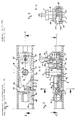
- a slide-shaped part 2 made of plastic is guided in a longitudinally displaceable manner, in which a two-armed locking lever 3 is pivotally mounted about a bolt 4 forming an axis.
- the bolt 4 has a thread-free shaft 6 below its hexagon head 5, to which a part 7 with a smaller diameter is provided with a thread to form an annular shoulder.
- the threaded part 7 is screwed into a threaded bore of the locking lever 3 so far that the ring shoulder is supported on one side of the locking lever 3.
- the deflection fitting for the shoulder strap freely rotatable.
- This deflection fitting consists of an essentially triangular part, which is provided below its bearing bore with a slot parallel to its base with rounded edges, through which the shoulder belt is guided and via which it runs to the seat belt retractor with automatic locking system, for example arranged in the floor area of the motor vehicle.
- the sled-shaped part 2 consists of a lower shell 9 and an upper shell 10, both of which are locked together.
- the two shells 9, 10 consist of plastic injection molded parts.
- the locking lever 3 is held between the two shell-shaped parts 9, 10.
- the lower shell-shaped part 9 is provided with a central recess 11 into which an annular bead 12 which surrounds the bore of the locking lever 3 engages.
- the recess 11 of the lower shell 9 is also surrounded by an annular bead 13, on the upper side of which the locking lever 3 is supported.
- the upper shell 10 of the sled-shaped part 9 is also provided with a bore in which a part of the thread-free shaft 6 of the screw bolt 4 is held.
- the bore is surrounded by an annular wall 14, the lower end of which is supported in the manner shown in FIG. 2 on the upper side of the locking lever 3.
- the locking lever 3 is provided with lateral parts 15, 16 in the form of circular sections, the circumferential surfaces of which are curved in the shape of an arc of a circle and are concentric with the screw bolt 4.
- the diameter of the circular disk-shaped part of the locking lever 3 formed by the two circular section-shaped parts 15, 16 corresponds approximately to the inner spacing of the lateral webs 18, 19 of the profile rail 1.
- the profile Rail 1 are provided with recesses 20 at regular intervals.
- a latching projection 21 can engage in these latching recesses 20 and is provided as a hook-shaped part on the left arm 22 of the latching lever 3 in FIG. 1.
- This hook-shaped latching projection 21 is acted upon by a compression spring 23 in the direction of the web 19, so that the hook-shaped part 21 can snap into the latching openings 20 and latch when it hits such an opening.
- the compression spring 23 is supported on the side of the lever arm 22 of the locking lever 3 opposite the latching projection 21 and is held in a corresponding recess 25 in the slide-shaped part 2.
- the other arm 26 of the locking lever 3 is provided on its upper side shown in FIG. 1 with a V-shaped groove 27.
- the lower arm 28 of a two-armed actuating lever 29 engages in this groove and is mounted in the upper shell part 10 of the sled-shaped part 9 so that it can pivot about an axis 30.
- the other arm 31 of the lever 29 is provided with an operating button 32. If the actuating lever 29 is pivoted about the axis 30, which is arranged transversely to the adjusting rail 1, in a plane parallel to the central plane of the adjusting rail 1, the lower end 33 of the lower arm 28 slides out of its central position shown in full lines in FIG.
- the locking lever 3 In this unlocked position, the locking lever 3 can be moved together with the sled-shaped part 9 in the longitudinal direction of the adjustment rail 1 to adjust the height of the deflection fitting.
- the web 18 of the adjustment rail 1 is provided with cutouts 40 which are arranged at the same distance as the latching recesses 20 in the other web 19.
- the rounded end part 41 of a resilient arm 42 which engages in one piece with the lower shell 9 snaps into these recesses 40 of the sled-shaped part 2 is formed.
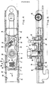
- FIGS. 4 and 5 essentially corresponds to the previously described first embodiment. Therefore, all reference numerals of identical or equivalent parts have been retained. In the following, only the corresponding differences of this embodiment compared to the first described embodiment are additionally explained.
- the locking lever 3 has essentially the shape described above.
- the locking projection 21 according to the embodiment according to FIGS. 4 and 5 has a steep slope in the locking direction (arrow direction a) and counter to the locking direction flat falling edge 58 is formed.
- the latching projection 21 can more easily engage in the corresponding latching openings 20.
- the corresponding edges of the locking openings are also designed in a special way.
- protruding edge portions 60 are formed in the interior of the rail 1, into which the steep flank 56 of the latch 21 can engage.
- convex shapes 62 are formed, which form a corresponding guide for the possibly passing locking projection 21 of the locking lever 3 such that it is moved in the direction of the locking opening 20.
- the spring force of a compression spring 66 which is accommodated in a chamber 68, which is composed of the troughs 70 and 72 of the upper and lower slide halves and a corresponding opening in the locking lever acts on the latching lever 3.
- the compression spring 66 is supported on one side on the upper and lower half of the slide and acts on the other side of the locking lever in the vertical direction with respect to the direction of advance of the slide (arrow a).
- a second nose 64 is formed, which can each engage in the cutouts 40.
- a projection 75 projecting laterally into the rail 1 is formed in such a way that it may abut the corner of the locking lever 3, which lies opposite the latching projection and thereby initiates a forced actuation of the locking lever .
- the projection 75 protruding into the rail also forms an additional safeguard for preventing the carriage 2 from being off the rail is pulled out.
- the actuating device consists of a two-armed actuating lever pivotally mounted in the sled-shaped part 2, one arm 28 of which engages in a triangular recess 50 of the locking lever.
- the actuating lever 29 In the rest position, the actuating lever 29 lies with its arm 28 in a corner region of the triangular recess 50, as can be seen in FIG. 4.
- the actuating lever 29 is secured by springs 52 and 54 resting on its lower arm 28.
- a bush 80 is molded, preferably injection molded.
- the bolt 4 is guided through this bushing, on which the deflection fitting (not shown in FIG. 5) sits.
- the rolled-up spring 45 is arranged with its rolled-up part stationary on the rail 1, as can be seen in FIGS. 4 and 5.
- two resilient arms 42 and 78 which are arranged symmetrically to one another, are formed, each snapping into opposite latching openings 20 or recesses 40 and thus producing a latching noise when the sled-shaped part 2 is moved along the rail 1.
- the locking lever 3 is shown with solid lines in its locking position.
- the dash-dotted lines correspond to the position of the locking lever 3 during the longitudinal displacement in the rail 1.
- a pivotable additional lever 82 is shown, which in its normal position in a corresponding recess of the Ver locking lever 3 is folded.
- the additional lever 82 is arranged in such a way that acceleration forces which may act in the direction of arrow a pivot it outward due to its inertia, as is indicated in the dashed lines.
- this additional lever hooks when this sled-shaped part 2 accelerates in the event of a crash into the next latching opening and exerts a torque on the locking lever 3 such that the latching projection 21 engages in a corresponding latching opening 20.
- FIGS. 6 and 7 show a further embodiment of the height-adjustable deflection fitting according to the invention.
- the actuating device for the locking lever 3 is formed by a rotary knob 80 which is seated on the hexagon head 5 of the bolt 4. By turning this knob appropriately, the locking lever 3 can be unlocked and the carriage can be moved longitudinally accordingly. The actuation of the locking lever 3 in the corresponding latching opening in turn causes the compression spring 66 after releasing the rotary knob 80.
- This embodiment also includes an additional lever 84, which is, however, subject to a different operating mechanism.
- the lever 84 is connected to the rotary knob 80 via a lever mechanism consisting of the levers 86 and 88 in such a way that it can be moved from an inactive position into a pivoted-out active position in accordance with the rotary movement of this rotary knob.
- the lever 84 In the actuating position of the rotary knob 80, which is shown in FIG. 6, the lever 84 is moved into the corresponding recess in the locking lever 3. In this position the Slides can therefore be easily moved lengthways. If, after a corresponding longitudinal displacement in the rail, the slide-shaped part is stopped, the lever 84 is extended, for example by the spring force of a spring, not shown.
Landscapes
- Engineering & Computer Science (AREA)
- Mechanical Engineering (AREA)
- Seats For Vehicles (AREA)
- Automotive Seat Belt Assembly (AREA)
Applications Claiming Priority (2)
| Application Number | Priority Date | Filing Date | Title |
|---|---|---|---|
| DE3844258A DE3844258A1 (de) | 1988-12-29 | 1988-12-29 | Hoehenverstellbarer umlenkbeschlag fuer sicherheitsgurte von kraftfahrzeugen |
| DE3844258 | 1988-12-29 |
Publications (2)
| Publication Number | Publication Date |
|---|---|
| EP0376320A1 true EP0376320A1 (fr) | 1990-07-04 |
| EP0376320B1 EP0376320B1 (fr) | 1993-09-22 |
Family
ID=6370479
Family Applications (1)
| Application Number | Title | Priority Date | Filing Date |
|---|---|---|---|
| EP89124091A Expired - Lifetime EP0376320B1 (fr) | 1988-12-29 | 1989-12-28 | Ferrure de renvoi, réglable en hauteur, pour ceintures de sécurité de véhicule |
Country Status (3)
| Country | Link |
|---|---|
| US (1) | US4989900A (fr) |
| EP (1) | EP0376320B1 (fr) |
| DE (2) | DE3844258A1 (fr) |
Cited By (6)
| Publication number | Priority date | Publication date | Assignee | Title |
|---|---|---|---|---|
| FR2664548A1 (fr) * | 1990-07-13 | 1992-01-17 | Autoliv Klippan Snc | Dispositif de reglage de position pour renvoi de sangle, et ceinture de securite ainsi equipee. |
| FR2664549A1 (fr) * | 1990-07-13 | 1992-01-17 | Autoliv Klippan Snc | Dispositif de reglage de position pour renvoi de sangle, et ceinture de securite ainsi equipee. |
| EP0636522A1 (fr) * | 1993-07-30 | 1995-02-01 | TRW Occupant Restraint Systems GmbH | Dispositif de réglage en hauteur d'une ferrure de ceinture de sécurité |
| DE4412672A1 (de) * | 1994-04-13 | 1995-10-19 | Autoliv Dev | Höhenverstellvorrichtung mit Zwangsverriegelung |
| WO1999006247A1 (fr) * | 1997-07-31 | 1999-02-11 | Albert Griesemer | Systeme d'ajustement en hauteur pour garnitures de renvoi de ceintures de securite de vehicules |
| DE102007058398A1 (de) | 2007-12-03 | 2009-06-04 | Key Plastics Lennestadt Gmbh & Co. Kg | Höhenversteller für einen Fahrzeugsicherheitsgurt |
Families Citing this family (19)
| Publication number | Priority date | Publication date | Assignee | Title |
|---|---|---|---|---|
| JPH0798470B2 (ja) * | 1990-08-30 | 1995-10-25 | 株式会社東海理化電機製作所 | オートマチツクシートベルト装置 |
| US5366243A (en) * | 1993-03-25 | 1994-11-22 | Trw Vehicle Safety Systems Inc. | Height adjuster for seat belt shoulder strap |
| DE4327820A1 (de) * | 1993-08-19 | 1995-02-23 | Autoliv Dev | Strammertauglicher höhenverstellbarer Umlenkbeschlag |
| DE19530663C2 (de) * | 1995-08-21 | 2001-05-03 | Inova Gmbh Tech Entwicklungen | Höhenversteller für einen Fahrzeugsicherheitsgurt |
| DE29606526U1 (de) * | 1996-04-10 | 1996-08-14 | Trw Occupant Restraint Systems Gmbh, 73551 Alfdorf | Gurthöhenversteller für ein Fahrzeug-Sicherheitsgurtsystem |
| DE29606521U1 (de) * | 1996-04-10 | 1996-08-08 | Trw Occupant Restraint Systems Gmbh, 73551 Alfdorf | Verstellvorrichtung für einen Umlenkbeschlag |
| US5911439A (en) * | 1996-04-19 | 1999-06-15 | Takata (Europe) Vehicle Safety Technology Gmbh | Vertical adjustment for the deflection fitting of a safety belt |
| EP0802094B1 (fr) * | 1996-04-19 | 2004-02-11 | TAKATA-PETRI (Ulm) GmbH | Réglage en hauteur d'un renvoi de ceinture de sécurité |
| US5924731A (en) * | 1998-06-22 | 1999-07-20 | Trw Vehicle Safety Systems Inc. | Height adjuster for seat belt webbing |
| US6186548B1 (en) * | 1999-02-04 | 2001-02-13 | Trw Vehicle Safety Systems Inc. | D-ring height adjuster |
| US7469928B2 (en) * | 2006-01-30 | 2008-12-30 | Autoliv Asp, Inc. | Adaptive seat belt system |
| DE102007032547B4 (de) * | 2007-07-12 | 2020-09-10 | Zf Automotive Germany Gmbh | Schlitten für einen Höhenversteller eines Sicherheitsgurtsystems |
| DE102011014175B4 (de) * | 2011-03-16 | 2021-05-12 | Autoliv Development Ab | Höhenversteller für einen Befestigungsbeschlag eines Sicherheitsgurt-Systems |
| CN102991560B (zh) * | 2011-09-08 | 2016-01-13 | 明门香港股份有限公司 | 婴儿车架及其小腿靠装置 |
| US8523229B1 (en) * | 2012-09-12 | 2013-09-03 | Autoliv Asp, Inc. | Seatbelt height adjuster assembly |
| US8991866B2 (en) | 2013-06-17 | 2015-03-31 | Nissan North America, Inc. | Vehicle pillar trim assembly |
| CN109624910B (zh) * | 2018-11-06 | 2020-08-18 | 宁波工程学院 | 一种侧锁式安全带高度调节器 |
| CN109624912B (zh) * | 2018-11-06 | 2020-06-05 | 宁波工程学院 | 一种具有保险功能的高度调节器 |
| US10981537B2 (en) * | 2019-06-07 | 2021-04-20 | Ford Global Technologies, Llc | Seatbelt height adjuster |
Citations (8)
| Publication number | Priority date | Publication date | Assignee | Title |
|---|---|---|---|---|
| EP0049572A1 (fr) * | 1980-10-08 | 1982-04-14 | Toyota Jidosha Kabushiki Kaisha | Dispositif d'ancrage pour une ceinture de siège |
| DE3151019A1 (de) * | 1981-12-23 | 1983-07-14 | Keiper Automobiltechnik Gmbh & Co Kg, 5630 Remscheid | Vorrichtung zum befestigen des oberen umlenkbeschlages fuer einen dreipunktsicherheitsgurt an der karosserie eines kraftfahrzeuges |
| DE8412788U1 (de) * | 1984-04-26 | 1984-09-27 | Autoliv GmbH, 2200 Elmshorn | Hoehenverstellbare befestigungs- oder umlenkvorrichtung fuer den sicherheitsgurt eines sicherheitssystems in kraftfahrzeugen |
| DE8322546U1 (de) * | 1983-08-04 | 1984-12-06 | TRW Repa GmbH, 7071 Alfdorf | Beschlag fuer einen sicherheitsgurt fuer kraftfahrzeuge |
| EP0182337A2 (fr) * | 1984-11-21 | 1986-05-28 | Autoliv Development Aktiebolag | Ancrage de ceinture de sécurité |
| DE3710894A1 (de) * | 1987-04-01 | 1988-10-20 | Daimler Benz Ag | Vorrichtung zur hoehenverstellung eines umlenkbeschlages eines fahrzeug-sicherheitsgurtes |
| DE3713137A1 (de) * | 1987-04-16 | 1988-11-03 | Trw Repa Gmbh | Sicherheitsgurt-rueckhaltesystem fuer fahrzeuginsassen |
| EP0290621A1 (fr) * | 1986-11-26 | 1988-11-17 | Takata Corporation | Systeme d'ancrage pour ceintures de securite |
Family Cites Families (9)
| Publication number | Priority date | Publication date | Assignee | Title |
|---|---|---|---|---|
| US3713137A (en) * | 1970-11-23 | 1973-01-23 | Harnischfeger Corp | Digital to analog converter |
| JPS5841977Y2 (ja) * | 1978-09-08 | 1983-09-22 | 三菱自動車工業株式会社 | シ−トベルト用リトラクタ装置 |
| DE3120182C2 (de) * | 1981-05-21 | 1984-08-16 | Ford-Werke AG, 5000 Köln | Kraftfahrzeug mit höhenverstellbarem Sicherheitsgurt-Umlenkbeschlag |
| JPS5822359U (ja) * | 1981-08-07 | 1983-02-12 | 日本精工株式会社 | 調節可能なシ−トベルト用アンカ−装置 |
| JPS5877761U (ja) * | 1981-11-24 | 1983-05-26 | 日本精工株式会社 | スル−アンカ−取付装置 |
| US4538832A (en) * | 1983-02-14 | 1985-09-03 | Ase (Uk) Limited | Adjustable seat belt anchorage |
| DE3406047A1 (de) * | 1983-08-04 | 1985-02-21 | TRW Repa GmbH, 7071 Alfdorf | Beschlag fuer einen sicherheitsgurt fuer kraftfahrzeuge |
| DE3514980A1 (de) * | 1984-05-28 | 1985-11-28 | TRW Repa GmbH, 7071 Alfdorf | Beschlag fuer einen sicherheitsgurt fuer kraftfahrzeuge |
| GB8611009D0 (en) * | 1986-05-06 | 1986-06-11 | Ase Uk Ltd | Adjustable anchorage |
-
1988
- 1988-12-29 DE DE3844258A patent/DE3844258A1/de active Granted
-
1989
- 1989-12-28 US US07/457,200 patent/US4989900A/en not_active Expired - Fee Related
- 1989-12-28 EP EP89124091A patent/EP0376320B1/fr not_active Expired - Lifetime
- 1989-12-28 DE DE89124091T patent/DE58905690D1/de not_active Expired - Fee Related
Patent Citations (8)
| Publication number | Priority date | Publication date | Assignee | Title |
|---|---|---|---|---|
| EP0049572A1 (fr) * | 1980-10-08 | 1982-04-14 | Toyota Jidosha Kabushiki Kaisha | Dispositif d'ancrage pour une ceinture de siège |
| DE3151019A1 (de) * | 1981-12-23 | 1983-07-14 | Keiper Automobiltechnik Gmbh & Co Kg, 5630 Remscheid | Vorrichtung zum befestigen des oberen umlenkbeschlages fuer einen dreipunktsicherheitsgurt an der karosserie eines kraftfahrzeuges |
| DE8322546U1 (de) * | 1983-08-04 | 1984-12-06 | TRW Repa GmbH, 7071 Alfdorf | Beschlag fuer einen sicherheitsgurt fuer kraftfahrzeuge |
| DE8412788U1 (de) * | 1984-04-26 | 1984-09-27 | Autoliv GmbH, 2200 Elmshorn | Hoehenverstellbare befestigungs- oder umlenkvorrichtung fuer den sicherheitsgurt eines sicherheitssystems in kraftfahrzeugen |
| EP0182337A2 (fr) * | 1984-11-21 | 1986-05-28 | Autoliv Development Aktiebolag | Ancrage de ceinture de sécurité |
| EP0290621A1 (fr) * | 1986-11-26 | 1988-11-17 | Takata Corporation | Systeme d'ancrage pour ceintures de securite |
| DE3710894A1 (de) * | 1987-04-01 | 1988-10-20 | Daimler Benz Ag | Vorrichtung zur hoehenverstellung eines umlenkbeschlages eines fahrzeug-sicherheitsgurtes |
| DE3713137A1 (de) * | 1987-04-16 | 1988-11-03 | Trw Repa Gmbh | Sicherheitsgurt-rueckhaltesystem fuer fahrzeuginsassen |
Cited By (11)
| Publication number | Priority date | Publication date | Assignee | Title |
|---|---|---|---|---|
| FR2664548A1 (fr) * | 1990-07-13 | 1992-01-17 | Autoliv Klippan Snc | Dispositif de reglage de position pour renvoi de sangle, et ceinture de securite ainsi equipee. |
| FR2664549A1 (fr) * | 1990-07-13 | 1992-01-17 | Autoliv Klippan Snc | Dispositif de reglage de position pour renvoi de sangle, et ceinture de securite ainsi equipee. |
| US5167428A (en) * | 1990-07-13 | 1992-12-01 | General Engineering (Netherlands) Bv | Position-adjustment device for a belt-guide, and safety-belt provided therewith |
| EP0636522A1 (fr) * | 1993-07-30 | 1995-02-01 | TRW Occupant Restraint Systems GmbH | Dispositif de réglage en hauteur d'une ferrure de ceinture de sécurité |
| US5460410A (en) * | 1993-07-30 | 1995-10-24 | Trw Repa Gmbh | Device for adjustably mounting a seat belt fitting to a vehicle bodywork |
| DE4412672A1 (de) * | 1994-04-13 | 1995-10-19 | Autoliv Dev | Höhenverstellvorrichtung mit Zwangsverriegelung |
| DE4412672C2 (de) * | 1994-04-13 | 1998-03-12 | Autoliv Dev | Höhenverstellvorrichtung mit Zwangsverriegelung |
| WO1999006247A1 (fr) * | 1997-07-31 | 1999-02-11 | Albert Griesemer | Systeme d'ajustement en hauteur pour garnitures de renvoi de ceintures de securite de vehicules |
| US6334629B1 (en) | 1997-07-31 | 2002-01-01 | Albert Griesemer | Height adjustment means for safety belt defector fittings of vehicles |
| DE102007058398A1 (de) | 2007-12-03 | 2009-06-04 | Key Plastics Lennestadt Gmbh & Co. Kg | Höhenversteller für einen Fahrzeugsicherheitsgurt |
| EP2067670A2 (fr) | 2007-12-03 | 2009-06-10 | Key Plastics Lennestadt GmbH & Co. KG | Réglage en hauteur pour une ceinture de sécurité de véhicule |
Also Published As
| Publication number | Publication date |
|---|---|
| DE58905690D1 (de) | 1993-10-28 |
| DE3844258C2 (fr) | 1993-04-08 |
| DE3844258A1 (de) | 1990-07-12 |
| US4989900A (en) | 1991-02-05 |
| EP0376320B1 (fr) | 1993-09-22 |
Similar Documents
| Publication | Publication Date | Title |
|---|---|---|
| EP0376320B1 (fr) | Ferrure de renvoi, réglable en hauteur, pour ceintures de sécurité de véhicule | |
| DE69120749T2 (de) | Verriegelungsvorrichtung zur Verwendung in einem Fahrzeug | |
| DE69700388T2 (de) | Fahrzeugsitzverriegelung und Sitz mit einem solchen Mechanismus | |
| DE3334510C2 (fr) | ||
| EP0158990B1 (fr) | Siège d'automobile | |
| DE10107237C5 (de) | Verstelleinrichtung für Kraftfahrzeugsitze | |
| DE4342400A1 (de) | Überrollbügeleinrichtung mit Innenführung und Außenführung | |
| DE4211566A1 (de) | Mit einer selbsttätigen Nachstelleinrichtung versehene Handbremse | |
| EP0636522B1 (fr) | Dispositif de réglage en hauteur d'une ferrure de ceinture de sécurité | |
| EP1107878B1 (fr) | Dispositif de fixation pour siege enfant | |
| DE4427011A1 (de) | Verschluß für Sicherheitsgurte | |
| DE3873468T2 (de) | Sicherheitsgurthaltevorrichtung mit manueller lageverstellung. | |
| DE3149518A1 (de) | Sicherheitsgurtsystem fuer kraftfahrzeuge | |
| DE3109302A1 (de) | Sicherheitsverriegelung an rueckenlehnen von fahrzeugsitzen | |
| DE19532530C1 (de) | Rücksitzanlage für ein Kraftfahrzeug, insbesondere Personenkraftwagen | |
| DE68905756T2 (de) | Handvorrichtung zur verstellung eines sicherheitsgurtels. | |
| DE3225862A1 (de) | Vorrichtung zur stufenweisen hoehenverstellung und befestigung des oberen umlenkbeschlages fuer einen sicherheitsgurt | |
| DE4102312C2 (de) | Sitzschiene für Fahrzeugsitze, insbesondere für Kraftfahrzeugsitze | |
| DE2525040A1 (de) | Kopfstuetze fuer fahrzeugsitze | |
| EP1477365B1 (fr) | Dispositif de fixation pour un coffre de toit | |
| DE10137645B4 (de) | Armlehne, insbesondere für Fahrzeuge | |
| DE2827409A1 (de) | Auf fahrzeugbeschleunigung ansprechende, justierbare sensorvorrichtung | |
| DE10013584B4 (de) | Halteeinrichtung für schwenkbewegliche Türen oder Klappen, vornehmlich zum Einsatz an Kraftfahrzeugen | |
| EP0359954A1 (fr) | Dispositif de régulation d'hauteur pour un anneau de renvoi d'un système de retenue à ceinture de sécurité dans des véhicules automobiles | |
| DE3813527A1 (de) | Vorrichtung zur hoehenverstellung eines verankerungsbeschlages fuer einen sicherheitsgurt |
Legal Events
| Date | Code | Title | Description |
|---|---|---|---|
| PUAI | Public reference made under article 153(3) epc to a published international application that has entered the european phase |
Free format text: ORIGINAL CODE: 0009012 |
|
| AK | Designated contracting states |
Kind code of ref document: A1 Designated state(s): DE ES FR GB IT SE |
|
| 17P | Request for examination filed |
Effective date: 19901213 |
|
| 17Q | First examination report despatched |
Effective date: 19910816 |
|
| RAP1 | Party data changed (applicant data changed or rights of an application transferred) |
Owner name: AUTOLIV-KOLB GMBH & CO. |
|
| GRAA | (expected) grant |
Free format text: ORIGINAL CODE: 0009210 |
|
| AK | Designated contracting states |
Kind code of ref document: B1 Designated state(s): DE ES FR GB IT SE |
|
| PG25 | Lapsed in a contracting state [announced via postgrant information from national office to epo] |
Ref country code: IT Free format text: LAPSE BECAUSE OF FAILURE TO SUBMIT A TRANSLATION OF THE DESCRIPTION OR TO PAY THE FEE WITHIN THE PRE;WARNING: LAPSES OF ITALIAN PATENTS WITH EFFECTIVE DATE BEFORE 2007 MAY HAVE OCCURRED AT ANY TIME BEFORE 2007. THE CORRECT EFFECTIVE DATE MAY BE DIFFERENT FROM THE ONE RECORDED.SCRIBED TIME-LIMIT Effective date: 19930922 Ref country code: SE Effective date: 19930922 Ref country code: ES Free format text: THE PATENT HAS BEEN ANNULLED BY A DECISION OF A NATIONAL AUTHORITY Effective date: 19930922 |
|
| REF | Corresponds to: |
Ref document number: 58905690 Country of ref document: DE Date of ref document: 19931028 |
|
| GBT | Gb: translation of ep patent filed (gb section 77(6)(a)/1977) |
Effective date: 19931012 |
|
| RAP2 | Party data changed (patent owner data changed or rights of a patent transferred) |
Owner name: AUTOLIV DEVELOPMENT AKTIEBOLAG |
|
| ET | Fr: translation filed | ||
| PLBE | No opposition filed within time limit |
Free format text: ORIGINAL CODE: 0009261 |
|
| STAA | Information on the status of an ep patent application or granted ep patent |
Free format text: STATUS: NO OPPOSITION FILED WITHIN TIME LIMIT |
|
| 26N | No opposition filed | ||
| PGFP | Annual fee paid to national office [announced via postgrant information from national office to epo] |
Ref country code: FR Payment date: 19981209 Year of fee payment: 10 |
|
| PGFP | Annual fee paid to national office [announced via postgrant information from national office to epo] |
Ref country code: GB Payment date: 19981231 Year of fee payment: 10 |
|
| PG25 | Lapsed in a contracting state [announced via postgrant information from national office to epo] |
Ref country code: GB Free format text: LAPSE BECAUSE OF NON-PAYMENT OF DUE FEES Effective date: 19991228 |
|
| GBPC | Gb: european patent ceased through non-payment of renewal fee |
Effective date: 19991228 |
|
| PG25 | Lapsed in a contracting state [announced via postgrant information from national office to epo] |
Ref country code: FR Free format text: LAPSE BECAUSE OF NON-PAYMENT OF DUE FEES Effective date: 20000831 |
|
| REG | Reference to a national code |
Ref country code: FR Ref legal event code: ST |
|
| PGFP | Annual fee paid to national office [announced via postgrant information from national office to epo] |
Ref country code: DE Payment date: 20040108 Year of fee payment: 15 |
|
| PG25 | Lapsed in a contracting state [announced via postgrant information from national office to epo] |
Ref country code: DE Free format text: LAPSE BECAUSE OF NON-PAYMENT OF DUE FEES Effective date: 20050701 |