EP0376452A2 - Véhicule ferroviaire - Google Patents
Véhicule ferroviaire Download PDFInfo
- Publication number
- EP0376452A2 EP0376452A2 EP89311549A EP89311549A EP0376452A2 EP 0376452 A2 EP0376452 A2 EP 0376452A2 EP 89311549 A EP89311549 A EP 89311549A EP 89311549 A EP89311549 A EP 89311549A EP 0376452 A2 EP0376452 A2 EP 0376452A2
- Authority
- EP
- European Patent Office
- Prior art keywords
- vehicle
- vehicle body
- pair
- prime mover
- railroad
- Prior art date
- Legal status (The legal status is an assumption and is not a legal conclusion. Google has not performed a legal analysis and makes no representation as to the accuracy of the status listed.)
- Granted
Links
Images

Classifications
-
- B—PERFORMING OPERATIONS; TRANSPORTING
- B61—RAILWAYS
- B61F—RAIL VEHICLE SUSPENSIONS, e.g. UNDERFRAMES, BOGIES OR ARRANGEMENTS OF WHEEL AXLES; RAIL VEHICLES FOR USE ON TRACKS OF DIFFERENT WIDTH; PREVENTING DERAILING OF RAIL VEHICLES; WHEEL GUARDS, OBSTRUCTION REMOVERS OR THE LIKE FOR RAIL VEHICLES
- B61F5/00—Constructional details of bogies; Connections between bogies and vehicle underframes; Arrangements or devices for adjusting or allowing self-adjustment of wheel axles or bogies when rounding curves
- B61F5/38—Arrangements or devices for adjusting or allowing self- adjustment of wheel axles or bogies when rounding curves, e.g. sliding axles, swinging axles
-
- B—PERFORMING OPERATIONS; TRANSPORTING
- B61—RAILWAYS
- B61C—LOCOMOTIVES; MOTOR RAILCARS
- B61C9/00—Locomotives or motor railcars characterised by the type of transmission system used; Transmission systems specially adapted for locomotives or motor railcars
- B61C9/38—Transmission systems in or for locomotives or motor railcars with electric motor propulsion
- B61C9/52—Transmission systems in or for locomotives or motor railcars with electric motor propulsion with transmission shafts at an angle to the driving axles
-
- B—PERFORMING OPERATIONS; TRANSPORTING
- B61—RAILWAYS
- B61F—RAIL VEHICLE SUSPENSIONS, e.g. UNDERFRAMES, BOGIES OR ARRANGEMENTS OF WHEEL AXLES; RAIL VEHICLES FOR USE ON TRACKS OF DIFFERENT WIDTH; PREVENTING DERAILING OF RAIL VEHICLES; WHEEL GUARDS, OBSTRUCTION REMOVERS OR THE LIKE FOR RAIL VEHICLES
- B61F5/00—Constructional details of bogies; Connections between bogies and vehicle underframes; Arrangements or devices for adjusting or allowing self-adjustment of wheel axles or bogies when rounding curves
- B61F5/02—Arrangements permitting limited transverse relative movements between vehicle underframe or bolster and bogie; Connections between underframes and bogies
- B61F5/22—Guiding of the vehicle underframes with respect to the bogies
-
- F—MECHANICAL ENGINEERING; LIGHTING; HEATING; WEAPONS; BLASTING
- F02—COMBUSTION ENGINES; HOT-GAS OR COMBUSTION-PRODUCT ENGINE PLANTS
- F02B—INTERNAL-COMBUSTION PISTON ENGINES; COMBUSTION ENGINES IN GENERAL
- F02B3/00—Engines characterised by air compression and subsequent fuel addition
- F02B3/06—Engines characterised by air compression and subsequent fuel addition with compression ignition
Definitions
- This invention relates to a railroad vehicle and, more particularly, to a railroad vehicle in which motive power is transmitted by a right angle cardan system, and the body of which is inclined by a natural pendulum system.
- a vehicle body inclining system is known based on a natural pendulum system in which the vehicle body is inclined by the centrifugal force to provide a natural balance.
- a parallel cardan system in which the main motor is incorporated in a truck is adopted as a power transmission system.
- the vehicle body is not forcibly inclined by the reaction torque of the driving torque of the main motor.
- the axis of the output shaft of the diesel engine extends in the longitudinal direction of the vehicle.
- the vehicle body is therefore forcibly inclined by the reaction torque of the driving torque produced by the diesel engine. For this reason, no vehicle based on the right angle cardan system has been designed in which the vehicle body is inclined by a natural pendulum system.
- a 391-type natural pendulum railcar for three-unit trains was made on an experimental basis using a gas turbine engine.
- front and rear units connected to a central motive power unit were of pendulum type, but the motive power unit in which the gas turbine was mounted was designed as a non-pendulum type.
- a railroad vehicle comprising a vehicle body inclined by a natural pendulum system, a pair of trucks respectively disposed at longitudinally opposed ends of said vehicle, each said truck having an axle and a pair of drive wheels, and each said pair of drive wheels being driven by a respective output shaft from a prime mover disposed in the vicinity of the centre of said vehicle, said output shafts extending longitudinally of said vehicle and being caused to rotate with equal output torques in opposite directions, whereby reaction torques produced in response to said output torques are cancelled and the possibility of any forced inclination of the vehicle body due to such reaction torques is substantially eliminated.
- a vehicle construction whereby, even in the case of a railcar having a prime mover disposed on the vehicle body side and having a power transmission system based on the right angle cardan system, the vehicle body can be inclined by a natural pendulum system while eliminating the possibility of the vehicle body being forcibly inclined at the time of transmission of the power of the prime mover, thereby enabling development of a high-speed vehicle or rail car.
- a pair of prime movers having the same performance are mounted on the vehicle body in the vicinity of the centre thereof so as to face in the opposite directions with their respective output shafts facing respective axles and drive wheels.
- a single prime mover may be provided having a pair of output shafts disposed at its opposite ends, the prime mover being mounted on the vehicle body in the vicinity of the centre thereof.
- each propeller shaft includes an expansion section formed from mutually engaging splined portions. It is particularly preferred that these splined portion be provided with friction reducing means such as ball bearings or a coating of low friction material. This limits the likelihood of any friction induced forces that may undesirably incline the vehicle body.
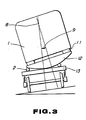
- Figs. 1 to 3 show a natural pendulum railroad vehicle based on a right angle cardan system which vehicle represents a first embodiment of the present invention
- Figs. 1 to 3 are diagrams of the basic construction of a natural pendulum railroad vehicle based on a right angle cardan system.
- the railroad vehicle of this embodiment comprises a two-shaft bogie and has a two-prime-mover system in which a pair of trucks has power shafts disposed coaxially with each other on their inner sides alone.
- a vehicle body 1 is provided with pendulum beams 12 with bolster springs 11 interposed between the vehicle body 1 and the pendulum beams 12.
- Pendulum rollers 2 are disposed on trucks 13, and the pendulum beams 12 are supported on the pendulum rollers 2, thereby enabling the vehicle body to be inclined about the centre 8 of pendulum rotation.
- a reference character 9 denotes the vehicle inclination angle.
- a pair of prime movers 4 are mounted to a bottom portion of the vehicle body 1 in the vicinity of the centre thereof, and each prime mover 4 has an output shaft 4S extending in the longitudinal direction of the vehicle body.
- the prime mover 4 is an internal combustion engine, but it may be an electric motor, or any type of engine.
- the pair of prime movers 4 having substantially the same outputs and having the same performance, are opposedly disposed in the vicinity of the centre of the vehicle and are controlled to produce equal power outputs at all times.
- the output shafts 4S are connected to propeller shafts 3 to rotate the shafts 3 in a rotational direction 5 and a direction 6 opposite to the direction 5, respectively.
- each prime mover 4 is transmitted from the output shaft 4S to an axle 10 via propeller shaft 3 and a speed reducer 7.
- the axle 10 carries a pair of driving wheels 15.
- the speed reducers 7 include bevel gears disposed on the axles and engaging bevel gears operatively connected to the propeller shafts.
- the bevel gears are so arranged that both pairs of drive wheels rotate in the same direction to move the vehicle in one direction, e.g., the direction of the arrow D, when the propeller shafts 3 are rotated in the directions 5 and 6 opposite to each other.
- the gears on axles 10 face in the same direction as each other, whereas the propeller shaft gears face in opposite directions.
- two prime movers 4 having the same performance are provided on one vehicle, and the propeller shafts 3 are respectively rotated by the prime movers 4 in the opposite directions, thereby cancelling reaction torques produced when the prime movers 4 rotate with equal powers.
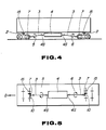
- FIGs. 4 and 5 The embodiment shown in Figs. 4 and 5 is based on a single prime mover system.
- a prime mover 4 disposed generally at the centre of the vehicle has a pair of output shafts 4S extending toward the front and rear ends of the vehicle, respectively.
- the output shafts 4S are connected to propeller shafts 3 to rotate the propeller shafts 3 in a rotational direction 5 and a direction 6 opposite to the direction 5, respectively.
- the power is transmitted from each output shaft 4S to an axle 10 via propeller shaft 3 and speed reducer 7.
- the axle 10 carries a pair of driving wheels 15.
- one prime mover 4 having a pair of output shafts disposed at its opposite ends is mounted to the vehicle body 1 generally at the centre thereof, and the power is transmitted from output shafts 4S to axles 10 disposed at the front and rear ends of the vehicle through respective propeller shafts 3.
- the propeller shafts 3 are rotated by the one prime mover 4 in the opposite directions, thereby cancelling reaction torques produced when the output shafts 4 rotate with equal powers.
- the vehicle body 1 is forcibly inclined by any reaction torque. In consequence, the vehicle body can be smoothly inclined by the natural pendulum effect.
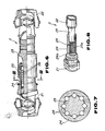
- a propeller shaft 3 has, as shown in Figs. 6 and 7, stationary yokes 21 and 22, a spline shaft yoke 23, and a sleeve yoke 24 having an inner splined portion.
- An expansion section 25 is formed by the spline-fitting the slide shaft yoke 23 within the sleeve yoke 24 and interposing ball bearings 26 between spline portions of the yokes 23 and 24.
- the ball bearings 26 enable a reduction in the frictional resistance caused when the expansion section 25 extends or contracts.
- a propeller shaft 3 in accordance with this embodiment has, as in the case of the arrangement shown in Fig. 6, stationary yokes 21 and 22, a spline shaft yoke 23, and a sleeve yoke 24 having a spline.
- An expansion section 25 is formed by spline-fitting the slide shaft yoke 23 and the yoke 24 with the spline sleeve.
- the frictional resistance between the two yokes during sliding is reduced, thereby enabling the vehicle body to effect a natural pendulum motion under a low-resistance condition.
- the present invention enables, for railroad vehicles such as railcars, a pendulum vehicle construction utilizing a natural pendulum action to make passengers feel more comfortable during travelling along a curve at a high speed even in the case of a vehicle having a prime mover such as an internal combustion engine mounted on the vehicle transmission mechanism.
- the present invention therefore enables an increase in the curve passage speed of vehicles having this type of power transmission mechanism.
- the frictional coefficients of spline portions of the propeller shaft connecting the prime mover and the driving wheel can be reduced, thereby enabling a reduction in the slide resistance at the time of expansion/contraction of the propeller shaft and removing a force resulting from the slide resistance which impedes the pendulum action.
Landscapes
- Engineering & Computer Science (AREA)
- Mechanical Engineering (AREA)
- Chemical & Material Sciences (AREA)
- Combustion & Propulsion (AREA)
- Transportation (AREA)
- Arrangement Or Mounting Of Propulsion Units For Vehicles (AREA)
- Motor Power Transmission Devices (AREA)
- Electric Propulsion And Braking For Vehicles (AREA)
- Connection Of Motors, Electrical Generators, Mechanical Devices, And The Like (AREA)
Applications Claiming Priority (4)
| Application Number | Priority Date | Filing Date | Title |
|---|---|---|---|
| JP63330974A JPH0629022B2 (ja) | 1988-12-29 | 1988-12-29 | 車体に原動機を取付けた直角カルダン方式による動力伝達機構を装備した自然振子式鉄道車両 |
| JP330974/88 | 1988-12-29 | ||
| JP1122982A JPH02304218A (ja) | 1989-05-18 | 1989-05-18 | 振子式気動車の推進軸 |
| JP122982/89 | 1989-05-18 |
Publications (3)
| Publication Number | Publication Date |
|---|---|
| EP0376452A2 true EP0376452A2 (fr) | 1990-07-04 |
| EP0376452A3 EP0376452A3 (fr) | 1991-03-13 |
| EP0376452B1 EP0376452B1 (fr) | 1994-05-04 |
Family
ID=26460006
Family Applications (1)
| Application Number | Title | Priority Date | Filing Date |
|---|---|---|---|
| EP89311549A Expired - Lifetime EP0376452B1 (fr) | 1988-12-29 | 1989-11-08 | Véhicule ferroviaire |
Country Status (5)
| Country | Link |
|---|---|
| EP (1) | EP0376452B1 (fr) |
| KR (1) | KR950014363B1 (fr) |
| CA (1) | CA2002947C (fr) |
| DE (1) | DE68915138T2 (fr) |
| ES (1) | ES2056228T3 (fr) |
Cited By (3)
| Publication number | Priority date | Publication date | Assignee | Title |
|---|---|---|---|---|
| CN112549934A (zh) * | 2020-12-04 | 2021-03-26 | 中车南京浦镇车辆有限公司 | 胶轮列车 |
| CN112849170A (zh) * | 2021-02-19 | 2021-05-28 | 安徽万航轨道交通装备有限公司 | 一种铁路机车火车头油电混合驱动装置 |
| IT202000013867A1 (it) * | 2020-06-10 | 2021-12-10 | Giuseppe Milazzo | Carrozza ferroviaria motrice comprendente uno o piu' carrelli alleggeriti |
Families Citing this family (1)
| Publication number | Priority date | Publication date | Assignee | Title |
|---|---|---|---|---|
| KR102741939B1 (ko) | 2022-06-20 | 2024-12-11 | 이당훈 | 내연기관의 연소촉진을 위한 흡기구 측 연소촉매 공급방법 및 그 시스템 |
Family Cites Families (6)
| Publication number | Priority date | Publication date | Assignee | Title |
|---|---|---|---|---|
| BE380497A (fr) * | ||||
| US2391103A (en) * | 1943-02-12 | 1945-12-18 | Transit Res Corp | Motor with separate drive shafts |
| FR1025447A (fr) * | 1949-11-18 | 1953-04-15 | Henschel & Sohn Gmbh | Installation de moteurs pour véhicules sur route et sur rail |
| FR1231813A (fr) * | 1959-04-16 | 1960-10-03 | Alsthom Cgee | Liaison entre bogie et caisse |
| DE2258645A1 (de) * | 1972-11-30 | 1974-06-20 | Orenstein & Koppel Ag | Elektromotoren zum gleichzeitigen antrieb von zwei in einem eisenbahn-drehgestell gelagerten achsen |
| DK373786A (da) * | 1986-08-06 | 1988-02-07 | Ascan As | Jernbanevogn med koerebogier |
-
1989
- 1989-09-21 KR KR1019890013597A patent/KR950014363B1/ko not_active Expired - Fee Related
- 1989-11-08 EP EP89311549A patent/EP0376452B1/fr not_active Expired - Lifetime
- 1989-11-08 DE DE68915138T patent/DE68915138T2/de not_active Expired - Fee Related
- 1989-11-08 ES ES89311549T patent/ES2056228T3/es not_active Expired - Lifetime
- 1989-11-14 CA CA002002947A patent/CA2002947C/fr not_active Expired - Lifetime
Cited By (4)
| Publication number | Priority date | Publication date | Assignee | Title |
|---|---|---|---|---|
| IT202000013867A1 (it) * | 2020-06-10 | 2021-12-10 | Giuseppe Milazzo | Carrozza ferroviaria motrice comprendente uno o piu' carrelli alleggeriti |
| CN112549934A (zh) * | 2020-12-04 | 2021-03-26 | 中车南京浦镇车辆有限公司 | 胶轮列车 |
| CN112849170A (zh) * | 2021-02-19 | 2021-05-28 | 安徽万航轨道交通装备有限公司 | 一种铁路机车火车头油电混合驱动装置 |
| CN112849170B (zh) * | 2021-02-19 | 2024-01-05 | 安徽万航轨道交通装备有限公司 | 一种铁路机车火车头油电混合驱动装置 |
Also Published As
| Publication number | Publication date |
|---|---|
| CA2002947C (fr) | 1995-04-25 |
| KR950014363B1 (ko) | 1995-11-25 |
| DE68915138D1 (de) | 1994-06-09 |
| DE68915138T2 (de) | 1994-08-18 |
| KR900009372A (ko) | 1990-07-04 |
| EP0376452B1 (fr) | 1994-05-04 |
| ES2056228T3 (es) | 1994-10-01 |
| EP0376452A3 (fr) | 1991-03-13 |
Similar Documents
| Publication | Publication Date | Title |
|---|---|---|
| EP1379424B9 (fr) | Configuration d'entrainement d'un vehicule a direction differentielle | |
| US6953408B2 (en) | Electric drive configuration for a skid steered vehicle | |
| AU2002249414A1 (en) | Drive configuration for a skid steered vehicle | |
| EP0376452B1 (fr) | Véhicule ferroviaire | |
| US4981193A (en) | Engine and transmission arrangement for four wheel drive vehicle | |
| JPS5830878A (ja) | 車輛 | |
| US5575217A (en) | Wheel set for a vehicle travelling on a guide path | |
| US4947761A (en) | Stub axle truck | |
| US4883000A (en) | Stub axle truck | |
| RU2243914C2 (ru) | Групповой электрический привод трехосной тележки тепловоза | |
| US775765A (en) | Vehicle-train. | |
| RU241666U1 (ru) | Тяговый привод локомотива | |
| SU1500536A1 (ru) | Моторна трехосна тележка | |
| JPH0629022B2 (ja) | 車体に原動機を取付けた直角カルダン方式による動力伝達機構を装備した自然振子式鉄道車両 | |
| RU2090403C1 (ru) | Экипаж рельсового транспортного средства | |
| JP2000062482A (ja) | ホイールクレーン | |
| JP3394056B2 (ja) | 鉄道車両用台車 | |
| US3734029A (en) | Resilient railway vehicle transmission | |
| SU1724497A1 (ru) | Тележка железнодорожного транспортного средства | |
| JPH0112985Y2 (fr) | ||
| JPH0487836A (ja) | 自動車の駆動力伝達機構 | |
| RU2232090C2 (ru) | Групповой привод двухосной тележки тепловоза | |
| JPH02304218A (ja) | 振子式気動車の推進軸 | |
| JP3351609B2 (ja) | 連接台車編成の制御方法 | |
| JPS63284029A (ja) | 四輪駆動機構 |
Legal Events
| Date | Code | Title | Description |
|---|---|---|---|
| PUAI | Public reference made under article 153(3) epc to a published international application that has entered the european phase |
Free format text: ORIGINAL CODE: 0009012 |
|
| AK | Designated contracting states |
Kind code of ref document: A2 Designated state(s): DE ES FR GB IT SE |
|
| PUAL | Search report despatched |
Free format text: ORIGINAL CODE: 0009013 |
|
| AK | Designated contracting states |
Kind code of ref document: A3 Designated state(s): DE ES FR GB IT SE |
|
| 17P | Request for examination filed |
Effective date: 19910521 |
|
| 17Q | First examination report despatched |
Effective date: 19921116 |
|
| GRAA | (expected) grant |
Free format text: ORIGINAL CODE: 0009210 |
|
| STAA | Information on the status of an ep patent application or granted ep patent |
Free format text: STATUS: THE PATENT HAS BEEN GRANTED |
|
| RAP1 | Party data changed (applicant data changed or rights of an application transferred) |
Owner name: FUJI JUKOGYO KABUSHIKI KAISHA Owner name: SHIKOKU RAILWAY COMPANY Owner name: RAILWAY TECHNICAL RESEARCH INSTITUTE |
|
| ITF | It: translation for a ep patent filed | ||
| AK | Designated contracting states |
Kind code of ref document: B1 Designated state(s): DE ES FR GB IT SE |
|
| REF | Corresponds to: |
Ref document number: 68915138 Country of ref document: DE Date of ref document: 19940609 |
|
| ET | Fr: translation filed | ||
| REG | Reference to a national code |
Ref country code: ES Ref legal event code: FG2A Ref document number: 2056228 Country of ref document: ES Kind code of ref document: T3 |
|
| EAL | Se: european patent in force in sweden |
Ref document number: 89311549.3 |
|
| PLBI | Opposition filed |
Free format text: ORIGINAL CODE: 0009260 |
|
| 26 | Opposition filed |
Opponent name: FIAT FERROVIARIA S.P.A. Effective date: 19950301 |
|
| REG | Reference to a national code |
Ref country code: GB Ref legal event code: IF02 |
|
| PGFP | Annual fee paid to national office [announced via postgrant information from national office to epo] |
Ref country code: ES Payment date: 20071106 Year of fee payment: 19 Ref country code: DE Payment date: 20071127 Year of fee payment: 19 |
|
| PGFP | Annual fee paid to national office [announced via postgrant information from national office to epo] |
Ref country code: IT Payment date: 20071127 Year of fee payment: 19 |
|
| PGFP | Annual fee paid to national office [announced via postgrant information from national office to epo] |
Ref country code: SE Payment date: 20071113 Year of fee payment: 19 |
|
| PGFP | Annual fee paid to national office [announced via postgrant information from national office to epo] |
Ref country code: GB Payment date: 20071029 Year of fee payment: 19 Ref country code: FR Payment date: 20071031 Year of fee payment: 19 |
|
| EUG | Se: european patent has lapsed | ||
| GBPC | Gb: european patent ceased through non-payment of renewal fee |
Effective date: 20081108 |
|
| PG25 | Lapsed in a contracting state [announced via postgrant information from national office to epo] |
Ref country code: IT Free format text: LAPSE BECAUSE OF NON-PAYMENT OF DUE FEES Effective date: 20081108 |
|
| REG | Reference to a national code |
Ref country code: FR Ref legal event code: ST Effective date: 20090731 |
|
| PG25 | Lapsed in a contracting state [announced via postgrant information from national office to epo] |
Ref country code: DE Free format text: LAPSE BECAUSE OF NON-PAYMENT OF DUE FEES Effective date: 20090603 |
|
| PG25 | Lapsed in a contracting state [announced via postgrant information from national office to epo] |
Ref country code: GB Free format text: LAPSE BECAUSE OF NON-PAYMENT OF DUE FEES Effective date: 20081108 |
|
| REG | Reference to a national code |
Ref country code: ES Ref legal event code: FD2A Effective date: 20081110 |
|
| PG25 | Lapsed in a contracting state [announced via postgrant information from national office to epo] |
Ref country code: ES Free format text: LAPSE BECAUSE OF NON-PAYMENT OF DUE FEES Effective date: 20081110 |
|
| PG25 | Lapsed in a contracting state [announced via postgrant information from national office to epo] |
Ref country code: SE Free format text: LAPSE BECAUSE OF NON-PAYMENT OF DUE FEES Effective date: 20081109 |
|
| PG25 | Lapsed in a contracting state [announced via postgrant information from national office to epo] |
Ref country code: FR Free format text: LAPSE BECAUSE OF NON-PAYMENT OF DUE FEES Effective date: 20081130 |
|
| RAP2 | Party data changed (patent owner data changed or rights of a patent transferred) |
Owner name: SHIKOKU RAILWAY COMPANY Owner name: RAILWAY TECHNICAL RESEARCH INSTITUTE Owner name: FUJI JUKOGYO KABUSHIKI KAISHA |
|
| RAP2 | Party data changed (patent owner data changed or rights of a patent transferred) |
Owner name: SHIKOKU RAILWAY COMPANY Owner name: RAILWAY TECHNICAL RESEARCH INSTITUTE Owner name: SUBARU CORPORATION |
|
| RIC2 | Information provided on ipc code assigned after grant |
Ipc: B61C 9/52 20060101ALI19930624BHEP Ipc: B61F 5/22 20060101ALI19930624BHEP Ipc: B61C 9/26 20060101AFI19930624BHEP |
|
| PLAB | Opposition data, opponent's data or that of the opponent's representative modified |
Free format text: ORIGINAL CODE: 0009299OPPO |
|
| R26D | Opposition deemed not to have been filed (corrected) |
Opponent name: FIAT FERROVIARIA S.P.A. Effective date: 19950704 |