EP0376512A2 - Système de direction pour véhicule - Google Patents
Système de direction pour véhicule Download PDFInfo
- Publication number
- EP0376512A2 EP0376512A2 EP89312656A EP89312656A EP0376512A2 EP 0376512 A2 EP0376512 A2 EP 0376512A2 EP 89312656 A EP89312656 A EP 89312656A EP 89312656 A EP89312656 A EP 89312656A EP 0376512 A2 EP0376512 A2 EP 0376512A2
- Authority
- EP
- European Patent Office
- Prior art keywords
- steering
- steering gear
- sensor means
- vehicle
- centre
- Prior art date
- Legal status (The legal status is an assumption and is not a legal conclusion. Google has not performed a legal analysis and makes no representation as to the accuracy of the status listed.)
- Withdrawn
Links
Images


Classifications
-
- B—PERFORMING OPERATIONS; TRANSPORTING
- B62—LAND VEHICLES FOR TRAVELLING OTHERWISE THAN ON RAILS
- B62D—MOTOR VEHICLES; TRAILERS
- B62D7/00—Steering linkage; Stub axles or their mountings
- B62D7/06—Steering linkage; Stub axles or their mountings for individually-pivoted wheels, e.g. on king-pins
- B62D7/14—Steering linkage; Stub axles or their mountings for individually-pivoted wheels, e.g. on king-pins the pivotal axes being situated in more than one plane transverse to the longitudinal centre line of the vehicle, e.g. all-wheel steering
- B62D7/15—Steering linkage; Stub axles or their mountings for individually-pivoted wheels, e.g. on king-pins the pivotal axes being situated in more than one plane transverse to the longitudinal centre line of the vehicle, e.g. all-wheel steering characterised by means varying the ratio between the steering angles of the steered wheels
- B62D7/1581—Steering linkage; Stub axles or their mountings for individually-pivoted wheels, e.g. on king-pins the pivotal axes being situated in more than one plane transverse to the longitudinal centre line of the vehicle, e.g. all-wheel steering characterised by means varying the ratio between the steering angles of the steered wheels characterised by comprising an electrical interconnecting system between the steering control means of the different axles
-
- B—PERFORMING OPERATIONS; TRANSPORTING
- B62—LAND VEHICLES FOR TRAVELLING OTHERWISE THAN ON RAILS
- B62D—MOTOR VEHICLES; TRAILERS
- B62D7/00—Steering linkage; Stub axles or their mountings
- B62D7/06—Steering linkage; Stub axles or their mountings for individually-pivoted wheels, e.g. on king-pins
- B62D7/14—Steering linkage; Stub axles or their mountings for individually-pivoted wheels, e.g. on king-pins the pivotal axes being situated in more than one plane transverse to the longitudinal centre line of the vehicle, e.g. all-wheel steering
- B62D7/15—Steering linkage; Stub axles or their mountings for individually-pivoted wheels, e.g. on king-pins the pivotal axes being situated in more than one plane transverse to the longitudinal centre line of the vehicle, e.g. all-wheel steering characterised by means varying the ratio between the steering angles of the steered wheels
- B62D7/159—Steering linkage; Stub axles or their mountings for individually-pivoted wheels, e.g. on king-pins the pivotal axes being situated in more than one plane transverse to the longitudinal centre line of the vehicle, e.g. all-wheel steering characterised by means varying the ratio between the steering angles of the steered wheels characterised by computing methods or stabilisation processes or systems, e.g. responding to yaw rate, lateral wind, load, road condition
Definitions
- This invention relates to a steering system for a vehicle having steerable roadwheels located on multiple axles.
- the system control module have the capability of precisely tracking the operational position of each of the steering gears mounted upon the vehicle. If only a single sensor is employed at each of the steering gears, it is possible that steering control could be adversely affected if the sensor's output were to drift out of adjustment. Failure of either sensor could also adversely affect operation of the system. Were either of these conditions to occur, operation of the system will be seriously impaired because the control module will not know the precise angle or position at which one or even both of the steering gears is being operated. As a result, the driver of the vehicle could be faced with a difficult task while attempting to control the vehicle.
- the steering system embodying the invention further comprises means responsive to the front and rear centre signals for calibrating the third and fourth sensor means by recording the value of the front steering position signal when the front centre signal is present and by recording the value of the rear steering position signal when the rear centre signal is present.
- the calibration means may further comprise means for determining a mean value for each of the recorded front and rear steering position signals. Thereafter, the front and rear steering position signals may be determined by comparing the instantaneous value of the position signal generated by each of the third and fourth sensor means with recorded mean values corresponding to each of said signals.
- the control means may further comprise means for comparing the calculated mean values of each of the recorded front and rear steering position signals with respective pairs of threshold values and means for generating a warning signal in the event that either or both of the calculated mean steering signal values lies outside of the appropriate threshold value ranges.
- the system may further comprise means responsive to such a warning signal for disabling the operation of the rear steering gear.
- a system embodying the present invention may be utilised in conjunction with a front steering gear comprising a slidable element mounted within a housing and coupled to the front roadwheels of the vehicle so as to provide steering force to the roadwheels, with the first sensor means comprising a detector for signalling whenever the sliding element is in the centre of its travel.
- the rear steering gear may comprise a slidable element mounted within a housing and coupled to the rear roadwheels of the vehicle so as to provide steering force to the roadwheels, and with the second sensor means comprising a detector for signalling whenever the slidable element located within the rear steering gears is in the centre of its travel.
- the third and fourth sensor means may comprise detectors for sensing the position of the slidable elements in the front and rear steering gears respectively, at any point along the sliding element's travel paths.
- Another aspect of the present invention involves a method for operating a steering system for a vehicle comprising the steps of sensing the centre position of a first steering gear associated with the front wheels of the vehicle by a first steering position sensor means; recording the value of a signal generated by a second steering position sensor means associated with the first steering gear upon sensing of the centre position by the first sensor means; sensing the centre position of a second steering gear, associated with the rear wheels of the vehicle, by a third steering position sensor means; recording the value of a signal generated by a fourth steering position sensor means associated with the second steering gear upon sensing of the centre position by a third sensor means, and comparing values derived by the recorded signal values from the second and fourth sensor means with the instantaneous outputs of the second and fourth sensor means to determine the instantaneous steering positions of the first and second steering gears, respectively.
- the instantaneous outputs of the second and fourth sensor means may be compared with corresponding calculated mean values of the recorded signals from the second and fourth steering position sensors.
- a vehicle, 8, equipped with the present invention has front and rear steerable roadwheels 14 and 16, respectively.
- a system according to the present invention could be applied to vehicles having steerable roadwheels on more than two axles.
- a system according to the present invention includes, inter alia , front steering gear 10 and rear steering gear 12, which steer the front and rear roadwheels 14 and 16, respectively.
- Front on-centre sensor 18 is included in the front steering gear, while rear on-centre sensor, 20 is included in the rear steering gear. Details of such sensors will be shown in the discussion of Figure 2 of this specification.
- the front and rear steering gears further include front travel path sensor 22 and rear travel path sensor 24, respectively. Because the travel path sensors are used for the purpose of detecting the position of the steering racks whenever the racks are not centred, the travel path sensors are labelled in Figure 3 as "off-centre position" sensors. Each of the sensors communicates with control module 26. The arrangement of the sensors and the control module are shown in Figure 3.
- the control module comprising a microprocessor including a ROM in which is stored various constants and control programs for operating the steering system of the present invention, as well as a CPU for reading out control programs for the ROM so as to execute recorded operations and a RAM which temporarily stores various data related to the operations to be executed within the CPU.
- the microprocessor further includes various input-output devices for controlling various input and output signals to and from the microprocessor.
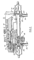
- FIG. 2 shows details of rear steering gear 12, it being understood that the sensor system shown in the rear steering gear is replicated in the front steering gear.
- the steering gear is noted to be electronically controlled and driven by motor 38, having stator windings 40 and armature 42.
- front steering gear 10 is manually operable.
- the present system is compatible with both power assisted and non-power assisted front steering gears of various types such as hydraulic or non- hydraulic worm and sector and other types.
- a system according to the present invention is compatible with hydraulically driven rear steering gears as well as the illustrated electrically driven gear.
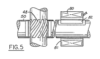
- the steering gear shown in Figure 2 operates as follows. As motor shaft 43 and spiroid motor pinion 44 rotate in response to commands from control module 26, the motor pinion propels face gear 46, which is mounted upon pinion shaft 47. Rack pinion 48, which is formed in pinion shaft 47, meshes with teeth 52 which are formed in rack 50. In sum, as motor 38 rotates in response to commands from control module 26, rack 50 will be caused to slide back and forth within housing 36, thereby steering rear roadwheels 16.
- Front steering gear 10 is similarly constructed with a rack and pinion drive, where the rack pinion is operated by the driver of the vehicle rather than by an electric motor.
- Control module 26 will track the position of rack 50 at all times by means of two sensor devices built into each steering gear.
- Each of the front and rear steering gears uses a pair of sensors for sensing the on-centre position of the steering rack by means of one sensor, while using a second sensor to sense the position of the rack at any point along its travel path.
- each steering gear is provided with an on-centre position sensor comprising, in Figure 2, Hall Effect device, 58, which is mounted within steering gear housing 36.
- the Hall Effect device is triggered by magnet 60, which is rigidly attached to the rack and which reciprocates therewith as the rack slides back and forth during steering motion.
- the Hall Effect sensor is triggered and gives a signal when magnet 60 is in proximity thereto. Accordingly, when the Hall Effect sensor is triggered, control module 26 will be alerted that steering rack 50 and hence, rear steering gear 12, is in the centre position.
- Hall Effect sensor 58 and magnet 60 comprise rear on-centre position sensor 20.
- each steering gear has yet another position sensor.
- LVDT 24 linear variable differential transformer senses the position of rack 50 at any point along its travel path and provides a steering position signal to control module 26.
- LVDT 24 includes coil 62 and plunger 64.
- the LVDT provides a voltage signal which is proportional to the position of plunger 64 within coil 62. In other words, the output of the LVDT provides a direct indication of the position of rack 50 along its travel path.
- Hall Effect sensor 58 is employed for the purpose of calibrating LVDT 24.
- the interaction of the two types of sensors is shown in Figure 4.
- control module 26 will sense that steering gear 12 is in the centre of its travel position.
- LVDT 61 may be calibrated by recording the value for the rear steering position signal from LVDT 24 at block 74 whenever the rear centre signal produced by Hall Effect device 58 is present.
- a zero steering angle signal may optionally be generated.
- Hall Effect device 18 and LVDT device 22, within front steering gear 10, will allow control module 26 to calibrate the front position signal by recording the value of the front steering position signal from LVDT 18 when the front centre signal has been received from the front Hall Effect device.
- the program within the control module's microprocessor will continue to block 76, wherein the off-centre position sensor signal will be read for the purpose of determining the steering angle.
- the front and rear steering position signals received by control module 26 whenever either of the Hall Effect devices has been triggered are recorded at block 74, and a mean value is determined for each of the series of recorded signals. This will provide an accurate indication of the front and rear steering position signals which correspond to the actual, or real, centre position of each steering gear.
- the front and rear steering gear rack positions may be determined at block 76 by comparing the instantaneous output of each LVDT with the appropriate recorded mean value corresponding to the centre position of each steering gear. For example, if each LVDT is operated at 0 to 5 volts, then 2.5 volts will correspond to the nominal centre position, and a reading of, for example, 3.5 volts from the LVDT may be compared with the 2.5 volt value to give a 1 volt differential. This will indicate a given degree of steering.
- control module 26 will realise that 2.6 volts corresponds to the centre position because 2.6 volts will be recorded at the time a signal is received from the appropriate Hall Effect sensor. Accordingly, if the steering rack were not equipped with Hall Effect on-centre sensing, the control module would have no way of realising that 2.6 volts, and not 2.5 volts, corresponds to the on-centre position of the steering gear.
- Control module 26 may further include a program for comparing the calculated mean values of the front and rear steering position signals recorded from the LVDT outputs with respective pairs of threshold values corresponding to the front and rear steering gears. If the recorded outputs fall outside the threshold values, a warning signal may be issued and the rear steering gear disabled. For example, if the nominal centre position of the rear steering gear corresponds to 2.5 volts output from the LVDT on a 5 volt scale, and if the calculated mean value of the on-centre LVDT voltage increases to 5 volts, control module 26 will have reason to suspect the accuracy of the LVDT and will, therefore, issue a warning signal or disable steering gear 12. This disablement could be accomplished by cutting off all power to motor 38.
- steering gear 12 could be disabled by means of travel limiting devices 56, comprising spring loaded pins, 59, ( Figure 2), which extend into the travel paths of inner tie-rod ends 54. Pins 59 are maintained in their extended position unless retracted by solenoids 57.
- a second warning signal may be issued in the event that either no output, or a clearly erroneous output is received by the control module from either of the Hall Effect devices when the output of the appropriate LVDT moves through the calculated mean value of the recorded LVDT signals.
- the sensors and control module comprise a calibration means for maintaining the values of the steering position signals in correspondence with the actual steering positions of the front and rear steering gears. This allows the control module to operate the rear steering gear according to at least the steering position of said front steering gear.
- Another aspect of the present invention involves a method for operating a steering system for a vehicle including the steps of sensing the centre position of a front steering gear by a first steering position sensor means, which may, for example, comprise the previously illustrated Hall Effect device, and by recording the value of a signal generated by a second steering position sensor means, for example, the illustrated LVDT, associated with the front steering gear upon sensing of the centre position by the Hall Effect sensor.
- a method according to the present invention further includes the steps of sensing the centre position of a rear steering gear associated with the rear wheels of the vehicle by a third steering position sensor means comprising, for example, the illustrated Hall Effect device, and recording the value of the signal generated by a fourth steering position means associated with the rear steering gear upon sensing of the centre position by the third sensor means.
- a method includes the step of comparing values derived from the recorded signal values from the second and fourth sensor means with the instantaneous outputs of the second and fourth sensor means to determine instantaneous steering positions of the first and second steering gears, respectively.
- this method includes recording the values of the signals generated by the LVDT means in each of the steering gears at the time the on-centre signals are received. In this manner, the recorded values may be compared with the instantaneous values from the LVDT devices so as to obtain a steering signal at any location along the travel paths of the steering gears.
- a system according to the present invention presents a further advantage over prior art systems inasmuch as the combination of LVDT and Hall Effect sensors may be used in the assembly process of the vehicle to obtain a calibration for the LVDT. Finally, the Hall Effect sensors may be used for precisely centring the steering gears whenever the alignment of either the front or rear steering gears is adjusted.
- control module 26 will be able to detect the position of rack 50 throughout its travel path.
- control system described herein may be employed for controlling an auxiliary (e.g., rear) steering gear with additional control inputs other than the steering position of the primary (e.g., front) steering gear.
- additional inputs could comprise vehicle speed, or other driver inputs such as accelerator position and brake operation.
Landscapes
- Engineering & Computer Science (AREA)
- Chemical & Material Sciences (AREA)
- Combustion & Propulsion (AREA)
- Transportation (AREA)
- Mechanical Engineering (AREA)
- Physics & Mathematics (AREA)
- Mathematical Physics (AREA)
- Theoretical Computer Science (AREA)
- Steering Control In Accordance With Driving Conditions (AREA)
- Steering-Linkage Mechanisms And Four-Wheel Steering (AREA)
Applications Claiming Priority (2)
| Application Number | Priority Date | Filing Date | Title |
|---|---|---|---|
| US07/290,679 US4936401A (en) | 1988-12-27 | 1988-12-27 | Steering system for a vehicle |
| US290679 | 1988-12-27 |
Publications (2)
| Publication Number | Publication Date |
|---|---|
| EP0376512A2 true EP0376512A2 (fr) | 1990-07-04 |
| EP0376512A3 EP0376512A3 (fr) | 1992-11-19 |
Family
ID=23117093
Family Applications (1)
| Application Number | Title | Priority Date | Filing Date |
|---|---|---|---|
| EP19890312656 Withdrawn EP0376512A3 (fr) | 1988-12-27 | 1989-12-05 | Système de direction pour véhicule |
Country Status (4)
| Country | Link |
|---|---|
| US (1) | US4936401A (fr) |
| EP (1) | EP0376512A3 (fr) |
| JP (1) | JPH02189284A (fr) |
| CA (1) | CA1319881C (fr) |
Families Citing this family (8)
| Publication number | Priority date | Publication date | Assignee | Title |
|---|---|---|---|---|
| US5163529A (en) * | 1991-04-22 | 1992-11-17 | Trw Inc. | Apparatus for sensing position of a member in a vehicle steering gear |
| US5402341A (en) * | 1992-04-06 | 1995-03-28 | Ford Motor Company | Method and apparatus for four wheel steering control utilizing tire characteristics |
| JP3028905B2 (ja) * | 1994-01-31 | 2000-04-04 | アイシン精機株式会社 | 後輪操舵アクチュエ−タ |
| US5648903A (en) * | 1995-07-10 | 1997-07-15 | Ford Global Technologies, Inc. | Four wheel steering control utilizing front/rear tire longitudinal slip difference |
| US6039143A (en) * | 1997-06-02 | 2000-03-21 | General Motors Corporation | Steerable drive axle with electrically-powered steering apparatus |
| US20070132722A1 (en) * | 2005-12-08 | 2007-06-14 | Electronics And Telecommunications Research Institute | Hand interface glove using miniaturized absolute position sensors and hand interface system using the same |
| US20090145684A1 (en) * | 2007-12-10 | 2009-06-11 | Trw Automotive U.S. Llc | Safety apparatus for rear steerable vehicle wheels |
| US12358516B1 (en) * | 2022-09-21 | 2025-07-15 | Apple Inc. | Control system for navigating during a detected event |
Family Cites Families (6)
| Publication number | Priority date | Publication date | Assignee | Title |
|---|---|---|---|---|
| JPS58170665A (ja) * | 1982-03-30 | 1983-10-07 | Nissan Motor Co Ltd | ラツクアンドピニオン式ステアリング装置 |
| US4582334A (en) * | 1982-10-13 | 1986-04-15 | Honda Giken Kogyo Kabushiki Kaisha | Steering system for vehicles |
| DE3413007A1 (de) * | 1984-04-06 | 1985-10-17 | Audi AG, 8070 Ingolstadt | Lenkeinrichtung fuer ein kraftfahrzeug |
| JPS6167666A (ja) * | 1984-09-10 | 1986-04-07 | Nissan Motor Co Ltd | 車両用操舵制御装置 |
| JPS61295175A (ja) * | 1985-06-22 | 1986-12-25 | Mazda Motor Corp | 車両の4輪操舵装置 |
| GB2194201B (en) * | 1986-08-22 | 1990-07-04 | Honda Motor Co Ltd | Steering angle detector |
-
1988
- 1988-12-27 US US07/290,679 patent/US4936401A/en not_active Expired - Fee Related
-
1989
- 1989-09-21 CA CA000612349A patent/CA1319881C/fr not_active Expired - Fee Related
- 1989-10-27 JP JP1281610A patent/JPH02189284A/ja active Pending
- 1989-12-05 EP EP19890312656 patent/EP0376512A3/fr not_active Withdrawn
Also Published As
| Publication number | Publication date |
|---|---|
| US4936401A (en) | 1990-06-26 |
| CA1319881C (fr) | 1993-07-06 |
| EP0376512A3 (fr) | 1992-11-19 |
| JPH02189284A (ja) | 1990-07-25 |
Similar Documents
| Publication | Publication Date | Title |
|---|---|---|
| EP1174328B1 (fr) | Appareil pour détecter un couple et direction assistée électrique | |
| US4735274A (en) | Automatic parallel parking system | |
| US8082078B2 (en) | Methods, systems, and computer program products for steering travel limit determination for electric power steering | |
| US6847876B2 (en) | Electric power steering apparatus | |
| EP2913247A2 (fr) | Dispositif de direction de véhicule, procédé de détermination de défaillance pour dispositif de direction de véhicule et procédé de commande pour un moteur de direction | |
| US3881567A (en) | Servo-assisted steering arrangement | |
| KR20060073960A (ko) | 조향각 센서 | |
| EP3691956A1 (fr) | Système de direction à commande électrique doté d'un actionneur de rétroaction comprenant des capteurs de position de rotor en mode veille redondants | |
| US4936401A (en) | Steering system for a vehicle | |
| US6648096B2 (en) | Method and device for determining a steering angle of a motor vehicle | |
| EP0376456B1 (fr) | Détecteur de position d'un système de direction | |
| US6163746A (en) | Device for determining a steering angle of a motor vehicle | |
| KR20040028664A (ko) | 액면 검출 장치 | |
| EP0397324B1 (fr) | Procédé pour la commande de braquage de roues arrières | |
| EP0376557A2 (fr) | Système de direction pour les roues arrières d'un véhicule | |
| US20020079156A1 (en) | Hall effect torque sensor | |
| KR20200107484A (ko) | 자동차 조향 장치의 랙바 제어 장치 및 방법 | |
| JP2008519252A (ja) | 自動車の操舵角を規定するための方法及び装置 | |
| JP6065653B2 (ja) | 電動パワーステアリング装置並びに電動パワーステアリング装置の調整装置及び調整方法 | |
| US20080245600A1 (en) | Electric Power Steering Apparatus | |
| US11447179B2 (en) | Method for determining the rack-and-pinion position in a steering system having an electric servomotor | |
| US20060042411A1 (en) | Steering system | |
| EP1666338B1 (fr) | Dispositif de détection de couple | |
| JP4483330B2 (ja) | 電動パワーステアリング装置 | |
| JP2002039877A (ja) | トルク検出装置及び電動パワーステアリング装置 |
Legal Events
| Date | Code | Title | Description |
|---|---|---|---|
| PUAI | Public reference made under article 153(3) epc to a published international application that has entered the european phase |
Free format text: ORIGINAL CODE: 0009012 |
|
| AK | Designated contracting states |
Kind code of ref document: A2 Designated state(s): DE FR GB |
|
| PUAL | Search report despatched |
Free format text: ORIGINAL CODE: 0009013 |
|
| AK | Designated contracting states |
Kind code of ref document: A3 Designated state(s): DE FR GB |
|
| 17P | Request for examination filed |
Effective date: 19930427 |
|
| 17Q | First examination report despatched |
Effective date: 19941027 |
|
| STAA | Information on the status of an ep patent application or granted ep patent |
Free format text: STATUS: THE APPLICATION IS DEEMED TO BE WITHDRAWN |
|
| 18D | Application deemed to be withdrawn |
Effective date: 19960910 |