EP0376557A2 - Système de direction pour les roues arrières d'un véhicule - Google Patents
Système de direction pour les roues arrières d'un véhicule Download PDFInfo
- Publication number
- EP0376557A2 EP0376557A2 EP89313110A EP89313110A EP0376557A2 EP 0376557 A2 EP0376557 A2 EP 0376557A2 EP 89313110 A EP89313110 A EP 89313110A EP 89313110 A EP89313110 A EP 89313110A EP 0376557 A2 EP0376557 A2 EP 0376557A2
- Authority
- EP
- European Patent Office
- Prior art keywords
- steering
- vehicle
- gear
- steering gear
- motor drive
- Prior art date
- Legal status (The legal status is an assumption and is not a legal conclusion. Google has not performed a legal analysis and makes no representation as to the accuracy of the status listed.)
- Granted
Links
Images

Classifications
-
- B—PERFORMING OPERATIONS; TRANSPORTING
- B62—LAND VEHICLES FOR TRAVELLING OTHERWISE THAN ON RAILS
- B62D—MOTOR VEHICLES; TRAILERS
- B62D5/00—Power-assisted or power-driven steering
- B62D5/04—Power-assisted or power-driven steering electrical, e.g. using an electric servo-motor connected to, or forming part of, the steering gear
- B62D5/0421—Electric motor acting on or near steering gear
- B62D5/0424—Electric motor acting on or near steering gear the axes of motor and final driven element of steering gear, e.g. rack, being parallel
-
- B—PERFORMING OPERATIONS; TRANSPORTING
- B62—LAND VEHICLES FOR TRAVELLING OTHERWISE THAN ON RAILS
- B62D—MOTOR VEHICLES; TRAILERS
- B62D15/00—Steering not otherwise provided for
- B62D15/02—Steering position indicators ; Steering position determination; Steering aids
- B62D15/021—Determination of steering angle
- B62D15/0225—Determination of steering angle by measuring on a steering gear element, e.g. on a rack bar
-
- B—PERFORMING OPERATIONS; TRANSPORTING
- B62—LAND VEHICLES FOR TRAVELLING OTHERWISE THAN ON RAILS
- B62D—MOTOR VEHICLES; TRAILERS
- B62D7/00—Steering linkage; Stub axles or their mountings
- B62D7/06—Steering linkage; Stub axles or their mountings for individually-pivoted wheels, e.g. on king-pins
- B62D7/14—Steering linkage; Stub axles or their mountings for individually-pivoted wheels, e.g. on king-pins the pivotal axes being situated in more than one plane transverse to the longitudinal centre line of the vehicle, e.g. all-wheel steering
- B62D7/15—Steering linkage; Stub axles or their mountings for individually-pivoted wheels, e.g. on king-pins the pivotal axes being situated in more than one plane transverse to the longitudinal centre line of the vehicle, e.g. all-wheel steering characterised by means varying the ratio between the steering angles of the steered wheels
- B62D7/1581—Steering linkage; Stub axles or their mountings for individually-pivoted wheels, e.g. on king-pins the pivotal axes being situated in more than one plane transverse to the longitudinal centre line of the vehicle, e.g. all-wheel steering characterised by means varying the ratio between the steering angles of the steered wheels characterised by comprising an electrical interconnecting system between the steering control means of the different axles
Definitions
- This invention relates to a steering system for the rear wheels of a vehicle, and more particularly to a subsystem for selectively overriding the rear steering system prime mover so as to prevent the rear steering gear from exceeding a predetermined fractional component of its total angular range in the event that the operating condition of the vehicle warrants such limitation.
- Rear wheel steering systems typically respond to steering of the front wheels of the vehicle. Certain systems respond to other vehicle inputs such as steering torque, vehicle speed, transmission gear or other parameters.
- U.S. 4,671,523 discloses a system which immobilises the rear steering gear in response to inputs from a steering torque sensor associated with the front wheels and a front wheel turn angle sensor.
- the system of the '523 patent limits the usefulness of the rear steering system because it is capable only of disabling the rear steering gear entirely; it will not serve to restrict the range of authority of the steering gear while still allowing a limited steering capability of the rear steering gear.
- U.S. 4,566,711 and U.S. 4,705,135 disclose shaft-driven rear wheel steering systems in which a drive shaft couples the front and rear steering gears of a vehicle.
- the '711 and '135 patents further disclose motor operated devices for changing the front-to-rear steering ratio. In the event that these motor-driven ratio changing devices were to malfunction, a serious problem could be encountered by the driver because the driver could be unaware of the resetting of the front-to-front/rear steering ratio, and as a result, vehicle handling changes could cause a loss of vehicle control.
- U.S. 4,105,086 and U.S. 4,657,102 disclose another type of system in which the power for actuating the rear wheel steering system is derived from a hydraulically controlled means.
- the '086 patent discloses a linkage-operated system
- the '102 patent discloses a purely hydraulically operated system.
- Each of the systems disclosed in the '086 and '102 patents suffers from a potential infirmity inasmuch as a malfunction in the control hydraulics of the systems could cause an unexpected slewing of the rear wheels in one direction or another, with concomitant loss of vehicle control.
- a steering system according to this invention will have a limited capacity to steer the rear wheels once the vehicle has exceeded a threshold speed.
- a steering system for the rear wheels of a vehicle comprises a steering gear for steering the rear wheels within an angular range of authority, with the steering gear comprising a motor drive for positioning the rear wheels.
- a steering system according to this invention further comprises control means for operating the steering gear, with the control means comprising means for sensing at least one vehicle operating parameter and means responsive to the sensed parameter for overriding the steering gear's motor drive so as to prevent the steering gear from exceeding a predetermined fractional component of the angular steering range of authority.
- the sensed operating parameter may comprise the velocity of the vehicle so that the steering capability of the motor drive within the rear steering gear will be limited according to the velocity of the vehicle.
- the sensed operating parameter may comprise the transmission gear in which the vehicle is being operated so that the steering capability of the motor drive will be limited according to the transmission operating condition.
- a motor drive employed with a system according to the present invention may comprise an electric motor driving a gear set operatively connected with the rear wheels of the vehicle.
- a steering system for the rear wheels of a vehicle according to the present invention comprises a motor driven, dual-range steering gear for steering the rear wheels, with the steering gear being operable within greater and lesser ranges of authority, with each such range corresponding to a different predetermined maximum steering angle, and control means for operating the steering gear, with the control means comprising means for sensing the speed of the vehicle and means responsive to the sensed vehicle speed for preventing the motor drive from exceeding the maximum steering angle corresponding to the lesser range in the event that a threshold speed has been exceeded.
- the means for preventing the motor drive from exceeding the prescribed maximum steering angle corresponding to the lesser range may comprise a limit mechanism for impeding the motion of the steering gear.
- This limit mechanism may comprise an electromechanical travel limiting block adapted to interact with the sliding member contained within the steering gear.
- rear steering gear 10 is coupled to a pair of spindles, 16, by means of tie rods, 14. Accordingly, as the tie rods are driven reciprocably by steering gear 10, road wheels 12 will be caused to rotate about the kingpin axes defined by ball joints 18 and as a result road wheels 12 will be steered by steering gear 10.
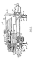
- FIG. 2 illustrates the internal parts of a steering gear suitable for use with a system according to the present invention.
- a system according to the present invention would be useful not only with the illustrated gear but also with other types of steering gears employing hydraulic, mechanical or electrical operating systems and prime movers.
- the steering gear shown in Figure 2 has an electrically driven prime mover. Accordingly, motor 20 drives motor pinion 22, which in turn meshes with face gear 24.
- the face gear is mounted to a common shaft with rack pinion 26, which in turn meshes with teeth formed on rack 28. Accordingly, as motor 20 revolves, rack 28 will reciprocate.
- An inner tie rod end, 40 is mounted at either end of rack 28. These tie rod ends allow tie rods 14 to be mounted to steering gear 10.
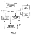
- control module 18 ( Figure 3) will receive inputs from rear steering gear position sensor 42, which in this case comprise a linear variable differential transformer (LVDT).
- the LVDT is coupled between rack 28 and the steering gear's housing so that reciprocation of the rack will be accompanied by a change in the voltage level of the signal which is output by the LVDT.
- Control module 18 also receives inputs from front steering gear position sensor 44, vehicle speed sensor 46 and transmission gear sensor 48.
- a system according to the present invention could be employed with or without speed sensor 46 or transmission gear sensor 48. It will be further appreciated that a system according to the present invention could be employed with yet other types of sensors capable of detecting appropriate vehicular operating parameters.
- control module 18 provides control signals to rear steering gear drive motor 20.
- control module 18 senses the front steering gear position and speed or transmission gear being used and provides a rear steering signal.
- a number of known control strategies have been employed for determining a desired angular steering position of the rear roadwheels required for any particular front wheel steering position at a given speed or other vehicular operating condition.
- rear wheel steering is usually subject to a greater angular range of authority. For example, at low speeds, it is known to steer the rear wheels with some systems in excess of 5/ from the straight-ahead position.
- the present invention provides a means for positively preventing the steering gear's motor drive or other prime mover from exceeding the maximum steering angle corresponding to a lesser range, for example 1.5/ of steering angle, in the event that a threshold speed has been exceeded.
- a first threshold for example, 10 mph
- a lower threshold for example, 5 mph
- Each travel limiting solenoid comprises a coil, 32, which acts upon a plunger, 34.
- Each plunger has a crown 26 applied thereto.
- the plunger and crown are biased into the blocking position by means of biasing springs 38.
- biasing springs 38 Accordingly, in the event that no signal is received by coil 32 from control module 18, each travel limiting solenoid will automatically be urged into the limiting position by means of biasing springs 38.
- the wiring connections between travel limiting solenoids 30 and control module 32 become compromised -- e.g., open circuited, the travel limiting solenoids will be automatically applied.
- control module 18 will receive vehicle speed information from speed sensor 46 and transmission gear selection information from transmission gear sensor 48. Accordingly, in the event that the vehicle speed is less than a threshold which is appropriate for the chosen direction of movement, whether forward or reverse, travel limiting solenoids 30 will be energised, thereby removing crowns 26 from the path of inner tie rod ends 40. If, however, the vehicle speed exceeds a given threshold appropriate for the direction of movement, power will not be provided to the travel limiting solenoids and, as a result, the maximum steering angle will be limited to a lesser angular range.
- This control scheme thus operates the rear steering gear as a dual range steering gear with greater and lesser angular ranges of authority, with each range corresponding to a different predetermined maximum rear wheel steering angle.
Landscapes
- Engineering & Computer Science (AREA)
- Chemical & Material Sciences (AREA)
- Combustion & Propulsion (AREA)
- Transportation (AREA)
- Mechanical Engineering (AREA)
- Steering Control In Accordance With Driving Conditions (AREA)
- Steering-Linkage Mechanisms And Four-Wheel Steering (AREA)
Applications Claiming Priority (2)
| Application Number | Priority Date | Filing Date | Title |
|---|---|---|---|
| US07/290,209 US5004063A (en) | 1988-12-27 | 1988-12-27 | Steering system for the rear wheels of a vehicle |
| US290209 | 1988-12-27 |
Publications (3)
| Publication Number | Publication Date |
|---|---|
| EP0376557A2 true EP0376557A2 (fr) | 1990-07-04 |
| EP0376557A3 EP0376557A3 (en) | 1990-12-19 |
| EP0376557B1 EP0376557B1 (fr) | 1995-02-01 |
Family
ID=23114983
Family Applications (1)
| Application Number | Title | Priority Date | Filing Date |
|---|---|---|---|
| EP89313110A Expired - Lifetime EP0376557B1 (fr) | 1988-12-27 | 1989-12-14 | Système de direction pour les roues arrières d'un véhicule |
Country Status (5)
| Country | Link |
|---|---|
| US (1) | US5004063A (fr) |
| EP (1) | EP0376557B1 (fr) |
| JP (1) | JPH02189283A (fr) |
| CA (1) | CA1326202C (fr) |
| DE (1) | DE68920983D1 (fr) |
Cited By (5)
| Publication number | Priority date | Publication date | Assignee | Title |
|---|---|---|---|---|
| EP0470424B1 (fr) * | 1990-08-07 | 1997-10-15 | FIAT AUTO S.p.A. | Moyens pour limiter l'angle de braquage des roues d'un véhicule |
| WO2006013382A1 (fr) * | 2004-08-06 | 2006-02-09 | Electro Systems Limited | Appareil de direction ameliore |
| EP2457806A1 (fr) * | 2010-11-25 | 2012-05-30 | Audi AG | Système de direction |
| CN107521560A (zh) * | 2017-09-13 | 2017-12-29 | 无锡商业职业技术学院 | 一种基于单级行星齿轮传动的差动变压器式转向盘角度传感器 |
| WO2026003863A1 (fr) * | 2024-06-27 | 2026-01-02 | Ve Commercial Vehicles Ltd. | Système de braquage des roues arrière à assistance électrique pour petit véhicule utilitaire |
Families Citing this family (6)
| Publication number | Priority date | Publication date | Assignee | Title |
|---|---|---|---|---|
| US5207287A (en) * | 1990-06-06 | 1993-05-04 | Koyo Seiko Co., Ltd. | Four-wheel steering apparatus |
| DE19908323B4 (de) * | 1999-02-26 | 2010-01-07 | GM Global Technology Operations, Inc. (GTO), Detroit | Gelenkte Fahrzeugachse |
| US20060254237A1 (en) * | 2005-05-16 | 2006-11-16 | Ricketts Jonathan E | Agricultural combine |
| DE102019133917B4 (de) * | 2019-12-11 | 2022-11-03 | Bayerische Motoren Werke Aktiengesellschaft | Verfahren und Vorrichtung zur Steuerung einer Hinterachslenkung |
| DE102022209105A1 (de) * | 2022-09-01 | 2024-03-07 | Volkswagen Aktiengesellschaft | Sensorvorrichtung für einen Radaktuator eines Steer-by-Wire-Systems eines Fahrzeuges, Radaktuator, Steer-by-Wire-System, Fahrzeug und Verfahren zum Bestimmen einer Position einer Lenkstange eines Fahrzeuges |
| DE102023133807A1 (de) * | 2023-12-04 | 2025-06-05 | Schaeffler Technologies AG & Co. KG | Lenkeinheit für Fahrzeug |
Family Cites Families (16)
| Publication number | Priority date | Publication date | Assignee | Title |
|---|---|---|---|---|
| JPS5261024A (en) * | 1975-11-13 | 1977-05-20 | Takemochi Ishii | Steering control system for fourrwheel steered vehicle |
| US4552239A (en) * | 1982-10-26 | 1985-11-12 | Mazda Motor Corporation | Four-wheel steering device for vehicle |
| DE3338702A1 (de) * | 1982-10-28 | 1984-05-03 | Toyo Kogyo Co. Ltd., Hiroshima | Vierrad-lenkung fuer fahrzeuge |
| JPS6078870A (ja) * | 1983-10-05 | 1985-05-04 | Mazda Motor Corp | 車両の4輪操舵装置 |
| JPS6085074A (ja) * | 1983-10-17 | 1985-05-14 | Honda Motor Co Ltd | 車両の前後輪操舵装置 |
| GB2194927B (en) * | 1984-02-28 | 1988-07-27 | Mitsubishi Motors Corp | Rear wheel steering apparatus |
| DE3413007A1 (de) * | 1984-04-06 | 1985-10-17 | Audi AG, 8070 Ingolstadt | Lenkeinrichtung fuer ein kraftfahrzeug |
| JPS6127770A (ja) * | 1984-07-17 | 1986-02-07 | Nissan Motor Co Ltd | 後輪操舵装置 |
| FR2576269B1 (fr) * | 1985-01-24 | 1989-02-17 | Honda Motor Co Ltd | Dispositif de direction des roues avant et arriere d'un vehicule |
| JPS61235275A (ja) * | 1985-04-10 | 1986-10-20 | Honda Motor Co Ltd | 前後輪操舵車両の後輪操舵制御方法 |
| JPS61295175A (ja) * | 1985-06-22 | 1986-12-25 | Mazda Motor Corp | 車両の4輪操舵装置 |
| JPS628869A (ja) * | 1985-07-08 | 1987-01-16 | Mazda Motor Corp | 車両の4輪操舵装置 |
| US4874054A (en) * | 1986-08-27 | 1989-10-17 | Mazda Motor Corporation | Control in a vehicle four wheel steering system |
| JPS63125476A (ja) * | 1986-11-15 | 1988-05-28 | Fuji Heavy Ind Ltd | 電動式後輪操舵装置 |
| JPH0624940B2 (ja) * | 1986-12-04 | 1994-04-06 | 三菱電機株式会社 | 電動式後輪操舵装置 |
| JP2538939B2 (ja) * | 1987-09-25 | 1996-10-02 | 日産自動車株式会社 | 車両の舵角制御装置 |
-
1988
- 1988-12-27 US US07/290,209 patent/US5004063A/en not_active Expired - Fee Related
-
1989
- 1989-09-21 CA CA000612347A patent/CA1326202C/fr not_active Expired - Fee Related
- 1989-10-24 JP JP1275135A patent/JPH02189283A/ja active Pending
- 1989-12-14 DE DE68920983T patent/DE68920983D1/de not_active Expired - Lifetime
- 1989-12-14 EP EP89313110A patent/EP0376557B1/fr not_active Expired - Lifetime
Cited By (6)
| Publication number | Priority date | Publication date | Assignee | Title |
|---|---|---|---|---|
| EP0470424B1 (fr) * | 1990-08-07 | 1997-10-15 | FIAT AUTO S.p.A. | Moyens pour limiter l'angle de braquage des roues d'un véhicule |
| WO2006013382A1 (fr) * | 2004-08-06 | 2006-02-09 | Electro Systems Limited | Appareil de direction ameliore |
| EP2457806A1 (fr) * | 2010-11-25 | 2012-05-30 | Audi AG | Système de direction |
| CN107521560A (zh) * | 2017-09-13 | 2017-12-29 | 无锡商业职业技术学院 | 一种基于单级行星齿轮传动的差动变压器式转向盘角度传感器 |
| CN107521560B (zh) * | 2017-09-13 | 2023-12-01 | 无锡商业职业技术学院 | 一种基于单级行星齿轮传动的差动变压器式转向盘角度传感器 |
| WO2026003863A1 (fr) * | 2024-06-27 | 2026-01-02 | Ve Commercial Vehicles Ltd. | Système de braquage des roues arrière à assistance électrique pour petit véhicule utilitaire |
Also Published As
| Publication number | Publication date |
|---|---|
| US5004063A (en) | 1991-04-02 |
| JPH02189283A (ja) | 1990-07-25 |
| CA1326202C (fr) | 1994-01-18 |
| EP0376557A3 (en) | 1990-12-19 |
| DE68920983D1 (de) | 1995-03-16 |
| EP0376557B1 (fr) | 1995-02-01 |
Similar Documents
| Publication | Publication Date | Title |
|---|---|---|
| EP1332946B1 (fr) | Actionneur pour volant de direction | |
| US6899196B2 (en) | Driver interface system for steer-by-wire system | |
| EP0858942B1 (fr) | Dispositif de direction pour véhicule | |
| EP0596167B1 (fr) | Système de direction assisté à ratio variable pour véhicule automobile | |
| DE69801849T2 (de) | Lenkeinrichtung für ein Fahrzeug | |
| US5992556A (en) | Method and apparatus for damping control of an electric assist steering system with vehicle speed signal loss feature | |
| EP0787642B1 (fr) | Procédé et appareil pour la compensation d'effet du couple entraínant sur la direction | |
| CA1326202C (fr) | Detection pour roues arriere d'un vehicule | |
| JP3935970B2 (ja) | 油圧パワーアシスト機構付きのパワーステアリング装置 | |
| JPH07309249A (ja) | 電気アシスト・ステアリング・システムの制御方法及び装置 | |
| US4987963A (en) | Steering gear for the roadwheels of a vehicle | |
| EP0522555B1 (fr) | Appareil de direction de roues arrières pour véhicules à roues | |
| EP1268258B1 (fr) | Systeme de direction par cables avec perception de la route | |
| EP0376456B1 (fr) | Détecteur de position d'un système de direction | |
| US5096011A (en) | Steering gear and system for automotive vehicle | |
| US6543568B2 (en) | Dual variable-tooth rack and single pinion steering system | |
| EP0376512A2 (fr) | Système de direction pour véhicule | |
| EP1697201B1 (fr) | Procede et produit informatique dans un dispositif de conduite de vehicule | |
| EP0376458A2 (fr) | Système de direction pour véhicule automobile | |
| JP3156570B2 (ja) | 車両の後輪操舵装置 | |
| JPS6294471A (ja) | ステアリング制御器 | |
| JPH0221987B2 (fr) | ||
| JPH043353B2 (fr) | ||
| JP2689450B2 (ja) | 車両の四輪操舵装置 | |
| JPH043354B2 (fr) |
Legal Events
| Date | Code | Title | Description |
|---|---|---|---|
| PUAI | Public reference made under article 153(3) epc to a published international application that has entered the european phase |
Free format text: ORIGINAL CODE: 0009012 |
|
| AK | Designated contracting states |
Kind code of ref document: A2 Designated state(s): DE FR GB |
|
| PUAL | Search report despatched |
Free format text: ORIGINAL CODE: 0009013 |
|
| AK | Designated contracting states |
Kind code of ref document: A3 Designated state(s): DE FR GB |
|
| 17P | Request for examination filed |
Effective date: 19910525 |
|
| 17Q | First examination report despatched |
Effective date: 19930329 |
|
| GRAA | (expected) grant |
Free format text: ORIGINAL CODE: 0009210 |
|
| AK | Designated contracting states |
Kind code of ref document: B1 Designated state(s): DE FR GB |
|
| PG25 | Lapsed in a contracting state [announced via postgrant information from national office to epo] |
Ref country code: FR Effective date: 19950201 |
|
| REF | Corresponds to: |
Ref document number: 68920983 Country of ref document: DE Date of ref document: 19950316 |
|
| PG25 | Lapsed in a contracting state [announced via postgrant information from national office to epo] |
Ref country code: DE Effective date: 19950503 |
|
| EN | Fr: translation not filed | ||
| REG | Reference to a national code |
Ref country code: GB Ref legal event code: 746 Effective date: 19951107 |
|
| PLBE | No opposition filed within time limit |
Free format text: ORIGINAL CODE: 0009261 |
|
| STAA | Information on the status of an ep patent application or granted ep patent |
Free format text: STATUS: NO OPPOSITION FILED WITHIN TIME LIMIT |
|
| 26N | No opposition filed | ||
| PGFP | Annual fee paid to national office [announced via postgrant information from national office to epo] |
Ref country code: GB Payment date: 19971126 Year of fee payment: 9 |
|
| PG25 | Lapsed in a contracting state [announced via postgrant information from national office to epo] |
Ref country code: GB Free format text: LAPSE BECAUSE OF NON-PAYMENT OF DUE FEES Effective date: 19981214 |
|
| GBPC | Gb: european patent ceased through non-payment of renewal fee |
Effective date: 19981214 |