EP0378514A2 - Anschlagpresse - Google Patents
Anschlagpresse Download PDFInfo
- Publication number
- EP0378514A2 EP0378514A2 EP19900810008 EP90810008A EP0378514A2 EP 0378514 A2 EP0378514 A2 EP 0378514A2 EP 19900810008 EP19900810008 EP 19900810008 EP 90810008 A EP90810008 A EP 90810008A EP 0378514 A2 EP0378514 A2 EP 0378514A2
- Authority
- EP
- European Patent Office
- Prior art keywords
- eccentric
- stop
- guideway
- eccentric shaft
- crimping press
- Prior art date
- Legal status (The legal status is an assumption and is not a legal conclusion. Google has not performed a legal analysis and makes no representation as to the accuracy of the status listed.)
- Granted
Links
- 238000002788 crimping Methods 0.000 title claims abstract description 12
- 238000005096 rolling process Methods 0.000 claims description 5
- 239000004020 conductor Substances 0.000 claims description 2
- 238000010276 construction Methods 0.000 abstract description 3
- 238000010586 diagram Methods 0.000 description 3
- 238000003825 pressing Methods 0.000 description 3
- 238000006073 displacement reaction Methods 0.000 description 2
- 230000005540 biological transmission Effects 0.000 description 1
- 230000007423 decrease Effects 0.000 description 1
- 230000001419 dependent effect Effects 0.000 description 1
- 239000002655 kraft paper Substances 0.000 description 1
- 239000002184 metal Substances 0.000 description 1
- 238000000034 method Methods 0.000 description 1
- 230000010355 oscillation Effects 0.000 description 1
- 230000001360 synchronised effect Effects 0.000 description 1
Images
Classifications
-
- B—PERFORMING OPERATIONS; TRANSPORTING
- B30—PRESSES
- B30B—PRESSES IN GENERAL
- B30B9/00—Presses specially adapted for particular purposes
-
- B—PERFORMING OPERATIONS; TRANSPORTING
- B30—PRESSES
- B30B—PRESSES IN GENERAL
- B30B1/00—Presses, using a press ram, characterised by the features of the drive therefor, pressure being transmitted directly, or through simple thrust or tension members only, to the press ram or platen
- B30B1/26—Presses, using a press ram, characterised by the features of the drive therefor, pressure being transmitted directly, or through simple thrust or tension members only, to the press ram or platen by cams, eccentrics, or cranks
-
- Y—GENERAL TAGGING OF NEW TECHNOLOGICAL DEVELOPMENTS; GENERAL TAGGING OF CROSS-SECTIONAL TECHNOLOGIES SPANNING OVER SEVERAL SECTIONS OF THE IPC; TECHNICAL SUBJECTS COVERED BY FORMER USPC CROSS-REFERENCE ART COLLECTIONS [XRACs] AND DIGESTS
- Y10—TECHNICAL SUBJECTS COVERED BY FORMER USPC
- Y10T—TECHNICAL SUBJECTS COVERED BY FORMER US CLASSIFICATION
- Y10T74/00—Machine element or mechanism
- Y10T74/18—Mechanical movements
- Y10T74/18056—Rotary to or from reciprocating or oscillating
- Y10T74/18248—Crank and slide
- Y10T74/18256—Slidable connections [e.g., scotch yoke]
Definitions
- the present invention relates to a stop or crimping press for connecting contact parts to a conductor, in which an electric motor drives an eccentric shaft with an eccentric pin via a reduction gear, said pin running in a guide that moves the plunger up and down with the crimping tool.
- stop presses which work with toggle lever systems, tend to decline because they have a large number of wearing parts and, accordingly, a voluminous construction with a relatively high dimensional accuracy stop presses with eccentrics are more common.
- a large reduction ratio of the gear is required, for example by means of spur gear or worm gear.
- the large reduction requires that the drive motor in each work cycle from 0 to about 4,000-5,000 rpm. accelerates and then it goes to 0 rpm. slowed down. Accordingly, the drive motors are subjected to enormous loads and tend to overheat, which considerably reduces the service life.
- the present invention therefore has as its object to improve a stop or crimping press of the type mentioned in such a way that the stroke of the ram changes in relation to the path of the circular movement of the eccentric pin during the downward movement to bottom dead center in such a way that for the approximately last one 10% of the stroke is available about a quarter turn of the eccentric shaft.
- a synchronous electric motor 2 is mounted on a machine frame. This acts via a reduction gear 3 on an eccentric shaft 10 mounted in the machine frame.
- the eccentric shaft carries the eccentric with an eccentric pin.
- the eccentric pin lies in a guide which is part of a plunger which can be moved vertically up and down.
- the plunger carries an interchangeable tool with which metal contacts, such as through connectors, end connectors, cable lugs and flag connectors, are pressed onto cables, in particular also stranded cables.
- the electronic control is housed in the hinged box 4.
- the eccentric shaft 10 is shown in detail in FIG. This is provided at the end with a flange 11 in which an eccentrically arranged bore is made.
- the eccentric pin 13 is held in the bore 12 by means of a press fit.
- a radial roller bearing 14 is pushed onto the part of the eccentric pin 13 protruding from the bore 12.
- the rolling bearing fits into the eccentric guide 15 or guideway with little play.
- the eccentric guide 15 is directly in the ram 3 let in.
- the eccentric guide As is known, a circular movement can be broken down into two sinusoidal, oscillating movements in the vertical and horizontal directions.
- the vertical component is used to move the ram and the tool attached to it, while the horizontal component is received in the guideway and makes no contribution to the power transmission of the tool to the workpiece.
- the guideway for the eccentric bolt is straight and horizontal and is either open by an upper and lower slide plate or a closed guideway. In the starting position, the eccentric is in the top dead center position and the ram in the top stroke position, the eccentric pin being in the middle of the guideway.
- the eccentric guide or guideway 15 has a lower guide area 16 which curves in a circular upward direction from the center with respect to the entire horizontal displacement area and an upper guide area 17 which runs horizontally in the opposite direction from said center.
- the total stroke of the tool is predetermined by the movement of the eccentric pin 13 and is twice the distance a between the axis of the eccentric shaft 10 and the axis of the eccentric pin 13. At this distance a, the axis of the eccentric pin 13 also moves from the center of the guideway to both sides . From top dead center at The rolling bearing 14 now rolls to the right on the lower curved guideway region 16.
- the plunger in which the guideway is embedded is additionally moved downwards by the distance b, namely the distance by which the point of contact of the roller bearing has moved vertically upwards from the lowest point 18.
- the radius of curvature of the lower curved guideway area is larger than the diameter of the rolling bearing 14 rolling in the guideway.
Landscapes
- Engineering & Computer Science (AREA)
- Mechanical Engineering (AREA)
- Press Drives And Press Lines (AREA)
- Presses And Accessory Devices Thereof (AREA)
- Graft Or Block Polymers (AREA)
Abstract
Description
- Die vorliegende Erfindung betrifft eine Anschlag- beziehungsweise Crimppresse zur Verbindung von Kontaktteilen mit einem Leiter, bei der ein Elektromotor über ein Untersetzungsgetriebe eine Exzenterwelle mit einem Exzenterzapfen treibt, wobei dieser Zapfen in einer Führung läuft, die den Stössel mit dem Crimpwerkzeug auf und nieder bewegt.
- Anschlag- oder Crimppressen der vorgenannten Art sind in diversen Ausführungen auf dem Markt erhältlich. Grundsätzlich unterscheidet man Pressen, die mit einem Exzenter und solche, die mittels einem Kniehebelsystem arbeiten. Während Anschlagpressen, die mit Kniehebelsystemen arbeiten eher rückläufig sind, da sie eine Vielzahl von Verschleissteilen aufweisen und entsprechend eine voluminöse Konstruktion mit relativ grosser Massgenauigkeit be dingen, sind Anschlagpressen mit Exzentern stärker verbreitet. Weil die Krafteinleitung relativ ungünstig ist, wird ein grosses Untersetzungsverhältnis des Getriebes benötigt, beispielsweise mittels Stirnrad- oder Schneckengetriebe. Die grosse Untersetzung verlangt jedoch, dass der Antriebsmotor bei jedem Arbeitszyklus von 0 auf ca. 4′000-5′000 U/min. beschleunigt und danach wird auf 0 U/min. abgebremst. Entsprechend werden die Antriebsmotoren gewaltig belastet und neigen zu Ueberhitzung, wodurch die Lebensdauer erheblich reduziert wird.
- Die vorliegende Erfindung stellt sich daher die Aufgabe, eine Anschlag- oder Crimppresse der eingangs genannten Art so zu verbessern, dass der Hubweg des Stössels im Verhältnis zum Weg der Kreisbewegung des Exzenterzapfens bei der Abwärtsbewegung zum unteren Totpunkt sich derart verändert, dass für die annähernd letzten 10% des Hubweges zirka eine Vierteldrehung der Exzenterwelle zur Verfügung steht.
- Diese Aufgabe löst eine Anschlag- oder Crimppresse mit den Merkmalen des Patentanspruches 1.
- Da somit das Kraft-Weg-Verhältnis sehr viel günstiger ist, kann mit einer sehr viel kleineren Untersetzung gearbeitet werden. Folglich braucht der Antriebsmotor eine erheblich geringere Tourenzahl, um in der gleichen Zykluszeit einen Pressvorgang durchzuführen. Bei einer Anschlagpresse gemäss der Erfindung wird mit einer maximalen Tourenzahl von 1100 U/min. gearbeitet und eine Zykluszeit von 0,26 sec. erreicht. Die erheblich geringere Untersetzung erlaubt es erstmals, eine Anschlagpresse mit einem Zahnriemengetriebe zu realisieren. Weitere vorteilhafte Ausführungsformen gehen aus den abhängigen Ansprüchen hervor.
- Es zeigt:
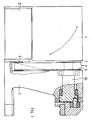
- Figur 1 eine schematische Darstellung der Anschlagpresse;
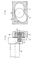
- Figur 2 einen Schnitt durch die Exzenterwelle und den in der Exzenterführung gelagerten Exzenterzapfen;
- Figur 3 einen Schnitt durch die Exzenterführung entlang der Linie II-II in Figur 2;
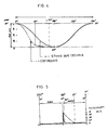
- Figur 4 den Hubweg des Exzenterzapfens in Abhängigkeit der Winkellage der Exzenterwelle und
- Figur 5 die Kennlinie der Kraft in Abhängigkeit der Winkellage der Exzenterwelle.
- Es wurde bewusst auf die detallierte Gesamtdarstellung der Anschlagpresse verzichtet, da deren Bauweise bekannt und für die Erfindung nicht direkt von Bedeutung ist. Trotzdem sei hier der prinzipielle Aufbau kurz erläutert.
- An einen Maschinenrahmen ist ein Synchron-Elektromotor 2 montiert. Dieser wirkt über ein Untersetzungsgetriebe 3 auf eine im Maschinenrahmen gelagerte Exzenterwelle 10. Die Exzenterwelle trägt den Exzenter mit einem Exzenterzapfen. Der Exzenterzapfen liegt in einer Führung der Teil eines vertikal auf und nieder bewegbaren Stössels ist. Der Stössel trägt ein auswechselbares Werkzeug mit dem Metallkontakte, wie Durchgangsverbinder, Endverbinder, Kabelschuhe und Fahnenstecker auf Kabel , insbesondere auch Litzenkabel aufgepresst werden. Im aufklappbaren Kasten 4 ist die elektronische Steuerung untergebracht.
- Im Detail dargestellt ist in Figur 2 die Exzenterwelle 10 gezeigt. Diese ist endseitig mit einem Flansch 11 versehen, indem eine exzentrisch angeordnete Bohrung angebracht ist. In der Bohrung 12 ist mittels Press-Sitz der Exzenterzapfen 13 gehalten. Auf dem aus der Bohrung 12 herausragenden Teil des Exzenterzapfens 13 ist ein radiales Wälzlager 14 aufgeschoben. Das Wälzlager passt mit geringem Spiel in die Exzenterführung 15 beziehungsweise Führungsbahn. Die Exzenterführung 15 ist direkt im Stössel 3 eingelassen.
- Bevor die erfindungswesentliche Führungsbahn beschrieben wird, sei kurz die Exzenterführung gemäss dem Stand der Technik erläutert. Bekanntlich kann eine kreisförmige Bewegung in zwei sinusförmig, oszillierende Bewegungen in vertikaler und horizontaler Richtung zerlegt werden. Die vertikale Komponente wird zur Bewegung des Stössels und den daran befestigten Werkzeug genutzt, während die horizontale Komponente in der Führungsbahn aufgenommen wird und keinen Beitrag zur Kraftübertragung des Werkzeuges auf das Werkstück ausübt. Die Führungsbahn für den Exzenterbolzen ist gradlinig horizontal und entweder offen durch eine obere und untere Gleitplatte oder als geschlossene Führungsbahn ausgebildet. In der Ausgangslage befindet sich der Exzenter in der oberen Totpunktlage und der Stössel in der obersten Hublage, wobei der Exzenterzapfen sich in der Mitte der Führungsbahn stellt. Bei seiner Bewegung im Uhrzeigersinn wälzt sich das Lager am Exzenterzapfen auf der Unterseite der Bahn ab, bis er nach 90° die äusserste seitlich Ablenkung erreicht hat und kehrt wieder zurück zur Mitte der Fürhungsbahn, die der Zapfen nach 180° Umdrehung der Exzenterwelle wieder erreicht, wobei der Stössel den tiefsten Punkt der Hubbewegung erreicht hat. Nun folgt die Hubbewegung des Stössels auf wärts und die Oszillation des Exzenterzapfens in die andere seitliche Richtung innerhalb der Führungsbahn. Mit ausgezogener Linie ist dieser Bewegungsablauf im Diagramm der Figur 4 gezeigt. Hier ersieht man den Hubweg in Abhängigkeit des Drehwinkels der Exzenterwelle. Die gesamte Verformungskraft muss die Presse in den letzten 2 mm des Hubweges aufbringen. Die Verformungs- beziehungsweise Presskraft beträgt etwa 2 Tonnen. Bei einer herkömmlichen Presse verbleibt für den Aufbau dieser 2 t Presskraft ein Drehwinkel von ca. 20 °. Dies ergibt die im Diagramm der Figur 5 ausgezogene dargestellte Kurve.
- Die Exzenterführung beziehungsweise Führungsbahn 15 gemäss der Erfindung hat einen unteren Führungsbereich 16, der von der Mitte bezüglich des gesamten horizontalen Verschiebungsbereiches in einer Richtung kreisförmig nach oben gekrümmt und einen oberen Führungsbereich 17, der von der genannten Mitte horizontal in die Gegenrichtung verläuft.
- Der Gesamthub des Werkzeuges wird durch die Bewegung des Exzenterzapfens 13 vorgegeben und beträgt zweimal den Abstand a zwischen der Achse der Exzenterwelle 10 und der Achse des Exzenterzapfens 13. Um diesen Abstand a wandert die Achse des Exzenterzapfens 13 auch aus der Mitte des Führungsbahn nach beiden Seiten. Vom oberen Totpunkt bei 0° rollt nun das Wälzlager 14 auf dem unteren gekrümmten Führungsbahnbereich 16 nach rechts. Dabei wird der Stössel in dem die Führungsbahn eingelassen ist, um den Abstand b, nämlich die Distanz, um die der Berührungspunkt des Wälzlagers vom unteren Tiefstpunkt 18 vertikal nach oben gewandert ist, zusätzlich nach unten bewegt. Für die Funktion ist es erforderlich, dass der Krümmungsradius des unteren gekrümmten Führungsbahnbereiches grösser ist als der Durchmesser des in der Führungsbahn rollenden Wälzlagers 14.
- Unter diesen Bahnbedingungen bewegt sich somit der Stössel und mit ihm das Werkzeug schneller und weiter abwärts während den ersten 90° der Drehung der Exzenterwelle 10, nämlich auf einer Drehung von 90° um die Summe der Distanzen a+b. Bei der weiteren Drehung um 90° von 90° auf 180° bewegt sich die Achse des Exzenterzapfens nochmals um den Abstand a abwärts gleichzeitig geht aber der Auflagepunkt des Walzlagers 14 wieder zurück auf den ursprünglichen Punkt 18 in der Führungsbahn. Folglich subtrahieren sich die beiden Abstände und der tatsächliche vertikale Hubweg in den zweiten 90° von 90° bis 180° beträgt nur noch a - b. Aus dieser Formel ersieht man, dass a immer grösser als b sein muss.
- Ueblich ist es, den Hubweg des Stössels auf 40 mm festzu legen. Dabei erfolgt jedoch normalerweise die Verformung des Kontaktes (Werkstückes) erst in den letzten 2 mm. Folglich wird nur in diesen 2 mm ein relativ grosser Anpressdruck erzeugt. Dimensioniert man nun die Führungsbahn so, dass die Differenz der Distanzen a und b gerade 2 mm ausmachen, so wird der gesamte Druckaufbau auf rund 90° Umdrehung der Exzenterwelle verteilt, im Gegensatz zu früher als dieser Druck auf lediglich einen Drehwinkel weg von 10° - 20° aufgebaut werden musste.
- In den beiden Diagrammen der Figuren 4 und 5 ist diese Situation deutlich zu erkennen. So sieht man, dass im Bereich zwischen 0° und 90° die strichlinierte Kurve erheblich steiler verläuft, während von 90° - 180° die Kurve sehr flach wird. Analog nimmt auch die Kraft-Drehwinkelkurve von 90° - 180° annähernd kontinuierlich zu, während zuvor bei der herkömmlichen Exzenterführung ein sehr schmaler Spitz entstand.
- Diese geringe Kraft pro Grad Umdrehung hat zur Folge, dass eine viel geringere Untersetzung erforderlich ist. Eine solche Untersetzung lässt sich nun erstmals bei einer Anschlag- beziehungsweise Crimppresse mit einem Zahnriemen realisieren. Dies war bei den bisher geforderten Untersetzungsverhältnissen nicht möglich. In der Figur 1 erkennt man, dass der Antriebsmotor 2 auf eine Antriebswelle 5 wirkt, über die der Zahnriemen 6 auf ein Antriebsrad 7 auf der Exzenterwelle 10 das Drehmoment überträgt. Als Folge der geringen Untersetzung muss der Elektromotor eine viel geringere Umdrehungszahl erreichen, um eine gleiche oder sogar kürzere Zykluszeit zu erreichen.
Claims (5)
a - b ≧ dem Hubweg auf dem das Werkzeug das Werkstück verformt, wobei a die Distanz zwischen der Achse der Exzenterwelle und der Achse des Exzenterbolzens und b die maximale vertikale Ablenkung des Exzenterbolzens in der Führung ist.
Priority Applications (1)
| Application Number | Priority Date | Filing Date | Title |
|---|---|---|---|
| AT90810008T ATE97609T1 (de) | 1989-01-13 | 1990-01-04 | Anschlagpresse. |
Applications Claiming Priority (2)
| Application Number | Priority Date | Filing Date | Title |
|---|---|---|---|
| CH111/89 | 1989-01-13 | ||
| CH111/89A CH676818A5 (de) | 1989-01-13 | 1989-01-13 |
Publications (3)
| Publication Number | Publication Date |
|---|---|
| EP0378514A2 true EP0378514A2 (de) | 1990-07-18 |
| EP0378514A3 EP0378514A3 (de) | 1991-09-04 |
| EP0378514B1 EP0378514B1 (de) | 1993-11-24 |
Family
ID=4179516
Family Applications (1)
| Application Number | Title | Priority Date | Filing Date |
|---|---|---|---|
| EP90810008A Expired - Lifetime EP0378514B1 (de) | 1989-01-13 | 1990-01-04 | Anschlagpresse |
Country Status (7)
| Country | Link |
|---|---|
| US (1) | US5014539A (de) |
| EP (1) | EP0378514B1 (de) |
| JP (1) | JPH02229698A (de) |
| KR (1) | KR900011570A (de) |
| AT (1) | ATE97609T1 (de) |
| CH (1) | CH676818A5 (de) |
| DE (1) | DE59003562D1 (de) |
Cited By (1)
| Publication number | Priority date | Publication date | Assignee | Title |
|---|---|---|---|---|
| EP0622873A3 (de) * | 1993-04-26 | 1996-03-27 | Whitaker Corp | Stössel Antriebsmechanismus. |
Families Citing this family (4)
| Publication number | Priority date | Publication date | Assignee | Title |
|---|---|---|---|---|
| US5408860A (en) * | 1993-04-26 | 1995-04-25 | The Whitaker Corporation | Ram drive mechanism having a pivoted drive link |
| FI108924B (fi) * | 1997-04-25 | 2002-04-30 | Lillbacka Jetair Oy | Menetelmä työstökoneessa |
| DE102009053428A1 (de) * | 2009-11-19 | 2011-06-09 | Pierburg Gmbh | Stellvorrichtung zur Umwandlung einer rotatorischen Bewegung in eine lineare Bewegung |
| PL220955B1 (pl) * | 2010-07-08 | 2016-01-29 | Int Tobacco Machinery Poland | Prasa elektryczna do kompresji krajanki tytoniowej |
Family Cites Families (10)
| Publication number | Priority date | Publication date | Assignee | Title |
|---|---|---|---|---|
| US1788098A (en) * | 1930-02-26 | 1931-01-06 | Package Machinery Co | Mechanical movement |
| NL52710C (de) * | 1937-09-14 | |||
| CH390849A (de) * | 1960-05-04 | 1965-04-30 | Schuler L Ag | Fliessdruckpresse |
| NL6405642A (de) * | 1964-05-21 | 1965-11-22 | ||
| US3339481A (en) * | 1966-02-15 | 1967-09-05 | Richard E Lang | Free floating ram members for punch presses and the like |
| GB1086430A (en) * | 1966-09-20 | 1967-10-11 | Miles Eng Ltd F G | An actuator mechanism |
| AT289512B (de) * | 1969-02-25 | 1971-04-26 | H C Bruno Dipl Ing D Kralowetz | Schmiedemaschine zum Durchlaufstreckschmieden stangen- oder strangförmiger Werkstücke |
| SU683917A1 (ru) * | 1978-03-14 | 1979-09-05 | Воронежское Производственное Объединение По Выпуску Кузнечно-Прессового Оборудования Им. М.И.Калинина | Механический пресс |
| US4603593A (en) * | 1985-02-19 | 1986-08-05 | Clegg John E | Synchronized scotch yoke |
| JPS6257728A (ja) * | 1985-09-09 | 1987-03-13 | Japan Steel Works Ltd:The | 鍛造用プレス |
-
1989
- 1989-01-13 CH CH111/89A patent/CH676818A5/de not_active IP Right Cessation
-
1990
- 1990-01-04 EP EP90810008A patent/EP0378514B1/de not_active Expired - Lifetime
- 1990-01-04 AT AT90810008T patent/ATE97609T1/de not_active IP Right Cessation
- 1990-01-04 DE DE90810008T patent/DE59003562D1/de not_active Expired - Fee Related
- 1990-01-11 US US07/464,118 patent/US5014539A/en not_active Expired - Fee Related
- 1990-01-12 JP JP2006042A patent/JPH02229698A/ja active Pending
- 1990-01-12 KR KR1019900000328A patent/KR900011570A/ko not_active Withdrawn
Cited By (1)
| Publication number | Priority date | Publication date | Assignee | Title |
|---|---|---|---|---|
| EP0622873A3 (de) * | 1993-04-26 | 1996-03-27 | Whitaker Corp | Stössel Antriebsmechanismus. |
Also Published As
| Publication number | Publication date |
|---|---|
| KR900011570A (ko) | 1990-08-01 |
| JPH02229698A (ja) | 1990-09-12 |
| ATE97609T1 (de) | 1993-12-15 |
| CH676818A5 (de) | 1991-03-15 |
| US5014539A (en) | 1991-05-14 |
| EP0378514A3 (de) | 1991-09-04 |
| EP0378514B1 (de) | 1993-11-24 |
| DE59003562D1 (de) | 1994-01-05 |
Similar Documents
| Publication | Publication Date | Title |
|---|---|---|
| DE69003281T2 (de) | Vorrichtung zum Stanzen oder Formen mit Kniehebeln für die hin- und hergehende Bewegung der Werkzeuge. | |
| DE69703635T2 (de) | Angetriebene Verriegelungsvorrichtung für Fahrzeuge mit verbesserten Mitteln zur Begrenzung der Bewegung eines Riegels | |
| WO2009156199A1 (de) | Pressendirektantrieb | |
| DE102013109157B4 (de) | Presse zur Herstellung von Presslingen aus pulverförmigem Material | |
| CH657310A5 (de) | Presse mit kerbpraegewerkzeugen. | |
| DE2411744C3 (de) | Presse zum Pressverbinden eines Kabels oder isolierten Drahtes mit einem Kabelschuh | |
| EP0378514B1 (de) | Anschlagpresse | |
| DE2242204B2 (de) | Druckmittelbeaufschlagter servomotor | |
| DE2131013A1 (de) | Presse,insbesondere Ziehpresse | |
| EP0058828B1 (de) | Hebelwerkzeug mit progressiver Übersetzung | |
| DE7512789U (de) | Mechanischer Kraftverstärker, insbesondere für einen Maschinenschraubstock | |
| DE69002108T2 (de) | Vorrichtung zum Bearbeiten plattenförmiger Werkstoffe. | |
| DE3149889C2 (de) | Vorrichtung für die Betätigung von Schaltgetrieben zu Versuchszwecken | |
| EP0993932A2 (de) | Presse mit kniehebelantrieb | |
| DE10003325C2 (de) | Vorschubeinrichtung für den Oberschlitten einer Presse | |
| DE102015117200B4 (de) | Prägepresse und Verfahren zu deren Betrieb | |
| DE69226876T2 (de) | Zweistufiger hebelantrieb und maschine mit verwendung desselben | |
| DE2202156C3 (de) | Haushaltmüllpresse mit geradegeführtem Hebelmechanismus zur Stempelbewegung | |
| DE2414442C2 (de) | Auswerfeinrichtung zum Auswerfen von Preßteilen aus der Matrize einer Presse | |
| DE10112983C1 (de) | Antriebsvorrichtung für ein Presswerkzeug oder dergleichen | |
| EP0718091A1 (de) | Münzprägepresse | |
| AT525869B1 (de) | Presse mit zumindest zwei exzenterwellen | |
| DE2633616A1 (de) | Mechanische sicherheitsvorrichtung fuer den stempel von pressen des oberdruck- oder exzentertyps | |
| DE19922011C2 (de) | Stößelseitiger Auswerfer von Umformmaschinen | |
| EP2483065A1 (de) | Verfahren zum bewegen einer bearbeitungseinheit einer maschine |
Legal Events
| Date | Code | Title | Description |
|---|---|---|---|
| PUAI | Public reference made under article 153(3) epc to a published international application that has entered the european phase |
Free format text: ORIGINAL CODE: 0009012 |
|
| AK | Designated contracting states |
Kind code of ref document: A2 Designated state(s): AT BE CH DE DK ES FR GB IT LI NL SE |
|
| PUAL | Search report despatched |
Free format text: ORIGINAL CODE: 0009013 |
|
| AK | Designated contracting states |
Kind code of ref document: A3 Designated state(s): AT BE CH DE DK ES FR GB IT LI NL SE |
|
| 17P | Request for examination filed |
Effective date: 19910816 |
|
| 17Q | First examination report despatched |
Effective date: 19921123 |
|
| GRAA | (expected) grant |
Free format text: ORIGINAL CODE: 0009210 |
|
| AK | Designated contracting states |
Kind code of ref document: B1 Designated state(s): AT BE CH DE DK ES FR GB IT LI NL SE |
|
| PG25 | Lapsed in a contracting state [announced via postgrant information from national office to epo] |
Ref country code: IT Free format text: LAPSE BECAUSE OF FAILURE TO SUBMIT A TRANSLATION OF THE DESCRIPTION OR TO PAY THE FEE WITHIN THE PRE;WARNING: LAPSES OF ITALIAN PATENTS WITH EFFECTIVE DATE BEFORE 2007 MAY HAVE OCCURRED AT ANY TIME BEFORE 2007. THE CORRECT EFFECTIVE DATE MAY BE DIFFERENT FROM THE ONE RECORDED.SCRIBED TIME-LIMIT Effective date: 19931124 Ref country code: SE Effective date: 19931124 Ref country code: BE Effective date: 19931124 Ref country code: DK Effective date: 19931124 Ref country code: NL Effective date: 19931124 Ref country code: ES Free format text: THE PATENT HAS BEEN ANNULLED BY A DECISION OF A NATIONAL AUTHORITY Effective date: 19931124 |
|
| REF | Corresponds to: |
Ref document number: 97609 Country of ref document: AT Date of ref document: 19931215 Kind code of ref document: T |
|
| RIN1 | Information on inventor provided before grant (corrected) |
Inventor name: EICH, DIETER KURT |
|
| PG25 | Lapsed in a contracting state [announced via postgrant information from national office to epo] |
Ref country code: AT Effective date: 19940104 |
|
| REF | Corresponds to: |
Ref document number: 59003562 Country of ref document: DE Date of ref document: 19940105 |
|
| GBT | Gb: translation of ep patent filed (gb section 77(6)(a)/1977) |
Effective date: 19940114 |
|
| ET | Fr: translation filed | ||
| NLV1 | Nl: lapsed or annulled due to failure to fulfill the requirements of art. 29p and 29m of the patents act | ||
| PLBE | No opposition filed within time limit |
Free format text: ORIGINAL CODE: 0009261 |
|
| STAA | Information on the status of an ep patent application or granted ep patent |
Free format text: STATUS: NO OPPOSITION FILED WITHIN TIME LIMIT |
|
| 26N | No opposition filed | ||
| PGFP | Annual fee paid to national office [announced via postgrant information from national office to epo] |
Ref country code: GB Payment date: 19970106 Year of fee payment: 8 |
|
| PGFP | Annual fee paid to national office [announced via postgrant information from national office to epo] |
Ref country code: FR Payment date: 19970108 Year of fee payment: 8 |
|
| PGFP | Annual fee paid to national office [announced via postgrant information from national office to epo] |
Ref country code: DE Payment date: 19970317 Year of fee payment: 8 |
|
| PGFP | Annual fee paid to national office [announced via postgrant information from national office to epo] |
Ref country code: CH Payment date: 19970430 Year of fee payment: 8 |
|
| PG25 | Lapsed in a contracting state [announced via postgrant information from national office to epo] |
Ref country code: GB Free format text: LAPSE BECAUSE OF NON-PAYMENT OF DUE FEES Effective date: 19980104 |
|
| PG25 | Lapsed in a contracting state [announced via postgrant information from national office to epo] |
Ref country code: CH Free format text: LAPSE BECAUSE OF NON-PAYMENT OF DUE FEES Effective date: 19980131 Ref country code: FR Free format text: THE PATENT HAS BEEN ANNULLED BY A DECISION OF A NATIONAL AUTHORITY Effective date: 19980131 Ref country code: LI Free format text: LAPSE BECAUSE OF NON-PAYMENT OF DUE FEES Effective date: 19980131 |
|
| GBPC | Gb: european patent ceased through non-payment of renewal fee |
Effective date: 19980104 |
|
| REG | Reference to a national code |
Ref country code: CH Ref legal event code: PL |
|
| PG25 | Lapsed in a contracting state [announced via postgrant information from national office to epo] |
Ref country code: DE Free format text: LAPSE BECAUSE OF NON-PAYMENT OF DUE FEES Effective date: 19981001 |
|
| REG | Reference to a national code |
Ref country code: FR Ref legal event code: ST |