EP0379090A2 - Analysegerät für Gas aus einem Extraktionsofen - Google Patents
Analysegerät für Gas aus einem Extraktionsofen Download PDFInfo
- Publication number
- EP0379090A2 EP0379090A2 EP90100626A EP90100626A EP0379090A2 EP 0379090 A2 EP0379090 A2 EP 0379090A2 EP 90100626 A EP90100626 A EP 90100626A EP 90100626 A EP90100626 A EP 90100626A EP 0379090 A2 EP0379090 A2 EP 0379090A2
- Authority
- EP
- European Patent Office
- Prior art keywords
- buffer vessel
- sample
- buffer
- detector
- gas
- Prior art date
- Legal status (The legal status is an assumption and is not a legal conclusion. Google has not performed a legal analysis and makes no representation as to the accuracy of the status listed.)
- Granted
Links
Images
Classifications
-
- G—PHYSICS
- G01—MEASURING; TESTING
- G01N—INVESTIGATING OR ANALYSING MATERIALS BY DETERMINING THEIR CHEMICAL OR PHYSICAL PROPERTIES
- G01N1/00—Sampling; Preparing specimens for investigation
- G01N1/02—Devices for withdrawing samples
- G01N1/22—Devices for withdrawing samples in the gaseous state
-
- Y—GENERAL TAGGING OF NEW TECHNOLOGICAL DEVELOPMENTS; GENERAL TAGGING OF CROSS-SECTIONAL TECHNOLOGIES SPANNING OVER SEVERAL SECTIONS OF THE IPC; TECHNICAL SUBJECTS COVERED BY FORMER USPC CROSS-REFERENCE ART COLLECTIONS [XRACs] AND DIGESTS
- Y10—TECHNICAL SUBJECTS COVERED BY FORMER USPC
- Y10T—TECHNICAL SUBJECTS COVERED BY FORMER US CLASSIFICATION
- Y10T436/00—Chemistry: analytical and immunological testing
- Y10T436/25—Chemistry: analytical and immunological testing including sample preparation
- Y10T436/25875—Gaseous sample or with change of physical state
Definitions
- the present invention relates to a sample analyzer in which a gas from an extraction furnace is introduced into a detector to be analyzed.
- sample analyzers are used for analyzing oxygen and nitrogen contained in a sample such as metal.
- a buffer vessel for suppressing a momentary concentration of gases (CO, N2) generated in an extraction furnace is required between the extraction furnace and the detector.
- CO, N2 a momentary concentration of gases
- a sample analyzer according to the present invention in which gas from an extraction furnace is introduced for analysation purposes into a buffer vessel associated with a detector is characterized in that the internal capacity of said buffer vessel is variable.
- an analysis of the above mentioned kind can be surely executed by reducing the internal capacity of the buffer vessel when a low-concentration sample is analyzed and by increasing the vessel capacity when a high-concentration sample is to be analyzed. Since merely the internal capacity of one buffer vessel is to be changed, an exchange of the whole buffer vessel as in the conventional analyzer is dispensed with. In addition, it hardly takes any time until the stabilization of the detector is achieved, so that the time required for the analysis is considerably reduced. Furthermore, the analysis can be continuously executed from a low-concentration range to a high-concentration range by means of a single buffer vessel.
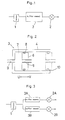
- reference numeral 1 designates an extraction furnace provided with a pair of electrodes for contacting an electrical AC heating of a crucible, in which for example a sample is housed.
- Reference numeral 2 designates a detector provided in an analytical portion, for example an infrared detector for detecting the concentration of oxygen.
- a buffer vessel 3 is disposed between the extraction furnace 1 and the detector 2, said buffer vessel 3 comprising a cylindrical stationary vessel 4 and a piston member 6 provided with a gas passage 5 and adapted to be slidable in directions of a double pointed arrow U - V.
- Reference numeral 8 designates a sealing member, such as an O-ring, provided around the periphery of the piston member 6.
- a gas passage 9 is formed in said chamber 7, and reference numeral 10 designates a gas-outlet toward the detector 2.
- the analysis can be carried out without interruption. That is to say, in the case where for example the concentration of the sample is actually higher even though the internal capacity of the chamber 7 is set to a small volume on the basis of the expected small concentration, the piston member 6 can be simply shifted in the direction of the arrow V to increase the internal capacity of the chamber 7, instantly adapting the analyzing device to the above described new and unexpected situation.
- the concentration ranges can be wide for the analysis of new materials, inconveniences that have occured in operating the prior analyzers, can satisfyingly be overcome with the invention.
- Fig. 3 shows another preferred embodiment of the present invention in which oxygen and nitrogen can be independently and simultaneously analyzed, respectively.
- reference numerals 3A, 3B designate a parallel arrangement of buffer vessels having the same construction as the buffer vessel 3 of Fig. 2.
- Detectors 2A, 2B are connected at the downstream side of the buffer vessels 3A, 3B, respectively.
- the detector 2A is an infra red ray detector for detecting oxygen and the detector 2B is a thermal conductivity type detector for detecting nitrogen.
- the sample analyzer having such a construction, in the case where the concentration of oxygen in the sample is high and that of nitrogen is low, or the case where the concentration of oxygen is low and that of nitrogen is high, or the case where both the concentrations of oxygen and that of nitrogen are high (or low), a specific analysis can be accurately carried out by appropriately setting the internal capacity of the chamber in the buffer vessels 3A, 3B, respectively.
- the content of oxygen in the sample is extremely different from the content of nitrogen in the same sample - for example, in the case where the sample is Si3N4, - the content of nitrogen is 30 to 50 wt% while the content of oxygen is only 0.01 to 5 wt%.
- an optimization of the buffer capacity is required for every ingredient to be measured, but the present invention can satisfyingly cope with such severe conditions.
- a specific analysis not only for low-concentration samples but also for high-concentration samples can be carried out within a short time without requiring a troublesome labour-intensive adjustment procedure as with the prior art analyzer.
- a continuous analysis is possible, so that the invention is well suited for mass analysis.
Landscapes
- Health & Medical Sciences (AREA)
- Life Sciences & Earth Sciences (AREA)
- Biochemistry (AREA)
- General Health & Medical Sciences (AREA)
- Molecular Biology (AREA)
- Physics & Mathematics (AREA)
- Chemical & Material Sciences (AREA)
- Analytical Chemistry (AREA)
- Engineering & Computer Science (AREA)
- Biomedical Technology (AREA)
- General Physics & Mathematics (AREA)
- Immunology (AREA)
- Pathology (AREA)
- Sampling And Sample Adjustment (AREA)
- Investigating Or Analyzing Non-Biological Materials By The Use Of Chemical Means (AREA)
- Investigating Or Analysing Materials By Optical Means (AREA)
- Investigating And Analyzing Materials By Characteristic Methods (AREA)
Applications Claiming Priority (2)
| Application Number | Priority Date | Filing Date | Title |
|---|---|---|---|
| JP1989002975U JPH084592Y2 (ja) | 1989-01-14 | 1989-01-14 | 試料分析装置 |
| JP2975/89U | 1989-01-14 |
Publications (3)
| Publication Number | Publication Date |
|---|---|
| EP0379090A2 true EP0379090A2 (de) | 1990-07-25 |
| EP0379090A3 EP0379090A3 (de) | 1991-04-03 |
| EP0379090B1 EP0379090B1 (de) | 1994-03-30 |
Family
ID=11544372
Family Applications (1)
| Application Number | Title | Priority Date | Filing Date |
|---|---|---|---|
| EP90100626A Expired - Lifetime EP0379090B1 (de) | 1989-01-14 | 1990-01-12 | Analysegerät für Gas aus einem Extraktionsofen |
Country Status (4)
| Country | Link |
|---|---|
| US (1) | US5024108A (de) |
| EP (1) | EP0379090B1 (de) |
| JP (1) | JPH084592Y2 (de) |
| DE (1) | DE69007629T2 (de) |
Family Cites Families (14)
| Publication number | Priority date | Publication date | Assignee | Title |
|---|---|---|---|---|
| DE839725C (de) * | 1952-04-10 | Dortmund Dipl.-Ing. Friedrich Wiebecke | Verfahren zur^Gewinnung einer Durchschnittsprobe von Gasen, z. G. Industriegasen | |
| US944247A (en) * | 1909-06-11 | 1909-12-21 | Joseph Smith | Apparatus for testing mine-gases. |
| DE1188836B (de) * | 1963-04-20 | 1965-03-11 | Huels Chemische Werke Ag | Vorrichtung zur Entnahme fluessiger Proben aus einem Strom verfluessigter Gase |
| FR1375183A (fr) * | 1963-08-28 | 1964-10-16 | Siderurgie Fse Inst Rech | Perfectionnements aux procédés de contrôle de processus industriels par analyse continue d'un mélange gazeux de composition variable |
| DE1598068C3 (de) * | 1965-08-17 | 1978-11-09 | Fried. Krupp Gmbh, 4300 Essen | Vorrichtung zur selbsttätigen fortlaufenden Probenahme von Abgasen |
| US3520657A (en) * | 1965-12-27 | 1970-07-14 | Dravo Corp | Method and apparatus for the analysis of off-gases in a refining process |
| DE2760375C2 (de) * | 1976-01-20 | 1990-11-29 | Institut Francais Du Petrole, Rueil-Malmaison, Hauts-De-Seine, Fr | |
| US4128008A (en) * | 1977-05-04 | 1978-12-05 | Xonics, Inc. | Concentration valve for a gas detecting apparatus, or the like |
| GB2052055A (en) * | 1979-07-02 | 1981-01-21 | British Steel Corp | Gas Sampling Apparatus |
| SU1041925A1 (ru) * | 1979-08-16 | 1983-09-15 | Специальное Конструкторское Бюро Газовой Хроматографии | Газовый хроматограф |
| US4298026A (en) * | 1979-12-17 | 1981-11-03 | Instrumentation Laboratory Inc. | Spool valve |
| JPS57171555U (de) * | 1981-04-22 | 1982-10-28 | ||
| US4676656A (en) * | 1985-01-25 | 1987-06-30 | Syntex (U.S.A.) Inc. | Fluid handling apparatus and method |
| JPS62138746A (ja) * | 1985-12-13 | 1987-06-22 | Toray Ind Inc | 酸素分析方法 |
-
1989
- 1989-01-14 JP JP1989002975U patent/JPH084592Y2/ja not_active Expired - Lifetime
- 1989-12-28 US US07/458,091 patent/US5024108A/en not_active Expired - Fee Related
-
1990
- 1990-01-12 DE DE69007629T patent/DE69007629T2/de not_active Expired - Fee Related
- 1990-01-12 EP EP90100626A patent/EP0379090B1/de not_active Expired - Lifetime
Also Published As
| Publication number | Publication date |
|---|---|
| JPH084592Y2 (ja) | 1996-02-07 |
| US5024108A (en) | 1991-06-18 |
| EP0379090A3 (de) | 1991-04-03 |
| DE69007629D1 (de) | 1994-05-05 |
| DE69007629T2 (de) | 1994-10-13 |
| EP0379090B1 (de) | 1994-03-30 |
| JPH0295834U (de) | 1990-07-31 |
Similar Documents
| Publication | Publication Date | Title |
|---|---|---|
| JPS55136958A (en) | Automatic analyzer | |
| EP2623951A2 (de) | Elementaranalysator | |
| AU2613400A (en) | Detection of base contaminants in gas samples | |
| EP0238054A2 (de) | Vorrichtung zur Analyse eines Gases in einer Metallschmelze | |
| WO2002048678A3 (en) | High capacity and scanning speed system for sample handling and analysis | |
| CA2019571A1 (en) | Method and Apparatus for Gas Analysis | |
| RU2273847C2 (ru) | Способ измерения общей концентрации окиси углерода и углеводородов в кислороде с помощью спектрометрии подвижности ионов | |
| EP0379090A2 (de) | Analysegerät für Gas aus einem Extraktionsofen | |
| Lorber et al. | Convenient method for the determination of trace elements in solid samples using an inductively coupled plasma | |
| Duffy et al. | Benefits of a dual-view ICP-OES for the determination of boron, phosphorus, and sulfur in low alloy steels | |
| EP0890839A2 (de) | Verfahren zur analytischen Feststellung von Sauerstoff für jede Oxidform | |
| EP0453190A2 (de) | Verfahren zum Messen des Kohlenmonoxidgehaltes eines Gases | |
| Siemens et al. | Applicability of microwave induced plasma optical emission spectrometry (MIP-OES) for continuous monitoring of mercury in flue gases | |
| JP3215243B2 (ja) | 油中ガス分析装置 | |
| Tilden et al. | A comparison of data reduction techniques for line-excited optoacoustic analysis of mixtures | |
| JP3439974B2 (ja) | 分析試料中の酸化物の種類別酸素又は酸化物の分析方法及び分析装置 | |
| JPS5829575B2 (ja) | ガス分析装置 | |
| Paque | Vanadium-rich refractory platinum metal nuggets from a fluffy Type A inclusion in Allende | |
| Fujimoto et al. | Investigation of direct sample insertion and tungsten filament electrothermal vaporization for micro sample analysis by ICP-AES | |
| LaMothe et al. | Analysis of Carbon Gradients by Microsound | |
| Shigeta et al. | Vacuum fusion determination of oxygen in gadolinium, terbium metal and iron-terbium alloy | |
| Wikblad | Sampling gas with diaphragm pumps. | |
| Hershenhart et al. | Improving productivity with automated surface area measurements. | |
| Pan | Rapid Determination of Components in Brake Block | |
| Bovin | High resolution transmission electron microscopy (HRTEM)--An important method in solid state chemistry |
Legal Events
| Date | Code | Title | Description |
|---|---|---|---|
| PUAI | Public reference made under article 153(3) epc to a published international application that has entered the european phase |
Free format text: ORIGINAL CODE: 0009012 |
|
| AK | Designated contracting states |
Kind code of ref document: A2 Designated state(s): DE GB |
|
| PUAL | Search report despatched |
Free format text: ORIGINAL CODE: 0009013 |
|
| AK | Designated contracting states |
Kind code of ref document: A3 Designated state(s): DE GB |
|
| 17P | Request for examination filed |
Effective date: 19910923 |
|
| 17Q | First examination report despatched |
Effective date: 19930512 |
|
| GRAA | (expected) grant |
Free format text: ORIGINAL CODE: 0009210 |
|
| AK | Designated contracting states |
Kind code of ref document: B1 Designated state(s): DE GB |
|
| REF | Corresponds to: |
Ref document number: 69007629 Country of ref document: DE Date of ref document: 19940505 |
|
| PG25 | Lapsed in a contracting state [announced via postgrant information from national office to epo] |
Ref country code: GB Effective date: 19950112 |
|
| PLBE | No opposition filed within time limit |
Free format text: ORIGINAL CODE: 0009261 |
|
| STAA | Information on the status of an ep patent application or granted ep patent |
Free format text: STATUS: NO OPPOSITION FILED WITHIN TIME LIMIT |
|
| 26N | No opposition filed | ||
| GBPC | Gb: european patent ceased through non-payment of renewal fee |
Effective date: 19950112 |
|
| PG25 | Lapsed in a contracting state [announced via postgrant information from national office to epo] |
Ref country code: DE Effective date: 19951003 |