EP0380320B1 - Optisches Abtastgerät - Google Patents
Optisches Abtastgerät Download PDFInfo
- Publication number
- EP0380320B1 EP0380320B1 EP90300741A EP90300741A EP0380320B1 EP 0380320 B1 EP0380320 B1 EP 0380320B1 EP 90300741 A EP90300741 A EP 90300741A EP 90300741 A EP90300741 A EP 90300741A EP 0380320 B1 EP0380320 B1 EP 0380320B1
- Authority
- EP
- European Patent Office
- Prior art keywords
- pickup apparatus
- optical pickup
- side portions
- order diffracted
- zero
- Prior art date
- Legal status (The legal status is an assumption and is not a legal conclusion. Google has not performed a legal analysis and makes no representation as to the accuracy of the status listed.)
- Expired - Lifetime
Links
Images



Classifications
-
- G—PHYSICS
- G11—INFORMATION STORAGE
- G11B—INFORMATION STORAGE BASED ON RELATIVE MOVEMENT BETWEEN RECORD CARRIER AND TRANSDUCER
- G11B7/00—Recording or reproducing by optical means, e.g. recording using a thermal beam of optical radiation by modifying optical properties or the physical structure, reproducing using an optical beam at lower power by sensing optical properties; Record carriers therefor
- G11B7/12—Heads, e.g. forming of the optical beam spot or modulation of the optical beam
- G11B7/135—Means for guiding the beam from the source to the record carrier or from the record carrier to the detector
- G11B7/1353—Diffractive elements, e.g. holograms or gratings
-
- G—PHYSICS
- G11—INFORMATION STORAGE
- G11B—INFORMATION STORAGE BASED ON RELATIVE MOVEMENT BETWEEN RECORD CARRIER AND TRANSDUCER
- G11B7/00—Recording or reproducing by optical means, e.g. recording using a thermal beam of optical radiation by modifying optical properties or the physical structure, reproducing using an optical beam at lower power by sensing optical properties; Record carriers therefor
- G11B7/12—Heads, e.g. forming of the optical beam spot or modulation of the optical beam
- G11B7/123—Integrated head arrangements, e.g. with source and detectors mounted on the same substrate
Definitions
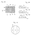
- the laser light spot is indicated by a circle L .
- the distribution of the laser beam intensity entering the objective lens 25 can be adjusted so that a laser beam of high intensity is obtained at the center of the spot S while reducing the laser beam intensity at the periphery thereof. This results in a weakened intensity of the Airy ring of the laser spot S , thereby hindering the occurrence of crosstalk even in the case of a narrow recording track width.
- the diffraction grating 2 is made of glass (having a refractive index of 1.52).
- the grating pattern formed on the surface 2a of the diffraction grating 2 has narrow-width grooves 11a and wide-width grooves 11b .
- the narrow-width grooves 11a are positioned at the center portion a , and the wide-width grooves 11b at the side portions b which sandwich the center portion a ( Figure 4).
- the center portion a has a rectangular shape in plan view which elongates in the direction of the tracks of the optical disk 6 , and is positioned so as to correspond with the track from which information is to be read out.
- the zero-order beam diffraction efficiency ⁇ 0A through the center portion a is greater than the zero-order beam diffraction efficiency ⁇ 0B through the side portions b .
- the main beam (a zero-order diffracted beam which has been diffracted by the grating pattern 13 ) is diffracted by the region 14b of the hologram pattern 14 so as to be converged on the boundary between the light receiving elements 15a and 15b , thereby forming a spot thereon, while the main beam is diffracted by the region 14a so as to be converged on the light receiving element 15c , thereby forming a spot thereon.
- the two sub beams diffracted by the hologram pattern 14 (plus and minus first-order diffracted beam which has been diffracted by the grating pattern 13 ) are converged on the light receiving elements 15d and 15e to form respective spots.
Landscapes
- Physics & Mathematics (AREA)
- Optics & Photonics (AREA)
- Optical Head (AREA)
- Diffracting Gratings Or Hologram Optical Elements (AREA)
- Optical Recording Or Reproduction (AREA)
Claims (6)
- Optisches Abtastgerät mit einer Lichtquelle (1) und einer optischen Einrichtung (2) mit einem Gittermuster zum Aufteilen eines Lichtstrahls von der Lichtquelle in einen gebeugten Strahl der Ordnung Null und in gebeugte Strahlen der Ordnungen Plus-Eins und Minus-Eins,
wobei das Gittermuster einen Mittelbereich (a) und einen oder mehrere Seitenbereiche (b) aufweist und die Effektivität des Mittelbereichs für den gebeugten Strahl der Ordnung Null größer ist, als die Effektivität der Seitenbereiche für den gebeugten Strahl der Ordnung Null,
dadurch gekennzeichnet, daß das Verhältnis der Effektivität der Seitenbereiche für den gebeugten Strahl der Ordnung Null zu der Effektivität des Mittelbereichs für den gebeugten Strahl der Ordnung Null 0,34 beträgt. und daß
das Verhältnis (RS) der Fläche (SA) des auf den Mittelbereich (a) einfallenden Lichtstrahls zu der Fläche (SB) des auf den oder die Seitenbereiche (b) einfallenden Lichtstrahls 1,13 beträgt. - Optisches Abtastgerät nach Anspruch 1, dadurch gekennzeichnet, daß der Mittelbereich (a) von den Seitenbereichen (b) umgeben ist.
- Optisches Abtastgerät nach Anspruch 1 oder 2, dadurch gekennzeichnet, daß das Nutzverhältnis der Gitter in dem Mittelbereich (a) kleiner ist als das der Seitenbereiche (b).
- Optisches Abtastgerät nach Anspruch 1 oder 2, dadurch gekennzeichnet, daß das Nutzverhältnis der Gitter in dem Mittelbereich (a) größer ist als das der Seitenbereiche (b).
- Optisches Abtastgerät nach Anspruch 1, dadurch gekennzeichnet, daß die drei Strahlen zum Fokussieren auf ein Informationen aufnehmendes Medium mit Aufzeichnungsspuren dienen, um dadurch die in den Aufzeichnungsspuren gespeicherten Informationen abzutasten, und daß der Mittelbereich (a) in der der Richtung der Aufzeichnungsspuren entsprechenden Richtung langgestreckt ist.
- Optisches Abtastgerät nach Anspruch 1, dadurch gekennzeichnet, daß das Gittermuster (13) auf einer Oberfläche der optischen Einrichtung ausgebildet ist, und daß die optische Einrichtung ein auf der der einen Oberfläche gegenüberstehenden anderen Oberfläche ausgebildetes Hologrammuster (14) zum Aufteilen eines von außen einfallenden Lichtstrahls aufweist.
Applications Claiming Priority (2)
| Application Number | Priority Date | Filing Date | Title |
|---|---|---|---|
| JP18022/89 | 1989-01-27 | ||
| JP1018022A JPH0778904B2 (ja) | 1989-01-27 | 1989-01-27 | 光ピックアップ装置 |
Publications (3)
| Publication Number | Publication Date |
|---|---|
| EP0380320A2 EP0380320A2 (de) | 1990-08-01 |
| EP0380320A3 EP0380320A3 (de) | 1991-06-26 |
| EP0380320B1 true EP0380320B1 (de) | 1995-11-02 |
Family
ID=11960041
Family Applications (1)
| Application Number | Title | Priority Date | Filing Date |
|---|---|---|---|
| EP90300741A Expired - Lifetime EP0380320B1 (de) | 1989-01-27 | 1990-01-24 | Optisches Abtastgerät |
Country Status (6)
| Country | Link |
|---|---|
| US (1) | US5410529A (de) |
| EP (1) | EP0380320B1 (de) |
| JP (1) | JPH0778904B2 (de) |
| KR (1) | KR930003869B1 (de) |
| CA (1) | CA2008593C (de) |
| DE (1) | DE69023252T2 (de) |
Families Citing this family (13)
| Publication number | Priority date | Publication date | Assignee | Title |
|---|---|---|---|---|
| JP2617237B2 (ja) * | 1990-08-28 | 1997-06-04 | シャープ株式会社 | 光スポット位置検出装置 |
| JPH06309685A (ja) * | 1993-04-26 | 1994-11-04 | Nippon Conlux Co Ltd | 光学式情報記録再生装置のレーザ出力制御装置 |
| US5694385A (en) * | 1993-09-24 | 1997-12-02 | Ricoh Comany, Ltd. | Optical pickup apparatus |
| KR970010940B1 (ko) * | 1994-04-08 | 1997-07-02 | 엘지전자 주식회사 | 광픽업장치 |
| JPH07311961A (ja) * | 1994-05-16 | 1995-11-28 | Nippon Steel Corp | 光ピックアップ |
| JPH0845107A (ja) * | 1994-08-01 | 1996-02-16 | Oki Electric Ind Co Ltd | 光記録・再生装置および情報記録用の媒体 |
| US5523993A (en) * | 1995-05-17 | 1996-06-04 | Opto-Electronics & Systems Laboratories | Holographic optical element for optical disk pickup head |
| JP2751884B2 (ja) * | 1995-08-15 | 1998-05-18 | 日本電気株式会社 | 光ヘッド装置 |
| WO1997023871A1 (en) * | 1995-12-21 | 1997-07-03 | Philips Electronics N.V. | Optical scanning device |
| JPH11213441A (ja) * | 1998-01-23 | 1999-08-06 | Rohm Co Ltd | 光ピックアップおよびその調整方法 |
| JPH11223729A (ja) * | 1998-02-09 | 1999-08-17 | Sankyo Seiki Mfg Co Ltd | 偏光分離素子およびその製造方法 |
| JP2003248960A (ja) * | 2002-02-25 | 2003-09-05 | Sony Corp | 光学ピックアップ及びディスクドライブ装置 |
| JP2009140551A (ja) * | 2007-12-05 | 2009-06-25 | Sony Corp | 光学ピックアップおよび光ディスクドライブ |
Citations (1)
| Publication number | Priority date | Publication date | Assignee | Title |
|---|---|---|---|---|
| EP0123048A1 (de) * | 1983-02-28 | 1984-10-31 | International Business Machines Corporation | Lesekopf mit Hologrammoptik |
Family Cites Families (10)
| Publication number | Priority date | Publication date | Assignee | Title |
|---|---|---|---|---|
| JPS6124033A (ja) * | 1984-07-13 | 1986-02-01 | Sony Corp | 光学式ヘツドのトラツキング誤差検出装置 |
| JPS62103857A (ja) * | 1985-10-31 | 1987-05-14 | Mitsubishi Electric Corp | 光ピツクアツプ装置 |
| DE3679648D1 (de) * | 1985-12-10 | 1991-07-11 | Nec Corp | Optischer kopf mit einem beugungsgitter zum richten von zwei oder mehreren gebeugten lichtstrahlen auf optische detektoren. |
| JPS62212940A (ja) * | 1986-03-12 | 1987-09-18 | Fujitsu Ltd | 光ピツクアツプ |
| JPS62236147A (ja) * | 1986-04-07 | 1987-10-16 | Mitsubishi Electric Corp | 光学式情報再生装置 |
| JPS62270034A (ja) * | 1986-05-19 | 1987-11-24 | Sony Corp | 光学式再生装置 |
| DE3786497T2 (de) * | 1986-07-18 | 1994-02-17 | Nippon Electric Co | Doppelbrechendes Beugungsgitter und optischer Kopf, in welchem ein linearpolarisierter Strahl auf dieses Gitter gelenkt wird. |
| JPS63222340A (ja) * | 1987-03-12 | 1988-09-16 | Matsushita Electric Ind Co Ltd | 光ピツクアツプ |
| JPS63222341A (ja) * | 1987-03-12 | 1988-09-16 | Matsushita Electric Ind Co Ltd | 光ピツクアツプ |
| US4907847A (en) * | 1987-09-28 | 1990-03-13 | Nec Home Electronics Ltd. | Optical pickup and hologram therefor |
-
1989
- 1989-01-27 JP JP1018022A patent/JPH0778904B2/ja not_active Expired - Lifetime
-
1990
- 1990-01-24 EP EP90300741A patent/EP0380320B1/de not_active Expired - Lifetime
- 1990-01-24 DE DE69023252T patent/DE69023252T2/de not_active Expired - Lifetime
- 1990-01-24 KR KR1019900000784A patent/KR930003869B1/ko not_active Expired - Lifetime
- 1990-01-25 CA CA002008593A patent/CA2008593C/en not_active Expired - Lifetime
-
1993
- 1993-03-01 US US08/026,177 patent/US5410529A/en not_active Expired - Lifetime
Patent Citations (1)
| Publication number | Priority date | Publication date | Assignee | Title |
|---|---|---|---|---|
| EP0123048A1 (de) * | 1983-02-28 | 1984-10-31 | International Business Machines Corporation | Lesekopf mit Hologrammoptik |
Also Published As
| Publication number | Publication date |
|---|---|
| JPH02199634A (ja) | 1990-08-08 |
| EP0380320A2 (de) | 1990-08-01 |
| US5410529A (en) | 1995-04-25 |
| CA2008593A1 (en) | 1990-07-27 |
| EP0380320A3 (de) | 1991-06-26 |
| DE69023252T2 (de) | 1996-07-04 |
| KR900012222A (ko) | 1990-08-03 |
| DE69023252D1 (de) | 1995-12-07 |
| JPH0778904B2 (ja) | 1995-08-23 |
| KR930003869B1 (ko) | 1993-05-14 |
| CA2008593C (en) | 1994-10-04 |
Similar Documents
| Publication | Publication Date | Title |
|---|---|---|
| JP3507632B2 (ja) | 回折格子レンズ | |
| EP0354019B1 (de) | Optische Kopfanordnung zum Lesen von in einem Aufzeichnungsmedium gespeicherten Informationen | |
| US7072272B2 (en) | Diffraction type optical pickup lens and optical pickup apparatus using the same | |
| US6778475B2 (en) | Optical detector, optical pickup and optical information reproducing apparatus using optical pickup for detecting at least three light beams separated from one or more light sources | |
| US5400311A (en) | Hologram and optical apparatus with hologram | |
| KR19980087503A (ko) | 광 헤드 장치 | |
| EP0380320B1 (de) | Optisches Abtastgerät | |
| US5436876A (en) | Optical head and optical memory device | |
| JPH09180245A (ja) | 異なる厚さを有するディスクと互換が可能な記録再生用の光ピックアップ | |
| KR20020008795A (ko) | 호환형 광픽업장치 | |
| JPH0775080B2 (ja) | 光学式走査装置 | |
| EP0426248B1 (de) | Rasterobjektiv und Raster-Strahlumformer sowie optische Abtastvorrichtung mit zumindest einem dieser Elemente | |
| JP2801176B2 (ja) | 対物レンズ及びそれを具備した光ピックアップ装置 | |
| JPH11174218A (ja) | 回折型フィルタ | |
| JPH0630164B2 (ja) | 光ヘツド装置 | |
| JP2877044B2 (ja) | 光ヘッド装置 | |
| JP3455399B2 (ja) | 光ディスク用センサシステム | |
| JP3261794B2 (ja) | 光ヘッド | |
| JPH0687311B2 (ja) | 光学式情報再生装置 | |
| JP2641258B2 (ja) | 光学式ヘッド装置 | |
| KR100644588B1 (ko) | 고밀도 기록 재생 가능한 광픽업장치 | |
| JPH06347693A (ja) | 回折格子一体型のレンズとそれを用いた光ヘッド装置 | |
| JP3455398B2 (ja) | 光ディスク用センサシステム | |
| JPH05307760A (ja) | 光ピックアップ | |
| JPH06203406A (ja) | 高密度記録デ−タを読みとり可能な光学ヘッド装置 |
Legal Events
| Date | Code | Title | Description |
|---|---|---|---|
| PUAI | Public reference made under article 153(3) epc to a published international application that has entered the european phase |
Free format text: ORIGINAL CODE: 0009012 |
|
| 17P | Request for examination filed |
Effective date: 19900203 |
|
| AK | Designated contracting states |
Kind code of ref document: A2 Designated state(s): DE FR GB IT NL |
|
| PUAL | Search report despatched |
Free format text: ORIGINAL CODE: 0009013 |
|
| AK | Designated contracting states |
Kind code of ref document: A3 Designated state(s): DE FR GB IT NL |
|
| 17Q | First examination report despatched |
Effective date: 19930616 |
|
| GRAA | (expected) grant |
Free format text: ORIGINAL CODE: 0009210 |
|
| AK | Designated contracting states |
Kind code of ref document: B1 Designated state(s): DE FR GB IT NL |
|
| ITF | It: translation for a ep patent filed | ||
| REF | Corresponds to: |
Ref document number: 69023252 Country of ref document: DE Date of ref document: 19951207 |
|
| ET | Fr: translation filed | ||
| PLBE | No opposition filed within time limit |
Free format text: ORIGINAL CODE: 0009261 |
|
| 26N | No opposition filed | ||
| REG | Reference to a national code |
Ref country code: GB Ref legal event code: IF02 |
|
| PGFP | Annual fee paid to national office [announced via postgrant information from national office to epo] |
Ref country code: NL Payment date: 20090115 Year of fee payment: 20 Ref country code: DE Payment date: 20090123 Year of fee payment: 20 |
|
| PGFP | Annual fee paid to national office [announced via postgrant information from national office to epo] |
Ref country code: GB Payment date: 20090121 Year of fee payment: 20 |
|
| PGFP | Annual fee paid to national office [announced via postgrant information from national office to epo] |
Ref country code: IT Payment date: 20090127 Year of fee payment: 20 |
|
| PGFP | Annual fee paid to national office [announced via postgrant information from national office to epo] |
Ref country code: FR Payment date: 20090113 Year of fee payment: 20 |
|
| REG | Reference to a national code |
Ref country code: GB Ref legal event code: PE20 Expiry date: 20100123 |
|
| NLV7 | Nl: ceased due to reaching the maximum lifetime of a patent |
Effective date: 20100124 |
|
| PG25 | Lapsed in a contracting state [announced via postgrant information from national office to epo] |
Ref country code: GB Free format text: LAPSE BECAUSE OF EXPIRATION OF PROTECTION Effective date: 20100123 |
|
| PG25 | Lapsed in a contracting state [announced via postgrant information from national office to epo] |
Ref country code: NL Free format text: LAPSE BECAUSE OF EXPIRATION OF PROTECTION Effective date: 20100124 |
|
| PG25 | Lapsed in a contracting state [announced via postgrant information from national office to epo] |
Ref country code: DE Free format text: LAPSE BECAUSE OF EXPIRATION OF PROTECTION Effective date: 20100124 |