EP0380371B1 - Dispositif de commande à distance avec mémoire - Google Patents
Dispositif de commande à distance avec mémoire Download PDFInfo
- Publication number
- EP0380371B1 EP0380371B1 EP90300862A EP90300862A EP0380371B1 EP 0380371 B1 EP0380371 B1 EP 0380371B1 EP 90300862 A EP90300862 A EP 90300862A EP 90300862 A EP90300862 A EP 90300862A EP 0380371 B1 EP0380371 B1 EP 0380371B1
- Authority
- EP
- European Patent Office
- Prior art keywords
- remote
- control signal
- category data
- key
- signal
- Prior art date
- Legal status (The legal status is an assumption and is not a legal conclusion. Google has not performed a legal analysis and makes no representation as to the accuracy of the status listed.)
- Expired - Lifetime
Links
Images





Classifications
-
- G—PHYSICS
- G06—COMPUTING OR CALCULATING; COUNTING
- G06F—ELECTRIC DIGITAL DATA PROCESSING
- G06F12/00—Accessing, addressing or allocating within memory systems or architectures
-
- G—PHYSICS
- G08—SIGNALLING
- G08C—TRANSMISSION SYSTEMS FOR MEASURED VALUES, CONTROL OR SIMILAR SIGNALS
- G08C19/00—Electric signal transmission systems
- G08C19/16—Electric signal transmission systems in which transmission is by pulses
- G08C19/28—Electric signal transmission systems in which transmission is by pulses using pulse code
Definitions
- the present invention relates to a learning remote control device, a so-called “memory remote control", having a learning capability in which a remote-control signal can be stored in a memory after such remote-control signal has been received and analyzed and can be reproduced for transmission on the basis of data stored in the memory.
- the invention also relates to a method of storing commands in such a device.
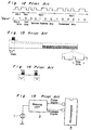
- the pulse signal having a predetermined pulse width as shown in Fig. 17(D) is outputted on the basis of the set-up timing of the received remote-controlled signal shown in Fig. 17(C) and the envelope signal shown in Fig. 17(E) is also outputted which envelope signal sets up in synchronism with the set-up timing of the pulse signal and sets down when the pulse signal is not present during a predetermined period ⁇ .
- US 4,626,848 discloses a reconfigurable (i.e. learning) remote control device in which a coded signal to be learnt is sent at least twice from a remote controller to be emulated in order to make sure that it has been properly received and decoded.
- the received signal is a succession of signal portions comprising pulse bursts and pauses, and on each reception each such signal portion is categorised according to whether it is a pulse burst or a pause and according to the number of pulses in the burst and the duration in the pause.
- the categorisation codes for the successively received coded signals are compared in accordance with a correlation algorithm until a match of alternate encodings is established.
- a method of storing commands in a learning remote control device comprising the steps of:
- the microcomputer 3 includes an input port 4 to which the remote-control signal received by the photodiode 1 is supplied directly; a determining means for determining whether or not the received remote-control signal is a remote-control signal having no carrier wave utilizing the unique logic, that is, a remote-control signal of particular format, on the basis of a pulse signal and an envelope signal both outputted from the wave shaping circuit 2; a storing means operable to convert the remote-control signal into data and storing such data in the memory on the basis of the remote-control signal inputted to the input port 4 in the event that the determining means indicates that the received remote-control signal is the remote-control signal of particular format; and a reproducing means for reproducing the remote-control signal of particular format on the basis of the data stored in the memory.
- the wave shaping circuit having the one-shot circuit built therein outputs the pulse signal of predetermined pulse width as shown in Fig. 2(C) on the basis of the set-up of the remote-control signal received as shown in Fig. 2(B) and, also, the envelope signal which sets up in synchronism with the set-up of the pulse signal and sets down in the event that the pulse signal is not present during a predetermined period.
- step S2 takes place at which a decision is made to determine if there is one pulse signal during a high level period of the envelope signal.
- step S2 Should the result of decision at step S2 indicate that the number of the pulse signals present during the high level period of the envelope signal is not one, that is, there is a plurality of pulse signals, it means that the received remote-control signal is not a remote-control signal of the particular format but is a remote-control signal having the carrier wave and, therefore, the program flow proceeds to step S5 at which a normal storing operation as in the case with the prior art takes place to store in the memory such data as the frequency of the carrier wave obtained on the basis of the pulse signal and the envelope signal, with the program flow subsequently terminating.
- the data are prepared on the basis of the remote-control signal inputted directly to the input port 4 of the microcomputer 3 and are then stored in the memory.
- the remote-control signal is made to set down sequentially before each of the low level periods T1, T2, T1, T3, ... stored in the memory from the timing at which the remote-control signal is subsequently set up.
- the remote-control signal is made to set down sequentially after a predetermined period ⁇ subsequent to the set-up of the remote-control signal
- the set-down of the remote-controlled signal in the device now under discussion is sequentially made before each of the low level periods T1, T2, T1, T3, ..., stored in the memory from the timing at which the remote-control signal subsequently sets up.
- the reproduced remote-control signal corresponds faithfully to the received remote-control signal of the waveform of Fig. 2(B) and, therefore, unlike the prior art system of Fig. 18, the set-down of the received signal can also be reproduced accurately.
- the remote-control signal of the particular format since in the event of the remote-control signal of the particular format the remote-control signal is directly analyzed and converted into the data before it is stored in the memory and, on the basis of the data stored in the memory, the remote-control signal is subsequently reproduced, the remote-control signal of the particular format which has hitherto been unable to be reproduced according to the prior art system wherein the remote-control signal is converted into the data on the basis of only the envelope and pulse signals can be advantageously faithfully reproduced.
- Figures 4 to 6 illustrate another device proposed by the inventors and now to be described by way of background information.
- This device is not in accordance with the present invention, though it is concerned with a problem which is allied to that addressed by the present invention and which also arises in the case that the remote-control signal received from the to-be-learned remote control device is of the type wherein the code of a particular bit or bits changes each time the same key is manipulated.
- reference numeral 11 represents a receiving circuit for receiving an infrared remote-control signal emitted from a to-be-learned remote control device (not shown) and for outputting it to a microcomputer 15 after the waveform thereof has been shaped;
- reference numeral 12 represents a key input unit;
- reference numeral 13 represents a reset circuit;
- reference numeral 14 represents a static random access memory (S-RAM) for the storage of data processed by the microcomputer 15;
- reference numeral 16 represents a memory control circuit for controlling writing and reading operations relative to the static random access memory 14;
- reference numerals 17 and 18 represent a buzzer and a LED (light emitting diode) display for providing an operator with audio and visual indications as to operating procedures when the remote-control signal from the to-be-learned remote control device is to be stored in a manner as will be described later, respectively; and
- reference numeral 19 represents a transmitting circuit, including a light emitting diode and a drive circuit there
- the receiving circuit 11 When, for example, the remote-control signal of the waveform shown in Fig. 5(A) is inputted to the receiving circuit 11, the receiving circuit 11 outputs to the microcomputer 15 both of a pulse signal of the waveform of Fig. 5(B), which is an output from a mono-stable multivibrator triggered in response to a set-up edge of the inputted signal, and an envelope signal of the waveform of Fig. 5(C) which, in the event that the interval of the pulse signal expands to a value larger than a predetermined period ⁇ , sets down after the predetermined period ⁇ subsequent to the set-up edge of the final pulse of the continuous pulse signal and sets up in response to a set-up edge of the next succeeding pulse signal.
- a pulse signal of the waveform of Fig. 5(B) which is an output from a mono-stable multivibrator triggered in response to a set-up edge of the inputted signal
- an envelope signal of the waveform of Fig. 5(C) which
- the learning remote control device In order for the learning remote control device to be able to learn not only all forths of the remote-control signal, in which the code of particular bit varies each time a key is manipulated, such as generally utilized in some European countries, but also the usual remote-control signal in which there is no such code variation, the learning remote control device now under discussion is so designed as follows.
- the learning remote control device comprises a determining means operable, during a storing mode and in the event that a remote-control signal received in correspondence with a first key manipulation of the to-be-learned remote control device and a remote-control signal received in correspondence with a second key manipulation thereof does not coincide with each other, to refer to respective codes of these two remote-control signals to determine whether or not it is a remote-control signal of a format wherein the code of a particular bit varies each time the key is operated, so that, in the event that the received remote-control signal is a remote-control signal of the format wherein the code of particular bit varies, the remote-control signal corresponding to such format can be stored in the static random access memory 14.
- an infrared light emitting window of the to-be-learned remote control device and an infrared light receiving window of the learning remote control device now under discussion are to be positioned in face-to-face relationship so that the remote-control signal in the form of an infrared light can be inputted from the to-be-learned remote control device to the learning remote control device before the storing operation is initiated.
- a first remote-control signal A is inputted at step m4 and, after this remote-control signal A has been converted into a data, two electronic beeps are generated along with the lighting of a light emitting diode (LED) at step m5 to indicate that the first process has been completed and the next succeeding input operation is invited. Then, the manipulation of the key of both of the to-be-learned remote control device and that of the learning remote control device is released for the time to come at step m6.
- LED light emitting diode
- the first and second remote-control signals A and B are compared to determine if they coincide with each other. If they coincide with each other, it means that the remote-control signal is of a type wherein no code of a particular bit varies each time the key is manipulated, that is, the generally utilized remote-control signal, and therefore, the remote-control signal B is stored at step mll, followed by step m12 at which a single electronic beep is generated along with the lighting of a light emitting diode to indicate that the storage has been completed, thereby releasing the key manipulation at step m13.
- first and second remote-control signals A and B do not coincide with each other as determined at step m10
- respective codes of these first and second remote-control signals A and B are referred to and a respective decision is made successively at step m14 and m15 to determine if the remote-control signal is of a type wherein the code of particular one bit varies or of a type wherein the code of particular two bits varies.
- both of the first and second remote-control signals A and B are stored at step m16, followed by step m12 at which the electronic beep is generated along with the lighting of the light emitting diode to indicate that the storage has been completed, thereby releasing the key manipulation at step m13.
- the remote-control signal is of the type wherein the code of particular two bits varies as determined at step ml5
- two electronic beeps are generated along with the lighting of a light emitting diode at step m17 to invite that the input operation is to be repeated.
- an electronic beep can be outputted at step m20 to indicate that the learning remote control device is in a position ready to receive the remote-control signal.
- a third remote-control signal C can be inputted at step m21.
- the remote-control signal of the type wherein the particular two bits vary is such that, as hereinbefore described, the first and second bits of the remote-control signal vary regularly in a manner of 00, 01, 10, 11, 00, 01, 10, 11, 00, ..., the remote-control signal D to be outputted the fourth time can be readily determined from the first to third remote-control signals so received and, therefore, the remote-control signal D to be outputted the fourth time is prepared.
- the remote-control signal D so prepared and the first to third remote-control signals A, B and C are then stored at step m 24, followed by step m12 at which the electronic beep is generated along with the lighting of the light emitting diode to indicate that the storage has been completed, thereby releasing the key manipulation at step m13.
- the remote-control signal received in correspondence with the first manipulation of the key of the to-be-learned remote control device and the remote-control signal received in correspondence with the second manipulation of the key of the to-be-learned remote control device are compared and, in the event that the both coincide with each other, the remote-control signals thereof are stored as is the case with that occurring in the prior art system, but in the event that the both do not coincide with each other, the respective codes of those remote-control signals are referred to so that the decision can be made to determine if they are of the type wherein the code of a particular bit varies each time the key is manipulated. If they are of such type, the remote-control signal corresponding to such type is stored. Accordingly, not only can the generally used remote-control signal be stored as is the case with the prior art system, but the remote-control signal of the type wherein the code of particular bit varies, such as employed in some European countries, can also be stored.
- the remote-control signal once stored can be reproduced and transmitted in a manner similar to those in the prior art system.
- the remote-control signal wherein the code of particular bit varies
- the remote-control signal wherein the code of particular bit varies is reproduced and transmitted each time the key is manipulated.
- the remote-controlled signals A and B are alternately transmitted each time the key is manipulated, but with the remote-control signal of the type wherein the code of particular two bits varies, the remote-controlled signals A, B, C and D are successively and cyclically transmitted each time the key is manipulated.
- the first received remote-control signal from the to-be-learned remote control device and the second received remote-control signal are compared and, in the event that the both coincide with each other, the remote-control signals thereof are stored as is the case with that occurring in the prior art system, but in the event that they do not coincide with each other, the respective codes of those remote-control signals are referred to so that the decision can be made to determine if they are of the type wherein the code of particular bit varies each time the key is manipulated. If they are of such type, the remote-control signal corresponding to such type is stored. Accordingly, it is possible to learn not only the generally used remote-controlled signal but also the remote-control signal of the type wherein the code of particular bit varies.
- the learning remote control device according to a preferred embodiment of the present invention which will now be described and the waveforms of various signals used to explain the operation thereof are identical with those shown in Figs. 4 and 5 in connection with the previously described device respectively. Accordingly, for the sake of brevity, such details of the learning remote control device according to the preferred embodiment of the present invention and the operation thereof will not be reiterated.
- the storing mode executed by the learning remote control device is performed in a manner as shown in the flowchart shown in Fig. 11 which will be described later.
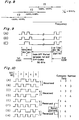
- the learning remote control device according to the preferred embodiment of the present invention is so designed as to generate a so-called RC-5 remote-control signal such as employed in some European countries, that is, the remote-control signal of a type wherein one particular bit varies each time the remote control device is manipulated, namely, of a type wherein the third bit from the beginning of the remote control code varies in such a manner, 0, 1, 0, 1, ..., each time the key is manipulated.
- the set-up at the center of each bit and the set-down at the center of each bit correspond respectively to logic levels of "1" and "0".
- the first two bits that is, the start bits
- the next succeeding control bit which is called “reversed bit”
- the reversed bit is of a type which may reverse in logic level state between "0" and "1" each time the same key in a remote-controlling transmitter is manipulated.
- the learning remote control device In order for the remote-control signal of the type wherein the code of a particular bit reverses each time the key is manipulated as hereinbefore described, that is, the so-called RC-5 signal, to be learned, the learning remote control device according to the preferred embodiment is so designed as follows.
- the RC-5 signal shown in Fig. 12 is categorized into a plurality of category data for two or three bits so that it can be stored as a category number data (number of the category).
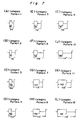
- category data are understood in the form as patterned and are basically available in four kinds as shown in Figs. 7(A) to 7(D), and the 14-bit remote-control signal shown in Fig. 12 can be recognized as a combination of the four category patterns 1 to 4.
- Each of the four category patterns 1 to 4 can be defined by the previously described period t1 (the period from the initial set-up timing to the next succeeding set-up timing of the envelope signal) and the pulse number N (the number of pulse signals present within the period t1).
- the four category patterns 1 to 4 shown in Figs. 7(A) to 7(D), respectively, have their pulse number N and period t1 indicated by N1, t1a; N1, t1b; N2, t1b; and N2, t1c, respectively.
- the pulse numbers N1 and N2 are 32 and 64, respectively, and each of the periods t1a, t1b and t1c is a period defined in correspondence with the carrier frequency of the remote-control signal.
- the above described category patterns 1 to 4 correspond to the carrier frequency f1 shown in Fig. 8; the category patterns 5 to 8 correspond to the carrier frequency f2 shown in Fig. 8; and the category patterns 9 to 12 correspond to the carrier frequency f3.
- the RC-5 signal of the carrier frequency shown in Fig. 8 can be recognized as a combination of the four category patterns of any one of the three carrier frequency groups depending on particular respective values of the period tl and the pulse number N possessed by the remote-control signal.
- the remote-control signal received may take one of the three combinations of the category patterns 1 to 4, the category patterns 5 to 8 and the category patterns 9 to 12.
- the microcomputer used in the practice of the preferred embodiment of the present invention employs a read-only memory (ROM storing means) in which data of the period tl and the pulse number N which provide the basis for the classification of the received remote-control signal into one of the 12 category patterns are stored.
- ROM storing means data of the period tl and the pulse number N which provide the basis for the classification of the received remote-control signal into one of the 12 category patterns are stored.
- the period tl is affected by the carrier frequency
- the received remote-control-signal can be classified by the microcomputer having a function of a converting means into a sequence of patterns each comprising one of the 12 category patterns and then converted into a sequence of category data element each corresponding to a respective one of the patterns, and each comprising a category number identifying the category pattern.
- the category number data obtained by converting the remote-control signal resulting from the first key manipulation may not coincide with the category number data obtained by converting the remote-controlled signal resulting from the second key manipulation.
- the following arrangement has been made so as to cope with the reversal of the control bit of the RC-5 signal.
- Fig. 10 illustrates the start bits, the control bit and a portion of the system address bits, as well as the category number data (category numbers) classified to the above described category patterns.
- Fig. 10 also illustrate the patterns necessary to make the above described category number data in correspondence with the reversal of the control bit. Since (E), (F) and (G), (H) shown in Fig. 10 take the same patterns, respectively, it will readily be understood that the six patterns (A) to (F) shown in Fig. 10 would suffice.
- the reversed category number data in the event of the reversal of the control bit may represent 1, 1, 3 as shown in Fig. 10(B).
- the reversed category number data in the event of the reversal of the control bit may represent 1, 1, 4 as shown in Fig. 10(D).
- the reversed category number data in which the control bit has been reversed as a result of the second manipulation of the key can be determined.
- the microcomputer 15 which acts as a reversed category number data formulating means according to the patterns can formulate the reversed category number data, in which the control bit has been reversed, on the basis of the category number data of the remote-control signal resulting from the first key manipulation.
- the microcomputer 15 during the storing mode during which the storing operation takes place for storing the remote-control signal, compares the reversed category number data, in which the particular bit of the remote-control signal has been reversed as a result of the first key manipulation, with the category number data of the remote-control signal resulting from the second key manipulation and stores it in the static random access memory 14 in the event that both category number data coincide with each other.
- the category number data are read out from the static random access memory 14 and, after having processed in a manner substantially reverse to that described hereinabove in connection with the categorizing process, the remote-control signal is reproduced and then transmitted.
- the learning remote control device makes use of the microcomputer 15 having respective functions of a storage means in which the category data providing the basis for the conversion of the remote-control signal into the category number data; a converting means for categorizing the received remote-control signal according to the category data in the storage means to provide category number data; a reversed category number data formulating means for formulating the reversed category number data, wherein the particular bit of the category number data has been reversed, on the basis of the category number data which have been converted by the converting means; and a comparing means for comparing the reversed category number data, corresponding to the remote-control signal received in correspondence with the first manipulation of a key during the storage mode in which the remote-control signal can be stored, and the category number data, corresponding to the remote-control signal received in correspondence with the second manipulation of a key, with each other.
- This microcomputer 15 is operable in such a manner that, when the reversed category number data corresponding to the first manipulation of the key and the category number data corresponding to the second manipulation of the key coincide with each other, the category number data can be stored in the static random access memory in response to an output from the comparing means.
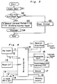
- step n1 the key of the learning remote control device which has been manipulated is read and, at subsequent step n2, a decision is made to determine if the key is a learnable key. If the result of decision at step n2 indicates the learnable key, a mode check takes place at step n3 and, in the event that the result of the mode check indicates the storing mode, the program flow proceeds to step n4 at which the random access memory is initialized, followed by step n5 at which a receiving process takes place.
- step n6 a decision is made to determine if an error has occurred during the receiving process and, in the event that the result of decision at stem n6 indicates that no error has occurred, the program flow proceeds to step n7 at which the carrier frequency is calculated, followed by step n8.
- a decision is made to determine if the received remote-control signal is an RC-5 signal.
- a decision is made to determine if it can be classified according to the category data stored in the storage means and, if it is possible to classify, it means that the received remote-control signal is the RC-5 signal and, therefore, the program flow proceeds to step n9, but if it is not possible to classify, it means that the received remote-control signal is not the RC-5 signal, but the generally used remote-control signal, and, therefore, the program flow proceeds to step n10 at which the categorization takes place in a manner similar to that effected with the generally used remote-control signal according to the prior art system.
- the remote-control signal is converted to provide the corresponding category number data, followed by step n11 at which, based on the decision by majority, the carrier frequency group is unified. Then at step n12, a decision is made to determine if an overflow takes place in the memory. If no overflow takes place in the memory, the program flow proceeds to step n13 at which a first processing terminates and an indicating sound requesting that the key should be manipulated again is outputted along with the lighting of a light emitting diode, followed by step n14.
- step n14 a decision is made to determine if the first received remote-control signal is an RC-5 signal and, in the event that the result of decision at step n14 indicates the RC-5 signal, the program flow proceeds to step n15 at which the category number data is recognized and, based on this recognized category number data, the reversed category number data are formulated, followed by step n16. However, if the result of decision at step n14 indicates that the first received remote-control signal is not the RC-5 signal, the program flow proceeds directly to step n16.
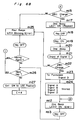
- step n16 the key of the learning remote control device which has been manipulated subsequently is read and, at subsequent step n17, a decision is made to determine if the first manipulated key is identical with the second manipulated key. If they are the same, the program flow proceeds to step n 18 at which a decision is made to determine if it is a learnable key. Should the result of decision at step n18 indicates that the key is the learnable key, step n19 takes place at which a mode check is carried out. In the event that the result of the mode check at step n19 indicates the storing mode, the program flow proceeds to step n20 at which the random access memory is initialized, followed by step n21 at which a receiving process takes place. Then, at step n22, a decision is made to determine if an error has occurred during the receiving process and, in the event that no error has occurred, the program flow proceeds to step n23 at which the carrier frequency is calculated, followed by step n24.
- step n24 and in the event that the received remote-control signal is the RC-5 signal, it is converted into the category number data as is the case with the first conversion, but in the event that it is not the RC-5 signal, the categorization takes place in a manner similar to that according to the prior art system, followed by step n25.
- step n25 a decision is made to determine if, in the case of the first received signal, that is, in the case of the RC-5 signal, the reversed category number data and the category number data of the second received signal are compared and, if the both coincide with each other, step n26 takes place at which the previous data of the same key number in a memory area is erased.
- step n27 actual one data is detected from the remote-control signal received repeatedly and continuously from a counter party and, using such data as the repeat start, the repeat length and the repeat number, the data are compressed, followed by step n28 at which they are stored in the memory. Then, at step n29, a decision is made to determine if an overflow occurs in the memory and, in the event that no overflow occur, the program flow proceeds to step n30 at which an electronic beep is generated along with the lighting of a light emitting diode to indicate that the storing operation has been completed.
- the RC-5 remote-control signal it is converted into the category number data and, based on this category number data, the reversed category number data in which the control bit has been reversed are formulated. Then, if this reversed category number data coincide with the category number data of the second received remote-control signal, such category number data are stored in the static random access memory. Accordingly, even the RC-5 remote-control signal can be learned.
- the received remote-control signal can be categorized into the plurality of the category data to provide the respective category number data for the required number of bits and, on the basis of the category number data, the reversed category number data corresponding to the remote-control signal wherein the particular bit of the remote-control signal is reversed are formulated.
- the reversed category number data corresponding to the first manipulation of the key during the storage mode and the category number data corresponding to the second manipulation of the key are then compared and, in the event that the both coincide with each other, the category number data can be stored in the memory. Therefore, each time the key of the remote control device is manipulated, the remote-control signal in which the code of particular bit varies can be stored
Landscapes
- Physics & Mathematics (AREA)
- General Physics & Mathematics (AREA)
- Engineering & Computer Science (AREA)
- Theoretical Computer Science (AREA)
- General Engineering & Computer Science (AREA)
- Selective Calling Equipment (AREA)
Claims (5)
- Procédé de mémorisation de commandes dans un dispositif de commande à distance à apprentissage comprenant les étapes de :i) réception (n5) d'un premier signal de commande à distance lors de la frappe d'une touche d'un dispositif de commande à distance devant être appris ;ii) classement par catégorie (n9) du premier signal de commande à distance en une première séquence d'éléments de données de catégorie, chaque élément de données de catégorie correspondant à une partie respective du premier signal de commande à distance ;iii) réception (n21) d'un second signal de commande à distance lors de la frappe suivante de ladite touche dudit dispositif de commande à distance devant être appris ;iv) classement par catégorie (n24) du second signal de commande à distance en une seconde séquence d'éléments de données de catégorie ;caractérisé par les étapes de :v) production (n15) d'une séquence de données de catégorie inversées correspondant audit premier signal de commande à distance dans lequel un bit de données particulier a été inversé ;vi) détermination (n25) de la correspondance éventuelle entre ladite seconde séquence d'éléments de données de catégorie et lesdites données de catégorie inversées ; etvii) mémorisation (n28) d'une desdites séquences d'éléments de données de catégorie en mémoire s'il est déterminé qu'une telle correspondance existe.
- Procédé selon la revendication 1, comprenant en outre l'étape de détermination (n8) du type particulier éventuel dudit premier signal de commande à distance, dans lequel un bit de données particulier s'inverse à chaque fois qu'une touche est enfoncée, dans lequel, si ledit premier signal de commande à distance n'est pas d'un tel type, l'étape v) est omise et lesdites première et seconde séquences de données de catégorie sont comparées à l'étape vi) pour déterminer si lesdites première et seconde séquences correspondent.
- Procédé selon la revendication 1 ou la revendication 2, dans lequel la séquence de données de catégorie mémorisée à l'étape vii) est comprimée (n27) avant mémorisation.
- Procédé selon l'une quelconque des revendications précédentes, dans lequel les éléments de données de catégorie utilisés pour former chaque séquence de données de catégorie pour ledit signal d'un type particulier ont été auparavant mémorisés en mémoire.
- Dispositif de commande à distance à apprentissage pour recevoir un signal de commande à distance, pour classer par catégorie le signal de commande à distance dans une séquence d'éléments de données de catégorie, pour les mémoriser dans une mémoire (14) et pour reproduire et émettre le signal de commande à distance sur la base de la séquence d'éléments de données de catégorie lus depuis la mémoire, ledit dispositif de commande à distance à apprentissage comprenant :un moyen de mémorisation (15) contenant des données de catégorie utilisées pour le classement par catégorie (n9, n10, n24) dudit signal de commande à distance ; etun moyen de conversion (15) pour classer par catégorie le signal de commande à distance reçu en fonction desdites données de catégorie dans une séquence d'éléments de données de catégorie (figure 10) ;caractérisé en ce que ledit dispositif de commande à distance à apprentissage est capable de recevoir un desdits signaux de commande à distance (figure 12) d'un type dans lequel un bit d'un signal de commande à distance s'inverse à chaque fois qu'une touche est enfoncée, et en ce qu'il comprend en outre :un moyen de formulation de séquence de données de catégorie inversées (15) pour formuler (n15) une séquence de données de catégorie inversées correspondant au signal de commande à distance dans lequel un bit de données particulier a été inversé ; etun moyen de comparaison (15) pour comparer (n25) une séquence de données de catégorie inversées, correspondant au signal de commande à distance reçu lors d'une première frappe d'une touche d'un dispositif de commande à distance devant être appris et une séquence de données de catégorie correspondant au signal de commande à distance reçu lors d'une seconde frappe de ladite touche ;dans lequel, lorsque la séquence de données de catégorie inversées correspondant à la première frappe de la touche et la séquence de données de catégorie correspondant à la seconde frappe de la touche coïncident l'une avec l'autre, une des séquences de données de catégorie est mémorisée (n28) en mémoire en réponse à une sortie du moyen de comparaison.
Applications Claiming Priority (6)
| Application Number | Priority Date | Filing Date | Title |
|---|---|---|---|
| JP18499/89 | 1989-01-27 | ||
| JP1018499A JPH0777468B2 (ja) | 1989-01-27 | 1989-01-27 | メモリーリモコン |
| JP1989019346U JPH0741272Y2 (ja) | 1989-02-20 | 1989-02-20 | 学習リモコン |
| JP19346/89 | 1989-02-20 | ||
| JP5386089U JPH0649031Y2 (ja) | 1989-05-09 | 1989-05-09 | 学習リモコン |
| JP53860/89 | 1989-05-09 |
Publications (3)
| Publication Number | Publication Date |
|---|---|
| EP0380371A2 EP0380371A2 (fr) | 1990-08-01 |
| EP0380371A3 EP0380371A3 (fr) | 1992-04-08 |
| EP0380371B1 true EP0380371B1 (fr) | 1996-08-14 |
Family
ID=27282226
Family Applications (1)
| Application Number | Title | Priority Date | Filing Date |
|---|---|---|---|
| EP90300862A Expired - Lifetime EP0380371B1 (fr) | 1989-01-27 | 1990-01-26 | Dispositif de commande à distance avec mémoire |
Country Status (6)
| Country | Link |
|---|---|
| US (1) | US5043723A (fr) |
| EP (1) | EP0380371B1 (fr) |
| KR (1) | KR920010961B1 (fr) |
| DE (1) | DE69028026T2 (fr) |
| ES (1) | ES2092489T3 (fr) |
| MY (1) | MY104831A (fr) |
Families Citing this family (17)
| Publication number | Priority date | Publication date | Assignee | Title |
|---|---|---|---|---|
| NL9000603A (nl) * | 1990-03-16 | 1991-10-16 | Philips Nv | Afstandsbedieningssysteem, alsmede een zender en een ontvanger voor een afstandsbedieningssysteem. |
| KR930006419B1 (ko) * | 1990-10-26 | 1993-07-14 | 삼성전자 주식회사 | 재편성원격제어송신기의 모드전환 및 표시방법 |
| KR930006424B1 (ko) * | 1990-10-27 | 1993-07-14 | 삼성전자 주식회사 | 재편성원격제어송신기의 펄스잡음검출 및 정정방법 |
| US5691710A (en) * | 1992-11-02 | 1997-11-25 | Zenith Electronics Corporation | Self learning IR remote control transmitter |
| DE4308441A1 (de) * | 1993-03-17 | 1994-09-22 | Thomson Brandt Gmbh | Verfahren und Vorrichtung zur Fernbedienung |
| JPH077771A (ja) * | 1993-03-19 | 1995-01-10 | Sony Corp | リモートコマンダー |
| EP1317153B1 (fr) * | 1993-06-15 | 2011-07-27 | Celltrace LLC | Système de télécommunications |
| GB2305276A (en) * | 1995-09-15 | 1997-04-02 | Thomson Multimedia Sa | Learning remote control IR codes |
| JP2943712B2 (ja) * | 1996-08-23 | 1999-08-30 | 日本電気株式会社 | 遠隔制御方式 |
| US5850304A (en) * | 1997-01-08 | 1998-12-15 | Scottsdale Technologies, Inc. | Optically programmable controller |
| JP4034269B2 (ja) * | 2002-02-19 | 2008-01-16 | シャープ株式会社 | ディスプレイ装置、電子機器 |
| US20040125074A1 (en) * | 2002-12-31 | 2004-07-01 | Chin-Shu Lin | Multi-function remote controller |
| US7613893B2 (en) * | 2004-06-22 | 2009-11-03 | Intel Corporation | Remote audio |
| DE102005024204A1 (de) * | 2005-05-25 | 2006-11-30 | Vishay Semiconductor Gmbh | Infrarotfernsteuersignal-Verarbeitungsschaltung |
| US8545323B2 (en) * | 2006-06-30 | 2013-10-01 | Logitech Europe S.A. | Video game controller with compact and efficient force feedback mechanism |
| US7797598B1 (en) * | 2006-11-14 | 2010-09-14 | Xilinx, Inc. | Dynamic timer for testbench interface synchronization |
| CN103186978B (zh) * | 2011-12-30 | 2015-09-30 | 无锡华润矽科微电子有限公司 | 控制红外遥控发射的电路结构 |
Family Cites Families (6)
| Publication number | Priority date | Publication date | Assignee | Title |
|---|---|---|---|---|
| FR2528201B1 (fr) * | 1982-06-04 | 1985-12-27 | Jacques Lewiner | Perfectionnements aux dispositifs de telecommande a code |
| US4535333A (en) * | 1982-09-23 | 1985-08-13 | Chamberlain Manufacturing Corporation | Transmitter and receiver for controlling remote elements |
| US4626848A (en) * | 1984-05-15 | 1986-12-02 | General Electric Company | Programmable functions for reconfigurable remote control |
| US4623887A (en) * | 1984-05-15 | 1986-11-18 | General Electric Company | Reconfigurable remote control |
| JPH0728448B2 (ja) * | 1986-02-07 | 1995-03-29 | アールシーエー トムソン ライセンシング コーポレイシヨン | 再構成可能な遠隔制御送信器 |
| US4866434A (en) * | 1988-12-22 | 1989-09-12 | Thomson Consumer Electronics, Inc. | Multi-brand universal remote control |
-
1990
- 1990-01-25 MY MYPI90000128A patent/MY104831A/en unknown
- 1990-01-26 ES ES90300862T patent/ES2092489T3/es not_active Expired - Lifetime
- 1990-01-26 DE DE69028026T patent/DE69028026T2/de not_active Expired - Lifetime
- 1990-01-26 EP EP90300862A patent/EP0380371B1/fr not_active Expired - Lifetime
- 1990-01-26 US US07/470,935 patent/US5043723A/en not_active Expired - Lifetime
- 1990-01-29 KR KR1019900000955A patent/KR920010961B1/ko not_active Expired
Also Published As
| Publication number | Publication date |
|---|---|
| DE69028026T2 (de) | 1997-02-20 |
| DE69028026D1 (de) | 1996-09-19 |
| US5043723A (en) | 1991-08-27 |
| EP0380371A2 (fr) | 1990-08-01 |
| ES2092489T3 (es) | 1996-12-01 |
| EP0380371A3 (fr) | 1992-04-08 |
| KR920010961B1 (ko) | 1992-12-26 |
| MY104831A (en) | 1994-06-30 |
| KR900012162A (ko) | 1990-08-03 |
Similar Documents
| Publication | Publication Date | Title |
|---|---|---|
| US5043723A (en) | Memory remote control device | |
| KR920002229B1 (ko) | 재구성 가능한 원격 제어 송신기 | |
| US6097309A (en) | Remote control learning system and method using signal envelope pattern recognition | |
| EP0935226B1 (fr) | Procédé et dispositif de mémorisation d'un signal numérique codé | |
| US4628541A (en) | Infra-red data communications system for coupling a battery powered data entry device to a microcomputer | |
| US4425647A (en) | IR Remote control system | |
| EP0162327B1 (fr) | Méthode numérique de commande à distance | |
| KR870008482A (ko) | 프로그램 작성 가능한 원격 제어 송신기 | |
| US5670958A (en) | Remote control method and device | |
| JPS60254898A (ja) | 再構成可能なリモコン送信器 | |
| JPS594906B2 (ja) | デジタルデ−タを伝送する方法および装置 | |
| US5155741A (en) | High data rate long pulse compression waveform communication system for M-ary encoding voice messages for air traffic control systems | |
| JPS63296425A (ja) | 通信方法及び符号化装置 | |
| US3987414A (en) | Digital remote control for electronic signal receivers | |
| US5588023A (en) | High content information transmission system | |
| US4809299A (en) | Frequency independent information transmission system | |
| US4020449A (en) | Signal transmitting and receiving device | |
| US4445175A (en) | Supervisory remote control system employing pseudorandom sequence | |
| US4186345A (en) | Remote control system | |
| JPS6246099B2 (fr) | ||
| JPH0649031Y2 (ja) | 学習リモコン | |
| US5363439A (en) | DTMF signal receiving system | |
| SU1325718A1 (ru) | Устройство дл передачи двоичного кода | |
| KR940027486A (ko) | 만능원격제어 송신기 및 그의 제어방법 | |
| KR0176830B1 (ko) | 다수의 리모콘 신호 수신방법 |
Legal Events
| Date | Code | Title | Description |
|---|---|---|---|
| PUAI | Public reference made under article 153(3) epc to a published international application that has entered the european phase |
Free format text: ORIGINAL CODE: 0009012 |
|
| AK | Designated contracting states |
Kind code of ref document: A2 Designated state(s): DE ES FR GB |
|
| 17P | Request for examination filed |
Effective date: 19901214 |
|
| PUAL | Search report despatched |
Free format text: ORIGINAL CODE: 0009013 |
|
| AK | Designated contracting states |
Kind code of ref document: A3 Designated state(s): DE ES FR GB |
|
| 17Q | First examination report despatched |
Effective date: 19940622 |
|
| GRAH | Despatch of communication of intention to grant a patent |
Free format text: ORIGINAL CODE: EPIDOS IGRA |
|
| GRAH | Despatch of communication of intention to grant a patent |
Free format text: ORIGINAL CODE: EPIDOS IGRA |
|
| GRAA | (expected) grant |
Free format text: ORIGINAL CODE: 0009210 |
|
| AK | Designated contracting states |
Kind code of ref document: B1 Designated state(s): DE ES FR GB |
|
| REF | Corresponds to: |
Ref document number: 69028026 Country of ref document: DE Date of ref document: 19960919 |
|
| ET | Fr: translation filed | ||
| REG | Reference to a national code |
Ref country code: ES Ref legal event code: FG2A Ref document number: 2092489 Country of ref document: ES Kind code of ref document: T3 |
|
| PLBE | No opposition filed within time limit |
Free format text: ORIGINAL CODE: 0009261 |
|
| STAA | Information on the status of an ep patent application or granted ep patent |
Free format text: STATUS: NO OPPOSITION FILED WITHIN TIME LIMIT |
|
| 26N | No opposition filed | ||
| REG | Reference to a national code |
Ref country code: GB Ref legal event code: IF02 |
|
| PGFP | Annual fee paid to national office [announced via postgrant information from national office to epo] |
Ref country code: ES Payment date: 20090203 Year of fee payment: 20 |
|
| PGFP | Annual fee paid to national office [announced via postgrant information from national office to epo] |
Ref country code: DE Payment date: 20090123 Year of fee payment: 20 |
|
| PGFP | Annual fee paid to national office [announced via postgrant information from national office to epo] |
Ref country code: GB Payment date: 20090121 Year of fee payment: 20 |
|
| PGFP | Annual fee paid to national office [announced via postgrant information from national office to epo] |
Ref country code: FR Payment date: 20090113 Year of fee payment: 20 |
|
| REG | Reference to a national code |
Ref country code: GB Ref legal event code: PE20 Expiry date: 20100125 |
|
| REG | Reference to a national code |
Ref country code: ES Ref legal event code: FD2A Effective date: 20100127 |
|
| PG25 | Lapsed in a contracting state [announced via postgrant information from national office to epo] |
Ref country code: ES Free format text: LAPSE BECAUSE OF EXPIRATION OF PROTECTION Effective date: 20100127 |
|
| PG25 | Lapsed in a contracting state [announced via postgrant information from national office to epo] |
Ref country code: GB Free format text: LAPSE BECAUSE OF EXPIRATION OF PROTECTION Effective date: 20100125 |
|
| PG25 | Lapsed in a contracting state [announced via postgrant information from national office to epo] |
Ref country code: DE Free format text: LAPSE BECAUSE OF EXPIRATION OF PROTECTION Effective date: 20100126 |