EP0381136A1 - Voie porteuse pour véhicules magnétiques - Google Patents
Voie porteuse pour véhicules magnétiques Download PDFInfo
- Publication number
- EP0381136A1 EP0381136A1 EP90101794A EP90101794A EP0381136A1 EP 0381136 A1 EP0381136 A1 EP 0381136A1 EP 90101794 A EP90101794 A EP 90101794A EP 90101794 A EP90101794 A EP 90101794A EP 0381136 A1 EP0381136 A1 EP 0381136A1
- Authority
- EP
- European Patent Office
- Prior art keywords
- guideway
- concrete
- girder
- steel
- track
- Prior art date
- Legal status (The legal status is an assumption and is not a legal conclusion. Google has not performed a legal analysis and makes no representation as to the accuracy of the status listed.)
- Granted
Links
- 230000005291 magnetic effect Effects 0.000 title claims abstract description 9
- 229910000831 Steel Inorganic materials 0.000 claims abstract description 44
- 239000010959 steel Substances 0.000 claims abstract description 44
- 239000002131 composite material Substances 0.000 claims abstract description 20
- 239000011513 prestressed concrete Substances 0.000 claims abstract description 11
- 239000011150 reinforced concrete Substances 0.000 claims abstract description 4
- 239000004567 concrete Substances 0.000 claims description 25
- 238000010276 construction Methods 0.000 claims description 17
- 238000004519 manufacturing process Methods 0.000 claims description 14
- 238000003466 welding Methods 0.000 claims description 4
- 210000002435 tendon Anatomy 0.000 claims description 3
- 238000000151 deposition Methods 0.000 claims description 2
- 239000011440 grout Substances 0.000 claims 1
- 230000002787 reinforcement Effects 0.000 claims 1
- 238000009826 distribution Methods 0.000 abstract description 5
- 238000012546 transfer Methods 0.000 abstract description 2
- 239000000969 carrier Substances 0.000 abstract 6
- 230000008878 coupling Effects 0.000 abstract 1
- 238000010168 coupling process Methods 0.000 abstract 1
- 238000005859 coupling reaction Methods 0.000 abstract 1
- 238000013461 design Methods 0.000 description 5
- 238000009415 formwork Methods 0.000 description 4
- 125000006850 spacer group Chemical group 0.000 description 4
- 238000005096 rolling process Methods 0.000 description 3
- 229910000746 Structural steel Inorganic materials 0.000 description 2
- 238000005260 corrosion Methods 0.000 description 2
- 230000007797 corrosion Effects 0.000 description 2
- 238000000034 method Methods 0.000 description 2
- 230000003014 reinforcing effect Effects 0.000 description 2
- 238000004904 shortening Methods 0.000 description 2
- 238000003860 storage Methods 0.000 description 2
- 238000012549 training Methods 0.000 description 2
- 150000001875 compounds Chemical class 0.000 description 1
- 230000002844 continuous effect Effects 0.000 description 1
- 238000012937 correction Methods 0.000 description 1
- 238000011161 development Methods 0.000 description 1
- 230000018109 developmental process Effects 0.000 description 1
- 238000010586 diagram Methods 0.000 description 1
- 230000008030 elimination Effects 0.000 description 1
- 238000003379 elimination reaction Methods 0.000 description 1
- 230000002349 favourable effect Effects 0.000 description 1
- 238000009434 installation Methods 0.000 description 1
- 230000007774 longterm Effects 0.000 description 1
- 239000002184 metal Substances 0.000 description 1
- 239000011178 precast concrete Substances 0.000 description 1
- 230000005855 radiation Effects 0.000 description 1
- 230000036561 sun exposure Effects 0.000 description 1
- 230000036962 time dependent Effects 0.000 description 1
- 238000004804 winding Methods 0.000 description 1
Images



Classifications
-
- E—FIXED CONSTRUCTIONS
- E01—CONSTRUCTION OF ROADS, RAILWAYS, OR BRIDGES
- E01B—PERMANENT WAY; PERMANENT-WAY TOOLS; MACHINES FOR MAKING RAILWAYS OF ALL KINDS
- E01B25/00—Tracks for special kinds of railways
- E01B25/30—Tracks for magnetic suspension or levitation vehicles
- E01B25/305—Rails or supporting constructions
Definitions
- the invention relates to guideway supports for magnetic tracks and the like.
- Track-bound transport systems to which the stators of linear motors can be attached and which absorb all loads, in particular as a result of carrying, guiding, driving, braking and depositing the vehicles.
- Magnetic tracks of the above type reach very high speeds of up to 500 km / h or more.
- the magnetic railway vehicles travel on guideway girders, which in turn rest on supports and / or foundations erected on the building ground (ground).
- the guideway girders must ensure that all loads occurring during driving operation can be absorbed and reliably transferred to the substructures (supports and foundations) and the foundation.
- the guideway supports must follow the specified route in terms of route and gradient (this is the target line of the road) very precisely. This applies in particular to the positional accuracy of the functional surfaces and -components that are required on the guideway girders for driving.
- the guideway supports essentially require the following functional surfaces and components for magnetic railway operation: - lateral guide rails, the distance between which forms the track width, - Sliding levels for parking the vehicles and - Construction parts to which the stators of linear motors, with the help of which the magnetic effect is generated, are attached.
- the previously known guideway girders consist of steel girders or prestressed concrete girders.
- the three above-mentioned functional components are three individual parts which have to be connected to one another and to the steel guideway supports by means of screws or corresponding, preferably adjustable fastening means in an extremely precise position.
- the three above-mentioned functional components are an integral part of the welded steel guideway girders.
- the known guideway girders in concrete construction consist of prestressed concrete girders into which steel anchor bodies are concreted as construction parts for the positionally correct connection (fastening) of the stators. After the prestressed concrete beams have been manufactured, the steel side guide rails are attached in a subsequent separate operation.
- the steel girder design with the screwed-on functional components requires very high expenditures for production and corrosion protection.
- the fully welded steel girder version is cheaper in terms of corrosion protection, but even here the required high positional accuracy of the functional components can only be achieved with cost-intensive measures during production, as is also the case with the prestressed concrete girders.
- the thickness tolerances of the steel side guide rails that occur during their manufacture in the rolling mill are a major reason for the measures required in the manufacture of the guideway girders. These thickness tolerances are already of the same order of magnitude as is permitted for the finished guideway construction.
- the invention has for its object to provide a guideway girder which has favorable properties for the load-bearing and the deformation behavior, which is maintenance-free as long as possible, and whose target shape can be achieved with high accuracy in a cost-effective manufacturing process.
- the guideway girder consists of steel structures, which are connected in a shear-resistant manner to a composite girder with reinforced concrete or prestressed concrete by means of a composite, and that the side guide rails of the guideway girder are welded to the steel structures.
- the shear-resistant connection of the steel structures with reinforced concrete or prestressed concrete creates a composite girder that has a higher rigidity than steel girders, which reduces the deformation due to traffic loads.
- the deformation due to different temperature distribution in the guideway girder e.g. due to solar radiation
- the welding of the side guide rails to the steel structures of the girder represents a secure connection with a long service life.
- the steel structures of the guideway girder can be prefabricated individually and used as formwork or formwork aids for concreting.
- the rolling tolerances of the steel side guide rails can thereby be eliminated and the target shape of the guideway girder can be reliably achieved with little effort if adjustable devices with side stops are used.
- composite girders are lighter in weight than prestressed concrete girders. This results in advantages for production, for equipping the guideway girders with stators (linear motor) and for the assembly process on the construction site, since the capacities of the means of transport and the lifting devices can be designed accordingly smaller.
- steel needles according to claim 2 instead of reinforcing bars or structural steel mesh mats enables a simple and safe method for increasing the tensile strength of the concrete, particularly in the area of difficult to access areas. Places that are difficult to access are e.g. for the side guide rails and sliding levels (on the top flange) and in the area of the bottom flange.
- the desired shape of the guideway girder can be achieved by subsequent tightening if it has not been achieved sufficiently enough during the manufacturing process.
- prefabricated concrete parts according to claim 4 has the advantage that they can be produced completely separately from the rest of the support structure and that after a temporary storage the shortening due to the shrinkage of the concrete has already taken place and has ended. Without storage time, the shortening must be taken into account as the planned deformation of the guideway girder.
- the maximum transport and lifting weights can also be reduced with precast concrete elements, which is important when considering the long distances to be built.
- continuous girders By connecting two or more guideway girders, the length and weight of which are limited, so-called continuous girders can be created at the construction site, which are supported in the longitudinal direction by more than two support points (supports, foundations). With continuous beams, the deformations due to traffic loads and due to different temperature distribution are significantly less than with single span beams (with only 2 supports). It has been shown that the connection of the concrete parts to achieve the continuous effect is not necessary and the connection of the steel parts of the adjoining guideway girders by welding or screwing is sufficient. Continuous girders with a large length are thus realized, but the weight and the length of the to the construction site transporting single girders remain below the economically justifiable limits for transport and assembly on the construction site.
- a composite guideway beam is shown in cross section.
- the concrete slab 1 on the upper flange 10 and the concrete body 1 on the lower flange 11 are connected to the steel structure 3 in a shear-resistant manner with the aid of composite means 4.
- the steel structure 3 arranged below the upper chord 10 consists of two lateral longitudinal plates which are welded to transverse bulkheads 7, so that they form a type of trough together with the lower chord. This creates a very stable composite support structure.
- the side guide rails 5 are firmly welded to the two steel structures 3 of the upper chord 10. This ensures exact compliance with the gauge in a particularly permanent connection.
- the tendons 2 can be used to increase the load capacity, to reduce the deflection due to creeping of the concrete and subsequent correction of the carrier shape can be used.
- Steel sheets serve as sliding planes 6, the spacers 8 of which serve at the same time as a compound.
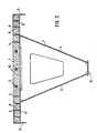
- FIG. 2 shows a composite girder construction for the guideway which differs from the construction shown in FIG. 1 in the area of the functional components (side guide rail 5, sliding plane 6) and the lower flange 11.
- a sheet metal is welded to the upper end of the side guide rails 5 perpendicular to them, which serves for load transfer and at the same time contains the two sliding planes 6.
- This constructive training is cheaper in terms of durability than the solution shown in Fig. 1.
- the lower flange 11 is made of sheet steel and has no concrete body. The support should be built with a corresponding length increase during production. By the time of commissioning, this increase is largely reduced by the shrinkage of the concrete 1 in the upper chord 10.
- a lower flange 11 without concrete can also be used in the embodiment according to FIG. 1.
- Fig. 3 illustrates the advantages that are achieved in the manufacture of the composite support structure according to the invention.
- the manufacture takes place in a position rotated by 180 ° and in devices 9 which - which is not shown in the drawing - can be adjusted or selected with regard to their dimensions such that the desired shape of the composite construction can be specified with them.
- the side guide rails 5 are part of two separate steel structures 3, these can be on the side Stops of the devices 9 are fixed. This eliminates the unavoidable thickness tolerances of the side guide rails 5 from the rolling process, so that compliance with the track width defined by the distance between the two side guide rails 5 is ensured.
- the adjustable devices 9 and the two steel structures 3 serve as formwork.
- the further, trough-like steel construction 3 with transverse bulkheads 7 made of steel is manufactured in separate devices.
- This trough-like steel structure 3 can be welded to the two steel structures 3 connected to the concrete slab 1 with the side guide rails 5 without difficulty, since only the usual manufacturing and assembly tolerances of the steel structure have to be observed.
- the two side guide rails 5 are welded to a continuous cover plate 14, to which the composite means 4 are also fastened, preferably welded.
- the elimination of the thickness tolerances of the side guide rails 5, as can be seen immediately in FIG. 4, is ensured by the position of the weld seams 15 and their design.
- the concrete body 1 can then be concreted using the customary construction methods, the steel structure 3 serving in part as formwork. 4, the functional components or surfaces (side guide rails 5 and sliding planes 6) are an integral part of a continuous (one-piece) steel structure 3. This also offers considerable advantages for the durability of the guideway girders, in view of the fact that the girders when later driving operations are exposed to all weather influences for decades.
Landscapes
- Engineering & Computer Science (AREA)
- Mechanical Engineering (AREA)
- Architecture (AREA)
- Civil Engineering (AREA)
- Structural Engineering (AREA)
- Railway Tracks (AREA)
Applications Claiming Priority (2)
| Application Number | Priority Date | Filing Date | Title |
|---|---|---|---|
| DE3902949A DE3902949A1 (de) | 1989-02-01 | 1989-02-01 | Fahrwegtraeger fuer magnetbahnen |
| DE3902949 | 1989-02-01 |
Publications (2)
| Publication Number | Publication Date |
|---|---|
| EP0381136A1 true EP0381136A1 (fr) | 1990-08-08 |
| EP0381136B1 EP0381136B1 (fr) | 1992-09-16 |
Family
ID=6373219
Family Applications (1)
| Application Number | Title | Priority Date | Filing Date |
|---|---|---|---|
| EP90101794A Expired - Lifetime EP0381136B1 (fr) | 1989-02-01 | 1990-01-30 | Voie porteuse pour véhicules magnétiques |
Country Status (9)
| Country | Link |
|---|---|
| US (1) | US5027713A (fr) |
| EP (1) | EP0381136B1 (fr) |
| JP (1) | JPH02248501A (fr) |
| CN (1) | CN1044836A (fr) |
| AU (1) | AU631839B2 (fr) |
| CA (1) | CA2009132C (fr) |
| DD (1) | DD291792A5 (fr) |
| DE (2) | DE3902949A1 (fr) |
| RU (1) | RU2023785C1 (fr) |
Cited By (6)
| Publication number | Priority date | Publication date | Assignee | Title |
|---|---|---|---|---|
| EP0498711B1 (fr) * | 1991-02-05 | 1994-02-23 | Cogifer Compagnie Generale D'installations Ferroviaires | Appareil de voie pour véhicules ferroviaires sur pneumatiques à galet de guidage médian et procédé pour sa fabrication |
| WO2004063466A1 (fr) * | 2003-01-14 | 2004-07-29 | Schmitt Stumpf Frühauf und Partner Ingenieurgesellschaft im Bauwesen mbH | Piste pour trains a sustentation magnetique, et son procede de production |
| WO2004085744A1 (fr) * | 2003-03-25 | 2004-10-07 | Thyssenkrupp Transrapid Gmbh | Tablier et voie de sustentation magnetique realisee avec un tel tablier |
| WO2005121454A1 (fr) * | 2004-06-14 | 2005-12-22 | Thyssenkrupp Transrapid Gmbh | Tablier et voie de sustentation magnetique comportant ce tablier |
| US8826824B2 (en) | 2006-03-03 | 2014-09-09 | Hm Attractions Inc. | Linear motor driven system and method |
| US9358472B2 (en) | 2011-06-30 | 2016-06-07 | Hm Attractions, Inc. | Motion control system and method for an amusement ride |
Families Citing this family (38)
| Publication number | Priority date | Publication date | Assignee | Title |
|---|---|---|---|---|
| DE4115935C2 (de) * | 1991-05-16 | 1996-11-07 | Dyckerhoff & Widmann Ag | Fahrwegkonstruktion für Magnetschwebefahrzeuge |
| DE4219200C2 (de) * | 1992-06-12 | 1997-01-23 | Thyssen Industrie | Fahrweg für Magnetbahnen |
| CA2142292A1 (fr) * | 1992-08-14 | 1994-03-03 | Phillip A. Fischer | Monorail a moteur a induction |
| US5653173A (en) * | 1992-08-14 | 1997-08-05 | Fischer; Phillip A. | Induction motor monorail system |
| DE4306166C2 (de) * | 1993-02-27 | 1997-09-11 | Magnetbahn Gmbh | Trogförmiger Fahrwegträger für Magnetschwebefahrzeuge und Verfahren zur Herstellung des Fahrwegträgers |
| US5511488A (en) * | 1994-04-25 | 1996-04-30 | Powell; James R. | Electromagnetic induction ground vehicle levitation guideway |
| DE19808622C2 (de) * | 1998-02-28 | 2001-12-13 | Max Boegl Bauunternehmung | Fahrweg |
| US5953996A (en) * | 1998-04-03 | 1999-09-21 | Powell; James R. | System and method for magnetic levitation guideway emplacement on conventional railroad line installations |
| DE19829900B4 (de) * | 1998-07-06 | 2011-05-05 | Berding Beton Gmbh | Fahrbahn einer Magnetbahn |
| DE19946105A1 (de) * | 1999-09-16 | 2001-03-22 | Thyssen Transrapid System Gmbh | Träger zur Herstellung eines Fahrwegs für spurgebundene Fahrzeuge, insbesondere einer Magnetschwebebahn, und damit hergestellter Fahrweg |
| DE19945749C1 (de) * | 1999-09-24 | 2001-12-06 | Brueckenbau Plauen Gmbh | Fahrwegträger |
| US6951433B2 (en) | 2000-08-04 | 2005-10-04 | Dieter Reichel | Device for nonpositively fixing a bracket to a supporting base body |
| DE10038851A1 (de) | 2000-08-04 | 2002-02-14 | Boegl Max Bauunternehmung Gmbh | Verfahren zum Herstellen einer Verbindungsstelle an einem Fahrweg |
| JP2004509247A (ja) * | 2000-09-12 | 2004-03-25 | マクス、ベグル、バウウンテルネームング、ゲゼルシャフト、ミット、ベシュレンクテル、ハフツング、ウント、コンパニー、コマンディトゲゼルシャフト | 走行路支持体 |
| US6554199B1 (en) * | 2000-10-06 | 2003-04-29 | Pfleiderer Infrastrukturtechnick Gmbh & Co., Kg | Trackway for transrapid |
| AU777666B2 (en) * | 2000-10-16 | 2004-10-28 | Rail.One Gmbh | Travel way for land transport systems |
| KR20020031674A (ko) * | 2000-10-23 | 2002-05-03 | 추후제출 | 경량궤도차용 차도 |
| US6708623B2 (en) | 2001-08-16 | 2004-03-23 | Judith Marie Cummins | Support structure |
| CN1143027C (zh) * | 2001-09-07 | 2004-03-24 | 上海磁悬浮交通发展有限公司 | 高速轨道交通的轨道结构 |
| DE10148949A1 (de) * | 2001-10-04 | 2003-06-05 | Hochtief Ag Hoch Tiefbauten | Anbauelement für Fahrwegträger von Magnetschwebebahnen |
| AU2003273369A1 (en) * | 2002-05-28 | 2003-12-19 | Thyssenkrupp Technologies Ag | Driveway, driveway module, and method for the production thereof |
| DE10240808A1 (de) * | 2002-08-30 | 2004-03-11 | Walter Bau-Ag | Magnetbahnfahrweg aus Stahlträgern im Verbund mit Fahrwegelementen aus Betonfertigteilen |
| EP1579077A4 (fr) * | 2002-12-30 | 2008-10-22 | Koo Min Se | Poutre mixte precontrainte, structure de poutre mixte precontrainte en continu et procedes de fabrication et de raccordement correspondants |
| DE10332253A1 (de) * | 2003-03-20 | 2004-09-30 | Hirschfeld, Inc., San Angelo | Verfahren zur Errichtung eines Fahrweges für eine Magnetschwebebahn |
| US7347350B2 (en) * | 2003-08-26 | 2008-03-25 | Lincoln Global, Inc. | Welding workpiece support structures |
| US7357290B2 (en) * | 2003-08-26 | 2008-04-15 | Lincoln Global, Inc. | Workpiece support structures and system for controlling same |
| DE102008005888A1 (de) * | 2008-01-22 | 2009-07-23 | Thyssenkrupp Transrapid Gmbh | Magnetschwebebahn |
| US8161691B2 (en) | 2008-05-14 | 2012-04-24 | Plattforms, Inc. | Precast composite structural floor system |
| US8297017B2 (en) | 2008-05-14 | 2012-10-30 | Plattforms, Inc. | Precast composite structural floor system |
| US8453406B2 (en) | 2010-05-04 | 2013-06-04 | Plattforms, Inc. | Precast composite structural girder and floor system |
| US8381485B2 (en) | 2010-05-04 | 2013-02-26 | Plattforms, Inc. | Precast composite structural floor system |
| CN102140777B (zh) * | 2011-04-01 | 2013-01-16 | 深圳市市政设计研究院有限公司 | 一种多弦杆组合梁结构 |
| USD684221S1 (en) * | 2012-07-10 | 2013-06-11 | Innovation First, Inc. | Toy track support component |
| CN103512739B (zh) * | 2013-09-25 | 2015-09-02 | 合肥工业大学 | 对金属构件施加有效预应力的自平衡体系 |
| KR102605011B1 (ko) * | 2015-01-09 | 2023-11-24 | 다이내믹 어트랙션스 리미티드 | V-트랙 지지 구조 컴포넌트 |
| CN106245512B (zh) * | 2016-08-04 | 2018-05-04 | 浙江工业大学 | 钢-橡胶混凝土扣件式组合箱梁 |
| CN109683145B (zh) * | 2018-12-14 | 2021-05-07 | 中国航空工业集团公司北京航空精密机械研究所 | 大尺寸边缘驱动旋转转台的台体 |
| CN110965405A (zh) * | 2019-12-20 | 2020-04-07 | 重庆艾博瑞威轨道交通设备有限公司 | 一种新型单轨轨道梁 |
Citations (5)
| Publication number | Priority date | Publication date | Assignee | Title |
|---|---|---|---|---|
| FR1136874A (fr) * | 1954-10-05 | 1957-05-21 | Alweg Forschung Gmbh | Voie ou élément porteur pour véhicules du type monorail |
| DE2434125B1 (de) * | 1974-07-12 | 1975-09-04 | Mohammed Ismail Arbab | Tragschiene für eine Schnellbahn |
| DE2744367A1 (de) * | 1977-10-01 | 1979-04-05 | Maschf Augsburg Nuernberg Ag | Aufgestaenderter fahrweg fuer hochleistungsschnellbahnen |
| DE2914907A1 (de) * | 1979-04-12 | 1980-10-30 | Thyssen Industrie | Brueckenartiger fahrbahntraeger fuer magnet-schwebebahnen |
| EP0151283A2 (fr) * | 1984-02-06 | 1985-08-14 | Thyssen Industrie Ag | Procédé pour la fixation précise d'éléments d'équipement à l'appareil porteur de voies carrossables et appareil porteur formé de façon adéquate |
Family Cites Families (11)
| Publication number | Priority date | Publication date | Assignee | Title |
|---|---|---|---|---|
| US3771033A (en) * | 1970-07-07 | 1973-11-06 | Japan National Railway | Apparatus for propelling a movable body in a suspended state at a very high speed |
| US3892185A (en) * | 1970-12-11 | 1975-07-01 | Rockwell International Corp | Low drag magnetic suspension system |
| SE373821B (fr) * | 1972-02-29 | 1975-02-17 | Swedish Rail System Ab Srs | |
| DE2239656A1 (de) * | 1972-08-12 | 1974-02-28 | Maschf Augsburg Nuernberg Ag | Fahrbahnkoerper fuer hochleistungsschnellbahnen |
| US3920182A (en) * | 1973-11-23 | 1975-11-18 | George Molyneux | Heavy duty rail track assemblies |
| NL7416664A (nl) * | 1974-02-05 | 1975-08-07 | Krauss Maffei Ag | Lineaire inductiemotor. |
| JPS5253317A (en) * | 1975-10-28 | 1977-04-28 | Toshiba Corp | Guide for magnetic floating vehicle |
| FR2359245A1 (fr) * | 1976-07-23 | 1978-02-17 | Vivion Robert | Dispositif de fixation de voie ferree sur longrines disposees bout a bo |
| LU77749A1 (de) * | 1977-07-12 | 1979-03-26 | Arbed | Verbundtraeger |
| FR2494400A1 (fr) * | 1980-11-14 | 1982-05-21 | Campenon Bernard | Perfectionnement aux ouvrages mixtes beton-acier de genie civil a ames metalliques d'elements de beton |
| IT1176498B (it) * | 1984-07-27 | 1987-08-18 | I P A Ind Prefabbricati Affini | Componenti per linee ferroviarie su piastre prefabbricate in cemento armato,senza massicciata |
-
1989
- 1989-02-01 DE DE3902949A patent/DE3902949A1/de not_active Withdrawn
-
1990
- 1990-01-30 DE DE9090101794T patent/DE59000298D1/de not_active Expired - Fee Related
- 1990-01-30 EP EP90101794A patent/EP0381136B1/fr not_active Expired - Lifetime
- 1990-01-31 US US07/472,830 patent/US5027713A/en not_active Expired - Lifetime
- 1990-01-31 RU SU904743174A patent/RU2023785C1/ru not_active IP Right Cessation
- 1990-02-01 CN CN90101163A patent/CN1044836A/zh active Pending
- 1990-02-01 AU AU49047/90A patent/AU631839B2/en not_active Ceased
- 1990-02-01 CA CA002009132A patent/CA2009132C/fr not_active Expired - Fee Related
- 1990-02-01 JP JP2020530A patent/JPH02248501A/ja active Pending
- 1990-02-01 DD DD90337488A patent/DD291792A5/de not_active IP Right Cessation
Patent Citations (5)
| Publication number | Priority date | Publication date | Assignee | Title |
|---|---|---|---|---|
| FR1136874A (fr) * | 1954-10-05 | 1957-05-21 | Alweg Forschung Gmbh | Voie ou élément porteur pour véhicules du type monorail |
| DE2434125B1 (de) * | 1974-07-12 | 1975-09-04 | Mohammed Ismail Arbab | Tragschiene für eine Schnellbahn |
| DE2744367A1 (de) * | 1977-10-01 | 1979-04-05 | Maschf Augsburg Nuernberg Ag | Aufgestaenderter fahrweg fuer hochleistungsschnellbahnen |
| DE2914907A1 (de) * | 1979-04-12 | 1980-10-30 | Thyssen Industrie | Brueckenartiger fahrbahntraeger fuer magnet-schwebebahnen |
| EP0151283A2 (fr) * | 1984-02-06 | 1985-08-14 | Thyssen Industrie Ag | Procédé pour la fixation précise d'éléments d'équipement à l'appareil porteur de voies carrossables et appareil porteur formé de façon adéquate |
Cited By (9)
| Publication number | Priority date | Publication date | Assignee | Title |
|---|---|---|---|---|
| EP0498711B1 (fr) * | 1991-02-05 | 1994-02-23 | Cogifer Compagnie Generale D'installations Ferroviaires | Appareil de voie pour véhicules ferroviaires sur pneumatiques à galet de guidage médian et procédé pour sa fabrication |
| WO2004063466A1 (fr) * | 2003-01-14 | 2004-07-29 | Schmitt Stumpf Frühauf und Partner Ingenieurgesellschaft im Bauwesen mbH | Piste pour trains a sustentation magnetique, et son procede de production |
| WO2004085744A1 (fr) * | 2003-03-25 | 2004-10-07 | Thyssenkrupp Transrapid Gmbh | Tablier et voie de sustentation magnetique realisee avec un tel tablier |
| WO2005121454A1 (fr) * | 2004-06-14 | 2005-12-22 | Thyssenkrupp Transrapid Gmbh | Tablier et voie de sustentation magnetique comportant ce tablier |
| US7699007B2 (en) | 2004-06-14 | 2010-04-20 | Thyssenkrupp Transrapid Gmbh | Guideway carrier and magnetic levitation railway manufactured therewith |
| CN1878913B (zh) * | 2004-06-14 | 2011-06-22 | 蒂森克鲁伯快速运输有限公司 | 导轨载体以及用它制造的磁悬浮铁路 |
| US8826824B2 (en) | 2006-03-03 | 2014-09-09 | Hm Attractions Inc. | Linear motor driven system and method |
| US9061214B2 (en) | 2006-03-03 | 2015-06-23 | Hm Attractions Inc. | Linear motor driven amusement ride and method |
| US9358472B2 (en) | 2011-06-30 | 2016-06-07 | Hm Attractions, Inc. | Motion control system and method for an amusement ride |
Also Published As
| Publication number | Publication date |
|---|---|
| CA2009132C (fr) | 1999-05-04 |
| CA2009132A1 (fr) | 1990-08-01 |
| AU4904790A (en) | 1990-08-09 |
| RU2023785C1 (ru) | 1994-11-30 |
| DD291792A5 (de) | 1991-07-11 |
| EP0381136B1 (fr) | 1992-09-16 |
| AU631839B2 (en) | 1992-12-10 |
| DE59000298D1 (de) | 1992-10-22 |
| JPH02248501A (ja) | 1990-10-04 |
| CN1044836A (zh) | 1990-08-22 |
| DE3902949A1 (de) | 1990-08-09 |
| US5027713A (en) | 1991-07-02 |
Similar Documents
| Publication | Publication Date | Title |
|---|---|---|
| EP0381136B1 (fr) | Voie porteuse pour véhicules magnétiques | |
| EP0987370B1 (fr) | Méthode précise de positionnement et de connection des stators d'une voie pour véhicule à lévitation magnétique et sa structure de support | |
| EP2088244B1 (fr) | Pont en béton armé ou pont de construction composite et methode pour sa fabrication | |
| EP1048784B1 (fr) | Voie pour circulation à lévitation magétique, par exemple TRANSRAPID | |
| EP3303707B1 (fr) | Procédé de fabrication d'une dalle de tablier pour un pont | |
| DE10321047B4 (de) | Fahrbahn für Magnetschwebebahnen und Herstellungsverfahren dafür | |
| DE3825508C1 (de) | Verfahren zur Justierung und Befestigung von Funktionsflächen eines Fahrwegs einer elektromagnetischen Schnellbahn und Vorrichtung zur Durchführung des Verfahrens | |
| EP0556609B1 (fr) | Quai ferroviaire | |
| DE10212090B4 (de) | Fahrweg für eine elektromagnetische Schnellbahn | |
| WO2006131090A1 (fr) | Voie sans ballast pour vehicules ferroviaires | |
| EP1597434B1 (fr) | Piste pour trains a sustentation magnetique, et son procede de production | |
| EP0445259B1 (fr) | Rail pour vehicules a levitation magnetique | |
| EP2166149B2 (fr) | Unité de pièce de structure de voie ferrée | |
| DE10237176B4 (de) | Fahrbahn für Magnetbahnzüge | |
| EP0905319A2 (fr) | Voie ferrée et sa méthode de réalisation | |
| DE202009018562U1 (de) | Schienenlagerung | |
| WO2008019671A1 (fr) | Bande de circulation pour trains à sustentation magnétique | |
| DE102018113436B4 (de) | Verfahren und Vorrichtung zur Erhöhung der Tragfähigkeit von Eisenbahnüberführungen in Stahlbetonbauweise | |
| EP0878581A1 (fr) | Elément de support et procédé de fabrication d'un élément de support | |
| DE102009037309A1 (de) | Schienenlagerung und Verfahren zur Herstellung eines Gleisabschnitts | |
| DE2303552A1 (de) | Anordnung zur zusammenfassung und montage mehrerer fahrbahnseitiger komponenten der betriebssysteme eines magnetschwebefahrzeugs | |
| WO2004005619A1 (fr) | Voie pour un train a sustentation magnetique |
Legal Events
| Date | Code | Title | Description |
|---|---|---|---|
| PUAI | Public reference made under article 153(3) epc to a published international application that has entered the european phase |
Free format text: ORIGINAL CODE: 0009012 |
|
| 17P | Request for examination filed |
Effective date: 19900213 |
|
| AK | Designated contracting states |
Kind code of ref document: A1 Designated state(s): CH DE FR GB IT LI |
|
| 17Q | First examination report despatched |
Effective date: 19910729 |
|
| GRAA | (expected) grant |
Free format text: ORIGINAL CODE: 0009210 |
|
| AK | Designated contracting states |
Kind code of ref document: B1 Designated state(s): CH DE FR GB IT LI |
|
| REF | Corresponds to: |
Ref document number: 59000298 Country of ref document: DE Date of ref document: 19921022 |
|
| GBT | Gb: translation of ep patent filed (gb section 77(6)(a)/1977) | ||
| ITF | It: translation for a ep patent filed | ||
| ET | Fr: translation filed | ||
| PLBE | No opposition filed within time limit |
Free format text: ORIGINAL CODE: 0009261 |
|
| STAA | Information on the status of an ep patent application or granted ep patent |
Free format text: STATUS: NO OPPOSITION FILED WITHIN TIME LIMIT |
|
| 26N | No opposition filed | ||
| REG | Reference to a national code |
Ref country code: GB Ref legal event code: IF02 |
|
| PGFP | Annual fee paid to national office [announced via postgrant information from national office to epo] |
Ref country code: CH Payment date: 20060113 Year of fee payment: 17 Ref country code: FR Payment date: 20060113 Year of fee payment: 17 |
|
| PGFP | Annual fee paid to national office [announced via postgrant information from national office to epo] |
Ref country code: IT Payment date: 20060131 Year of fee payment: 17 |
|
| PG25 | Lapsed in a contracting state [announced via postgrant information from national office to epo] |
Ref country code: CH Free format text: LAPSE BECAUSE OF NON-PAYMENT OF DUE FEES Effective date: 20070131 Ref country code: LI Free format text: LAPSE BECAUSE OF NON-PAYMENT OF DUE FEES Effective date: 20070131 |
|
| REG | Reference to a national code |
Ref country code: CH Ref legal event code: PL |
|
| REG | Reference to a national code |
Ref country code: FR Ref legal event code: ST Effective date: 20070930 |
|
| PG25 | Lapsed in a contracting state [announced via postgrant information from national office to epo] |
Ref country code: FR Free format text: LAPSE BECAUSE OF NON-PAYMENT OF DUE FEES Effective date: 20070131 |
|
| PGFP | Annual fee paid to national office [announced via postgrant information from national office to epo] |
Ref country code: GB Payment date: 20080124 Year of fee payment: 19 Ref country code: DE Payment date: 20080122 Year of fee payment: 19 |
|
| GBPC | Gb: european patent ceased through non-payment of renewal fee |
Effective date: 20090130 |
|
| PG25 | Lapsed in a contracting state [announced via postgrant information from national office to epo] |
Ref country code: IT Free format text: LAPSE BECAUSE OF NON-PAYMENT OF DUE FEES Effective date: 20070130 |
|
| PG25 | Lapsed in a contracting state [announced via postgrant information from national office to epo] |
Ref country code: DE Free format text: LAPSE BECAUSE OF NON-PAYMENT OF DUE FEES Effective date: 20090801 |
|
| PG25 | Lapsed in a contracting state [announced via postgrant information from national office to epo] |
Ref country code: GB Free format text: LAPSE BECAUSE OF NON-PAYMENT OF DUE FEES Effective date: 20090130 |