EP1048784B1 - Voie pour circulation à lévitation magétique, par exemple TRANSRAPID - Google Patents
Voie pour circulation à lévitation magétique, par exemple TRANSRAPID Download PDFInfo
- Publication number
- EP1048784B1 EP1048784B1 EP00108482A EP00108482A EP1048784B1 EP 1048784 B1 EP1048784 B1 EP 1048784B1 EP 00108482 A EP00108482 A EP 00108482A EP 00108482 A EP00108482 A EP 00108482A EP 1048784 B1 EP1048784 B1 EP 1048784B1
- Authority
- EP
- European Patent Office
- Prior art keywords
- track
- support
- prestressed concrete
- concrete
- panels
- Prior art date
- Legal status (The legal status is an assumption and is not a legal conclusion. Google has not performed a legal analysis and makes no representation as to the accuracy of the status listed.)
- Expired - Lifetime
Links
Images



Classifications
-
- E—FIXED CONSTRUCTIONS
- E01—CONSTRUCTION OF ROADS, RAILWAYS, OR BRIDGES
- E01B—PERMANENT WAY; PERMANENT-WAY TOOLS; MACHINES FOR MAKING RAILWAYS OF ALL KINDS
- E01B25/00—Tracks for special kinds of railways
- E01B25/30—Tracks for magnetic suspension or levitation vehicles
- E01B25/305—Rails or supporting constructions
-
- B—PERFORMING OPERATIONS; TRANSPORTING
- B28—WORKING CEMENT, CLAY, OR STONE
- B28B—SHAPING CLAY OR OTHER CERAMIC COMPOSITIONS; SHAPING SLAG; SHAPING MIXTURES CONTAINING CEMENTITIOUS MATERIAL, e.g. PLASTER
- B28B1/00—Producing shaped prefabricated articles from the material
- B28B1/20—Producing shaped prefabricated articles from the material by centrifugal or rotational casting
-
- E—FIXED CONSTRUCTIONS
- E01—CONSTRUCTION OF ROADS, RAILWAYS, OR BRIDGES
- E01D—CONSTRUCTION OF BRIDGES, ELEVATED ROADWAYS OR VIADUCTS; ASSEMBLY OF BRIDGES
- E01D2/00—Bridges characterised by the cross-section of their bearing spanning structure
-
- E—FIXED CONSTRUCTIONS
- E01—CONSTRUCTION OF ROADS, RAILWAYS, OR BRIDGES
- E01D—CONSTRUCTION OF BRIDGES, ELEVATED ROADWAYS OR VIADUCTS; ASSEMBLY OF BRIDGES
- E01D2101/00—Material constitution of bridges
- E01D2101/20—Concrete, stone or stone-like material
- E01D2101/24—Concrete
- E01D2101/26—Concrete reinforced
- E01D2101/28—Concrete reinforced prestressed
Definitions
- the invention relates to a track for land transport routes, preferably for magnetic levitation, z.
- B. TRANSRAPID arranged on built in Ortbeton- or prefabricated substructures prefabricated guideways, which have at least one hollow reinforced prestressed concrete side members, and transverse to the roadway, the prestressed concrete side members on both sides überkragenden, made as separate components track plates.
- Such a track is known from DE 298 09 580 U1, where there are the track side members made of steel.
- DE 41 15 936 A1 basically constructed so that a hollow reinforced prestressed concrete side member is provided with a trapezoidal cross-section, the upper lying larger base legs is extended left and right.
- the extension is designed down to the total width of the guideway, so that only the lane-side components of the support and guidance system of the guideway (side guide rails, sliding strips and stator packs) must be attached.
- Such a prestressed concrete side member can be reasonably economically produced only as a vibrated concrete molding, which makes a special fanned out at the ends reinforcement required.
- This in turn requires a virtually full cross section in the end to accommodate the rebar and also in the hollow and central areas still wall thicknesses of at least 30 to 40 cm are required to ensure the necessary strength in vibrated concrete construction.
- These difficulties also apply in principle in a hybrid construction, in the lateral arms of the prestressed concrete side members are not designed for the full track width, but are somewhat shortened. At the shortened arms dimensionally stable steel elements are screwed in a complex manner, which in turn form the side-by-side components of the support and guide system and support.
- the prestressed concrete side member must be made with the shortened arms by shaking in a mold, which in turn brings the above-described difficulties with the increased weight with it, not only in view of the increased cost of materials, but in particular because of the difficulty of handling the prefabricated parts during installation at the site is undesirable.
- the invention is therefore based on the object, a track for maglev trains of the type mentioned in such a way that the prestressed concrete side members can be made easier, cheaper and with smaller wall thicknesses and thus lower weights.
- the prestressed concrete side member is formed as produced by means of spun concrete production essentially cylindrical prestressed concrete support tube with flat upper support shoulders for the track plates, wherein the support shoulders are formed by laterally projecting reinforcing ribs.
- the track plates from a plurality of short spaced Fahrwegplatten segments of preferably about 6 m Length persist.
- These plate segments are much faster interchangeable and disassembled in maintenance or repair cases individually from the type carriers and thus easy to repair, especially in the preferred production as a sheet steel construction, easy to mill in machines and thus to edit exactly, in contrast to the existing directly concreted Fahrwegplatten.
- the plate segments to form a track plate can be easily and permanently attached to the prestressed concrete support tubes by screwing, similar to existing threshold systems. Another advantage is that the segments can be mounted exactly.
- the division of the track plate of a precast guideway of about 20 m - 31 m in length in a plurality of plate segments not only has the advantage of easier and more accurate machinability of these plate segments and easier handling.
- weight of the necessary to be handled as a one-piece component at the site Spann priorragrohrs when installing the track plate does not need to be screwed, so that the weight - regardless of the already considerable weight savings by the spun concrete production - is further reduced.
- the division of the track plate into individual plate segments has the advantage that a simpler bank of the track can be achieved in curves and in particular the transition areas between the different slope sections are made simpler.
- the prestressed concrete support tubes are made with a slight curvature upwards, such that they are in an upraised condition due to its own weight and the weight of the stored thereon Fahrwegplatte occupy a precisely horizontal level position.
- the curvature can be measured upwards so that the horizontal position is achieved even under traffic load.
- reinforced reinforcement of thicker and / or more densely packed prestressing steels may be present.
- a spun concrete mold having the features of claim 11 is provided according to the invention.
- the outer mold of the prestressed concrete support tube defining form sheet with asymmetrically distributed around the axis of rotation arranged support ribs is provided such that thereby compensated in connection with the asymmetrically distributed prestressing steels given by the increased proportion of concrete in the region of the support shoulders imbalance.
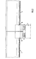
- FIG. 1 - The structure shown in Figures 1 and 2 for an elevated Fahrweg entry - the several meters high support 1 is shown in Fig. 2 only hinted and completely omitted in Fig. 1 - consists essentially of a prestressed concrete support tube 2 and manufactured as separate components Track plates 3, said track plates are not formed in the same length as the prestressed concrete support tube 2, but are made of individual plate segments with a correspondingly shorter length. This allows, regardless of the production of these track plates 3 as reinforced concrete slabs or, as shown, as a sheet steel construction, a considerably simpler processing of the track plates.
- the complete separation of the track plates and the actual longitudinal member allows a design of the longitudinal member as, at least approximately symmetrical and thus only small imbalance pointing pipe, which can therefore be prepared by means of spun concrete production.
- the entire superstructure, the track plate 3 shows, together with the supporting longitudinal tube, which previously had usually a trapezoidal, upwardly enlarged cross-section, has been manufactured as a one-piece component, which made a meaningful spun concrete production almost impossible.
- this component had to be handled as a whole regardless of its type of production.
- the separation according to the invention of the track plates from the prestressed concrete support tubes 2 enables a very simple road surface elevation in curves, as shown in FIGS. 3 to 5.
- the prestressed concrete support tube is rotated about its longitudinal axis, that is, for example, correspondingly twisted, is concreted to the bracket 10.
- the slope is not constant within a precast guideway with 20 m - 31 m in length must remain the same, but the plate segments each of about 6.20 m could have different inclinations.
- Fig. 7 shows an enlarged section through a prestressed concrete support tube 2, in which the arranged in different circular cylindrical planes 18 and 19 prestressing steels 20 and 21 are also indicated.
- the prestressing steels are in the lower, the support shoulders 4 remote, half of the prestressed concrete support tube 2 packed more tightly, possibly also stronger, in order to achieve increased reinforcement in this lower particularly stressed to train by the weight-loaded area.
- This asymmetrical distribution of the reinforcement can now be exploited in conjunction with an asymmetrical distribution of the support ribs 22 for stiffening the molded sheet 23 within a spun concrete mold 24 according to FIG.
Landscapes
- Engineering & Computer Science (AREA)
- Mechanical Engineering (AREA)
- Architecture (AREA)
- Civil Engineering (AREA)
- Structural Engineering (AREA)
- Manufacturing & Machinery (AREA)
- Chemical & Material Sciences (AREA)
- Ceramic Engineering (AREA)
- Manufacturing Of Tubular Articles Or Embedded Moulded Articles (AREA)
- Railway Tracks (AREA)
- Control Of Vehicles With Linear Motors And Vehicles That Are Magnetically Levitated (AREA)
- On-Site Construction Work That Accompanies The Preparation And Application Of Concrete (AREA)
Claims (11)
- Chemin carrossable pour des chemins de transport terrestre, de préférence pour des voies à lévitation magnétique, par exemple TRANSRAPID, comprenant des supports de chemin carrossable en éléments préfabriqués disposés sur des infrastructures fabriquées dans du béton fait sur place ou en éléments préfabriqués, qui présentent au moins un longeron en béton précontraint, armé et creux, et avec des plaques de chemin carrossable (3) continues transversalement à la voie de circulation, débordant des deux côtés du longeron en béton précontraint et fabriquées sous la forme de composants séparés, caractérisé en ce que le longeron en béton précontraint est réalisé sous la forme d'un tuyau support en béton précontraint (2) fabriqué au moyen de la fabrication en béton projeté et sensiblement cylindrique avec des épaulements de support (4) supérieurs plats pour les plaques de chemin carrossable (3), les épaulements de support (4) étant réalisés par des nervures de renforcement (6) débordant sur le côté.
- Chemin carrossable selon la revendication 1, caractérisé en ce que les plaques de chemin carrossable (3) sont des plaques de béton armées.
- Chemin carrossable selon la revendication 1, caractérisé en ce que les plaques de chemin carrossable (3) sont des constructions en tôle d'acier.
- Chemin carrossable selon l'une quelconque des revendications 1 à 3, caractérisé en ce que la plaque de chemin carrossable (3) de chaque support de chemin carrossable est constituée d'une pluralité de plaques individuelles courtes dans le sens du chemin carrossable qui sont fixées de façon espacée sur les tuyaux supports en béton armé (2).
- Chemin carrossable selon l'une quelconque des revendications 1 à 4, caractérisé en ce que, dans le cas d'un guidage de chemin carrossable en surélévation, le tuyau support en béton précontraint (2) disposé au centre par rapport à la plaque de chemin carrossable (3) est doté de consoles d'appui (10) bétonnées ultérieurement pour la fixation sur des piliers d'appui (1).
- Chemin carrossable selon la revendication 5, caractérisé en ce que des douilles filetées (8) sont enrobées dans les tuyaux supports en béton précontraint (2) pour le vissage de barres d'ancrage (9) s'engageant dans une console d'appui (10).
- Chemin carrossable selon la revendication 5 ou 6, caractérisé en ce que les tuyaux supports en béton précontraint (2) présentent une surface rendue rugueuse au moins dans la zone portante des consoles d'appui (10).
- Chemin carrossable selon l'une quelconque des revendications 1 à 7, caractérisé en ce que, pour sa surélévation latérale dans des parties en courbe, des clavettes intermédiaires (12) et éventuellement des plaques d'espacement (13) sont introduites entre l'épaulement de support (4) des tuyaux supports en béton précontraint (2) et les plaques de chemin carrossable (3).
- Chemin carrossable selon l'une quelconque des revendications 1 à 8, caractérisé en ce que, pour sa surélévation latérale dans des parties en courbe, les tuyaux supports en béton précontraint (2) sont bétonnés sur les consoles d'appui (10) tournés autour de leur axe longitudinal.
- Chemin carrossable selon l'une quelconque des revendications 1 à 9, caractérisé en ce que les tuyaux supports en béton précontraint (2) sont dotés dans leur zone inférieure, opposée aux épaulements de support (4), d'une armature renforcée à base d'aciers précontraints (20, 21) plus épais et/ou compactés de façon plus dense.
- Moule de béton projeté pour la fabrication d'un tuyau support en béton précontraint pour un chemin carrossable présentant des plaques de chemin carrossable (3) selon la revendication 1, le tuyau support en béton précontraint (2) étant réalisé de façon sensiblement cylindrique et avec des épaulements d'appui (4) supérieurs plats pour les plaques de chemin carrossable, qui sont formées par des nervures de renforcement (6) latérales, débordant du moule de tuyau sensiblement cylindrique, et le tuyau en béton précontraint étant doté dans sa zone inférieure, opposée aux épaulements de support (4), d'une armature renforcée à base d'aciers précontraints (20, 21) plus épais et/ou compactés de façon plus dense, caractérisé en ce que la tôle profilée (23) déterminant la forme extérieure du tuyau support en béton précontraint (2, 2') est dotée de nervures d'appui (22) disposées et réparties de façon asymétrique autour de l'axe de rotation (25) de telle sorte que, en liaison avec la répartition dissymétrique des aciers précontraints (20, 21), le déséquilibre occasionné par la proportion de béton élevée dans la zone des nervures de renforcement (6) est compensé.
Applications Claiming Priority (3)
| Application Number | Priority Date | Filing Date | Title |
|---|---|---|---|
| DE19919703A DE19919703C2 (de) | 1999-04-30 | 1999-04-30 | Fahrweg für Transrapid |
| DE19919703 | 1999-04-30 | ||
| CA002323977A CA2323977A1 (fr) | 1999-04-30 | 2000-10-19 | Passage pour reseaux de transport terrestre |
Publications (3)
| Publication Number | Publication Date |
|---|---|
| EP1048784A2 EP1048784A2 (fr) | 2000-11-02 |
| EP1048784A3 EP1048784A3 (fr) | 2000-12-27 |
| EP1048784B1 true EP1048784B1 (fr) | 2006-05-24 |
Family
ID=25682175
Family Applications (1)
| Application Number | Title | Priority Date | Filing Date |
|---|---|---|---|
| EP00108482A Expired - Lifetime EP1048784B1 (fr) | 1999-04-30 | 2000-04-19 | Voie pour circulation à lévitation magétique, par exemple TRANSRAPID |
Country Status (3)
| Country | Link |
|---|---|
| EP (1) | EP1048784B1 (fr) |
| CA (1) | CA2323977A1 (fr) |
| DE (1) | DE19919703C2 (fr) |
Families Citing this family (24)
| Publication number | Priority date | Publication date | Assignee | Title |
|---|---|---|---|---|
| DE10038851A1 (de) | 2000-08-04 | 2002-02-14 | Boegl Max Bauunternehmung Gmbh | Verfahren zum Herstellen einer Verbindungsstelle an einem Fahrweg |
| US6951433B2 (en) | 2000-08-04 | 2005-10-04 | Dieter Reichel | Device for nonpositively fixing a bracket to a supporting base body |
| CZ2003628A3 (cs) | 2000-09-12 | 2003-08-13 | Max Bögl Bauunternehmung GmbH & Co. KG | Nosník vysokorychlostního vozidla vedeného ve stopě |
| KR20020031674A (ko) * | 2000-10-23 | 2002-05-03 | 추후제출 | 경량궤도차용 차도 |
| DE20220631U1 (de) * | 2001-02-12 | 2004-02-19 | Lichius, Lina | Fahrweg für spurgeführte Fahrzeuge |
| DE10110613B4 (de) * | 2001-03-06 | 2009-06-10 | Otmar Fahrion | Fahrwegsegment für eine Magnetschwebebahn |
| CN1143027C (zh) | 2001-09-07 | 2004-03-24 | 上海磁悬浮交通发展有限公司 | 高速轨道交通的轨道结构 |
| CN1128899C (zh) | 2001-09-21 | 2003-11-26 | 上海磁悬浮交通发展有限公司 | 高速轨道交通的轨道结构 |
| DE10215668A1 (de) * | 2002-04-10 | 2003-10-30 | Zueblin Ag | Fahrweg für Magnetschwebebahn |
| DE10217460C1 (de) * | 2002-04-19 | 2003-12-24 | Pfleiderer Infrastrukturt Gmbh | In Schleuderbeton hergestelltes Spannbetontragrohr, insbesondere für Fahrwege von Magnetschwebebahnen |
| WO2003102304A1 (fr) | 2002-05-28 | 2003-12-11 | Thyssenkrupp Technologies Ag | Voie de communication pour vehicules a sustentation magnetique |
| DE10228387B4 (de) * | 2002-06-25 | 2014-10-16 | Polygro Trading Ag | Behältersystem zum Transport und zur Lagerung hochradioaktiver Materialien |
| DE20210554U1 (de) * | 2002-07-08 | 2003-11-20 | Wilcken, Alexander von, 80939 München | Kopplungsvorrichtung, insbesondere für einen Fahrweg für eine Magnetschwebebahn, und Fahrweg für eine Magnetschwebebahn |
| DE10237176B4 (de) | 2002-08-14 | 2006-06-08 | Pfleiderer Infrastrukturtechnik Gmbh & Co. Kg | Fahrbahn für Magnetbahnzüge |
| DE10239661A1 (de) * | 2002-08-24 | 2004-03-18 | Walter Bau-Ag | Fahrweg in modularer Bauweise, inbesondere für eine Magnetbahn |
| DE10240808A1 (de) * | 2002-08-30 | 2004-03-11 | Walter Bau-Ag | Magnetbahnfahrweg aus Stahlträgern im Verbund mit Fahrwegelementen aus Betonfertigteilen |
| DE502004005750D1 (de) * | 2003-01-14 | 2008-01-31 | Baugesellschaft Friedrich Witt | Fahrbahn für magnetschwebebahnen und herstellungsverfahren dafür |
| DE10301897A1 (de) * | 2003-01-17 | 2004-07-29 | Ed. Züblin Ag | Exakte Lagerung der Betonfertigteilplatten des Fahrweges einer Magnetschwebebahn auf einem Träger |
| DE10353949A1 (de) | 2003-11-18 | 2005-06-16 | Max Bögl Bauunternehmung GmbH & Co. KG | Verfahren zum lagegenauen Aufstellen eines Trägers für einen Fahrweg und Fahrweg |
| DE102005011838A1 (de) * | 2005-03-15 | 2006-09-21 | Pfleiderer Europoles Gmbh & Co. Kg | Schilderbrücke |
| DE102005057380B4 (de) * | 2005-11-30 | 2009-12-03 | Walter Sobolewski | Röhrenartiger, hohler, fester Fahrwegträger |
| DE102010026586A1 (de) | 2010-07-08 | 2012-01-12 | Roland Lipp | Fahrbahn für eine Magnetschwebebahn |
| DE102010048819A1 (de) | 2010-10-20 | 2012-04-26 | Roland Lipp | Hochgeschwindigkeits-Fernverkehrssystem zum Transport von Personen und/oder Lasten |
| CN107756600B (zh) * | 2017-11-20 | 2024-05-24 | 上海师范大学 | 水泥管片圆弧面自动收水抹平装置 |
Family Cites Families (9)
| Publication number | Priority date | Publication date | Assignee | Title |
|---|---|---|---|---|
| GB561400A (en) * | 1942-11-09 | 1944-05-18 | Paul William Abeles | Improvements in reinforced concrete construction and in methods of, and apparatus for, their production |
| FR1045807A (fr) * | 1951-06-18 | 1953-12-01 | Procédés et appareils de fabrication d'éléments de construction en béton centrifugé et éléments ainsi obtenus | |
| DE1180387B (de) * | 1961-04-21 | 1964-10-29 | Johannes Doernen Fa | Metallene zweigleisige Eisenbahnbruecke |
| JPH01160610A (ja) * | 1987-12-18 | 1989-06-23 | Sumitomo Constr Co Ltd | 多角形中空コンクリート部材の製造用型枠装置 |
| JPH07113435B2 (ja) * | 1989-03-31 | 1995-12-06 | 中川ヒューム管工業株式会社 | 遠心成形コンクリート管 |
| DE4115936A1 (de) * | 1991-05-16 | 1992-11-19 | Dyckerhoff & Widmann Ag | Aus stahl- oder spannbeton bestehender traeger fuer einen fahrweg fuer magnetschwebefahrzeuge |
| FR2746824A1 (fr) * | 1996-03-27 | 1997-10-03 | Baudin Chateauneuf Sa | Caissons precontraints pour tablier de pont |
| DE19619866C2 (de) * | 1996-05-17 | 2003-10-02 | Boegl Max Bauunternehmung Gmbh | Fahrweg für Magnetbahnzüge |
| DE29809580U1 (de) * | 1998-05-28 | 1998-08-20 | Noell Stahl- und Maschinenbau GmbH, 97080 Würzburg | Fahrwegplatte für die Fahrbahn von Magnetbahnzügen |
-
1999
- 1999-04-30 DE DE19919703A patent/DE19919703C2/de not_active Expired - Fee Related
-
2000
- 2000-04-19 EP EP00108482A patent/EP1048784B1/fr not_active Expired - Lifetime
- 2000-10-19 CA CA002323977A patent/CA2323977A1/fr not_active Abandoned
Also Published As
| Publication number | Publication date |
|---|---|
| EP1048784A2 (fr) | 2000-11-02 |
| DE19919703C2 (de) | 2001-05-23 |
| DE19919703A1 (de) | 2000-11-16 |
| CA2323977A1 (fr) | 2002-04-19 |
| EP1048784A3 (fr) | 2000-12-27 |
Similar Documents
| Publication | Publication Date | Title |
|---|---|---|
| DE19919703C2 (de) | Fahrweg für Transrapid | |
| EP0381136B1 (fr) | Voie porteuse pour véhicules magnétiques | |
| EP2088244B1 (fr) | Pont en béton armé ou pont de construction composite et methode pour sa fabrication | |
| EP1317360B1 (fr) | Support | |
| WO2007033991A1 (fr) | Concept de tour | |
| DE2717869A1 (de) | Verfahren zum herstellen von bauteilen aus spannbeton | |
| EP2143843A2 (fr) | Auge composite en acier-béton formant tablier de pont et son procédé de fabrication | |
| DE10321047B4 (de) | Fahrbahn für Magnetschwebebahnen und Herstellungsverfahren dafür | |
| EP2959060B1 (fr) | Joint de chaussée | |
| DE2247609B1 (de) | Verfahren zum herstellen eines brueckenbauwerks aus spannbeton im abschnittsweisen freien vorbau | |
| DE2338926A1 (de) | Tragwerk einer schnellbahn | |
| DE102011102987A1 (de) | Das Taktschiebeverfahren mit Stützweitenreduzierung für Strassen- und Bahnbrücken mit Plattenbalkenquerschnitt | |
| EP2029813B1 (fr) | Procédé de fabrication d'un pont à pièces préfabriquées en forme de segments et pont à pièces préfabriquées en forme de segments | |
| EP2166149B2 (fr) | Unité de pièce de structure de voie ferrée | |
| DE2216484A1 (de) | Verfahren zum herstellen einer fahrbahn aus stahl- oder spannbeton | |
| DE3343721A1 (de) | Hoher, freistehender schornstein oder turm aus stahlbeton-fertigteilen | |
| EP1597434B1 (fr) | Piste pour trains a sustentation magnetique, et son procede de production | |
| DE19831984C2 (de) | Bauteil mit externen Spanngliedern | |
| DE3738291C2 (fr) | ||
| EP2431524A1 (fr) | Superstructure de pont dotée d'une armature externe | |
| AT527835B1 (de) | Verfahren zur Herstellung einer vorgespannten Brücke | |
| DE19944783A1 (de) | Feste-Fahrbahn-System | |
| EP1008691B1 (fr) | Pont en béton à précontrainte extérieure | |
| DE19719409C2 (de) | Tragelement und Verfahren zum Herstellen eines Tragelementes | |
| EP0878581A1 (fr) | Elément de support et procédé de fabrication d'un élément de support |
Legal Events
| Date | Code | Title | Description |
|---|---|---|---|
| PUAI | Public reference made under article 153(3) epc to a published international application that has entered the european phase |
Free format text: ORIGINAL CODE: 0009012 |
|
| AK | Designated contracting states |
Kind code of ref document: A2 Designated state(s): AT BE CH CY DE DK ES FI FR GB GR IE IT LI LU MC NL PT SE |
|
| AX | Request for extension of the european patent |
Free format text: AL;LT;LV;MK;RO;SI |
|
| PUAL | Search report despatched |
Free format text: ORIGINAL CODE: 0009013 |
|
| RIC1 | Information provided on ipc code assigned before grant |
Free format text: 7E 01B 25/00 A, 7E 01D 2/00 B, 7B 28B 21/30 B |
|
| AK | Designated contracting states |
Kind code of ref document: A3 Designated state(s): AT BE CH CY DE DK ES FI FR GB GR IE IT LI LU MC NL PT SE |
|
| AX | Request for extension of the european patent |
Free format text: AL;LT;LV;MK;RO;SI |
|
| 17P | Request for examination filed |
Effective date: 20010606 |
|
| AKX | Designation fees paid |
Free format text: AT BE CH CY DE DK ES FI FR GB GR IE IT LI LU MC NL PT SE |
|
| AXX | Extension fees paid |
Free format text: AL PAYMENT 20010606;LT PAYMENT 20010606;LV PAYMENT 20010606;MK PAYMENT 20010606;RO PAYMENT 20010606;SI PAYMENT 20010606 |
|
| 17Q | First examination report despatched |
Effective date: 20031114 |
|
| GRAP | Despatch of communication of intention to grant a patent |
Free format text: ORIGINAL CODE: EPIDOSNIGR1 |
|
| RTI1 | Title (correction) |
Free format text: TRACK FOR MAGNETIC LEVITATION TRAFFIC, FOR EXAMPLE TRANSRAPID |
|
| GRAS | Grant fee paid |
Free format text: ORIGINAL CODE: EPIDOSNIGR3 |
|
| GRAA | (expected) grant |
Free format text: ORIGINAL CODE: 0009210 |
|
| AK | Designated contracting states |
Kind code of ref document: B1 Designated state(s): AT BE CH CY DE DK ES FI FR GB GR IE IT LI LU MC NL PT SE |
|
| AX | Request for extension of the european patent |
Extension state: AL LT LV MK RO SI |
|
| PG25 | Lapsed in a contracting state [announced via postgrant information from national office to epo] |
Ref country code: IT Free format text: LAPSE BECAUSE OF FAILURE TO SUBMIT A TRANSLATION OF THE DESCRIPTION OR TO PAY THE FEE WITHIN THE PRESCRIBED TIME-LIMIT;WARNING: LAPSES OF ITALIAN PATENTS WITH EFFECTIVE DATE BEFORE 2007 MAY HAVE OCCURRED AT ANY TIME BEFORE 2007. THE CORRECT EFFECTIVE DATE MAY BE DIFFERENT FROM THE ONE RECORDED. Effective date: 20060524 Ref country code: FI Free format text: LAPSE BECAUSE OF FAILURE TO SUBMIT A TRANSLATION OF THE DESCRIPTION OR TO PAY THE FEE WITHIN THE PRESCRIBED TIME-LIMIT Effective date: 20060524 Ref country code: IE Free format text: LAPSE BECAUSE OF FAILURE TO SUBMIT A TRANSLATION OF THE DESCRIPTION OR TO PAY THE FEE WITHIN THE PRESCRIBED TIME-LIMIT Effective date: 20060524 |
|
| REG | Reference to a national code |
Ref country code: GB Ref legal event code: FG4D Free format text: NOT ENGLISH |
|
| REG | Reference to a national code |
Ref country code: CH Ref legal event code: EP |
|
| REG | Reference to a national code |
Ref country code: IE Ref legal event code: FG4D Free format text: LANGUAGE OF EP DOCUMENT: GERMAN |
|
| REF | Corresponds to: |
Ref document number: 50012800 Country of ref document: DE Date of ref document: 20060629 Kind code of ref document: P |
|
| PG25 | Lapsed in a contracting state [announced via postgrant information from national office to epo] |
Ref country code: SE Free format text: LAPSE BECAUSE OF FAILURE TO SUBMIT A TRANSLATION OF THE DESCRIPTION OR TO PAY THE FEE WITHIN THE PRESCRIBED TIME-LIMIT Effective date: 20060824 Ref country code: DK Free format text: LAPSE BECAUSE OF FAILURE TO SUBMIT A TRANSLATION OF THE DESCRIPTION OR TO PAY THE FEE WITHIN THE PRESCRIBED TIME-LIMIT Effective date: 20060824 |
|
| PG25 | Lapsed in a contracting state [announced via postgrant information from national office to epo] |
Ref country code: ES Free format text: LAPSE BECAUSE OF FAILURE TO SUBMIT A TRANSLATION OF THE DESCRIPTION OR TO PAY THE FEE WITHIN THE PRESCRIBED TIME-LIMIT Effective date: 20060904 |
|
| GBT | Gb: translation of ep patent filed (gb section 77(6)(a)/1977) |
Effective date: 20060905 |
|
| PG25 | Lapsed in a contracting state [announced via postgrant information from national office to epo] |
Ref country code: PT Free format text: LAPSE BECAUSE OF FAILURE TO SUBMIT A TRANSLATION OF THE DESCRIPTION OR TO PAY THE FEE WITHIN THE PRESCRIBED TIME-LIMIT Effective date: 20061024 |
|
| LTIE | Lt: invalidation of european patent or patent extension |
Effective date: 20060524 |
|
| REG | Reference to a national code |
Ref country code: IE Ref legal event code: FD4D |
|
| PLBE | No opposition filed within time limit |
Free format text: ORIGINAL CODE: 0009261 |
|
| STAA | Information on the status of an ep patent application or granted ep patent |
Free format text: STATUS: NO OPPOSITION FILED WITHIN TIME LIMIT |
|
| NLS | Nl: assignments of ep-patents |
Owner name: RAIL.ONE GMBH Effective date: 20070131 |
|
| 26N | No opposition filed |
Effective date: 20070227 |
|
| EN | Fr: translation not filed | ||
| REG | Reference to a national code |
Ref country code: GB Ref legal event code: 732E |
|
| REG | Reference to a national code |
Ref country code: CH Ref legal event code: PL |
|
| BERE | Be: lapsed |
Owner name: PFLEIDERER INFRASTRUKTURTECHNIK G.M.B.H. & CO. KG Effective date: 20070430 |
|
| PG25 | Lapsed in a contracting state [announced via postgrant information from national office to epo] |
Ref country code: CH Free format text: LAPSE BECAUSE OF NON-PAYMENT OF DUE FEES Effective date: 20070430 Ref country code: LI Free format text: LAPSE BECAUSE OF NON-PAYMENT OF DUE FEES Effective date: 20070430 |
|
| PG25 | Lapsed in a contracting state [announced via postgrant information from national office to epo] |
Ref country code: BE Free format text: LAPSE BECAUSE OF NON-PAYMENT OF DUE FEES Effective date: 20070430 |
|
| PG25 | Lapsed in a contracting state [announced via postgrant information from national office to epo] |
Ref country code: GR Free format text: LAPSE BECAUSE OF FAILURE TO SUBMIT A TRANSLATION OF THE DESCRIPTION OR TO PAY THE FEE WITHIN THE PRESCRIBED TIME-LIMIT Effective date: 20060825 Ref country code: FR Free format text: LAPSE BECAUSE OF FAILURE TO SUBMIT A TRANSLATION OF THE DESCRIPTION OR TO PAY THE FEE WITHIN THE PRESCRIBED TIME-LIMIT Effective date: 20070309 |
|
| PG25 | Lapsed in a contracting state [announced via postgrant information from national office to epo] |
Ref country code: AT Free format text: LAPSE BECAUSE OF NON-PAYMENT OF DUE FEES Effective date: 20070419 |
|
| PG25 | Lapsed in a contracting state [announced via postgrant information from national office to epo] |
Ref country code: FR Free format text: LAPSE BECAUSE OF FAILURE TO SUBMIT A TRANSLATION OF THE DESCRIPTION OR TO PAY THE FEE WITHIN THE PRESCRIBED TIME-LIMIT Effective date: 20060524 |
|
| PG25 | Lapsed in a contracting state [announced via postgrant information from national office to epo] |
Ref country code: MC Free format text: LAPSE BECAUSE OF NON-PAYMENT OF DUE FEES Effective date: 20070430 |
|
| PG25 | Lapsed in a contracting state [announced via postgrant information from national office to epo] |
Ref country code: LU Free format text: LAPSE BECAUSE OF NON-PAYMENT OF DUE FEES Effective date: 20070419 Ref country code: CY Free format text: LAPSE BECAUSE OF FAILURE TO SUBMIT A TRANSLATION OF THE DESCRIPTION OR TO PAY THE FEE WITHIN THE PRESCRIBED TIME-LIMIT Effective date: 20060524 |
|
| PGFP | Annual fee paid to national office [announced via postgrant information from national office to epo] |
Ref country code: DE Payment date: 20100427 Year of fee payment: 11 Ref country code: NL Payment date: 20100421 Year of fee payment: 11 |
|
| PGFP | Annual fee paid to national office [announced via postgrant information from national office to epo] |
Ref country code: GB Payment date: 20100401 Year of fee payment: 11 |
|
| REG | Reference to a national code |
Ref country code: DE Ref legal event code: R119 Ref document number: 50012800 Country of ref document: DE |
|
| REG | Reference to a national code |
Ref country code: DE Ref legal event code: R119 Ref document number: 50012800 Country of ref document: DE |
|
| REG | Reference to a national code |
Ref country code: NL Ref legal event code: V1 Effective date: 20111101 |
|
| GBPC | Gb: european patent ceased through non-payment of renewal fee |
Effective date: 20110419 |
|
| PG25 | Lapsed in a contracting state [announced via postgrant information from national office to epo] |
Ref country code: NL Free format text: LAPSE BECAUSE OF NON-PAYMENT OF DUE FEES Effective date: 20111101 |
|
| PG25 | Lapsed in a contracting state [announced via postgrant information from national office to epo] |
Ref country code: GB Free format text: LAPSE BECAUSE OF NON-PAYMENT OF DUE FEES Effective date: 20110419 |
|
| PG25 | Lapsed in a contracting state [announced via postgrant information from national office to epo] |
Ref country code: DE Free format text: LAPSE BECAUSE OF NON-PAYMENT OF DUE FEES Effective date: 20111031 |