EP0381852B1 - Dispositif pour joindre des rails de guidage - Google Patents
Dispositif pour joindre des rails de guidage Download PDFInfo
- Publication number
- EP0381852B1 EP0381852B1 EP89123710A EP89123710A EP0381852B1 EP 0381852 B1 EP0381852 B1 EP 0381852B1 EP 89123710 A EP89123710 A EP 89123710A EP 89123710 A EP89123710 A EP 89123710A EP 0381852 B1 EP0381852 B1 EP 0381852B1
- Authority
- EP
- European Patent Office
- Prior art keywords
- guide
- guide rail
- flange
- displays
- strap
- Prior art date
- Legal status (The legal status is an assumption and is not a legal conclusion. Google has not performed a legal analysis and makes no representation as to the accuracy of the status listed.)
- Expired - Lifetime
Links
Images

Classifications
-
- B—PERFORMING OPERATIONS; TRANSPORTING
- B66—HOISTING; LIFTING; HAULING
- B66B—ELEVATORS; ESCALATORS OR MOVING WALKWAYS
- B66B7/00—Other common features of elevators
- B66B7/02—Guideways; Guides
- B66B7/023—Mounting means therefor
- B66B7/026—Interconnections
Definitions
- the invention relates to a device for connecting the guide rails of lifts, with a centering device, for guiding a connecting rail in alignment with an already placed guide rail.
- DD-PS 92 525 a device for connecting guide rails has become known, in which at the joints of the guide rails at the lower end of the guide in the flange and in the web grooves and at the upper end of the guide also in the flange and in the web matching springs are milled.
- a tab with all-round tapered bevels is welded onto the flange of the lower guide rail end, which fits into a pocket-shaped connecting shoe welded onto the flange of the upper guide rail end.
- the bevelled tab on the lower part serves as a demonstration for the precisely milled end grooves and tongues, whereby the connecting shoe of the upper guide rail part is inserted over the tab and guided on all sides into the correct aligned position.
- One driven into a keyway milled in the tab and in the connecting shoe Locking element secures the two guide rail parts in their final working position.
- a disadvantage of this device for connecting guide rails is that both the tab and the connecting shoe have to be welded to the flange of the guide rail. This can result in thermal stresses and distortions, which have a negative impact on the running quality of the elevator car.
- the wedge tracks at least that in the connecting shoe, are to be produced for locking the two ends of the guide rail before the connecting shoe is welded to the flange of the guide rail. This means that the welded-on parts must match the milled grooves and tongues as well as the milled keyways.
- the invention is based on the object of proposing a device for the simultaneous and precise alignment of elevator modules and guide rails and for connecting the guide rails, in which the two rail ends automatically, precisely align during assembly, and in which no connecting parts are to be welded to the guide rails .
- the advantages achieved by the invention are essentially to be seen in the fact that the screwed lashing with the necessary guide devices can be produced by commercially available flat profiles or by bent sheet metal parts, the fastening holes for the screwing both in the guide rail parts and in the tab parts in accordance with the teachings in the factory can be drilled.
- the tabs of two opposite guide rails screwed to the lower rail joint serve as a guide for the lower ends of the upper ones Guide rails so that the beveled retaining tabs as well as the side flanged guide flanges of the U-shaped guide tabs center the upper shaft module for assembly when lowering on all sides.
- the last centering of the guide rails is additionally facilitated by the fact that the tongue and groove arranged on the end face have chamfered edges.
- Another advantage is that the guide rails do not experience any thermal stress or warping due to welding.
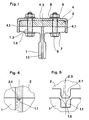
- 1, 2, 3, 4 and 5, 1 denotes the upper end of a lower guide rail.
- a groove 1.1 is provided at least in the web 1.2 for receiving a protruding spring 2.1 of an upper guide rail 2.
- the groove 1.1 and the tongue 2.1 have bevelled edges 1.5 and 2.5 on both long sides.
- four fastening holes 1.4 are provided, for example, on which holes of a holding bracket 3 and a guide bracket 4 fit.
- the retaining tab 3 is made of flat material and has, for example, eight fastening holes and, at the upper end, a bevel 3.1 serving as a guide for a subsequent guide rail 2.
- the guide bracket 4 also has eight corresponding fastening holes and is bent from sheet metal in a U-shape with two flanges 4.1 and a web 4.3.
- the flanges 4.1 of the guide plate 4 laterally encompass the retaining plate 3 and the flange 1.3 of the guide rail 1 or 2.
- the two flanges 4.1 are separated from the web 4.3 to a certain length and slightly bent outwards and form on both Sides of a guide tab 4.4 with the bevels 4.2 as a lateral centering when installing a subsequent guide rail 2.
- the two ends of the guide rails 1; 2 are butted together with screws 5, swash plates 7, locking washers 8 and nuts 6 with the aid of the holding plate 3 and the guide plate 4 and firmly connected to one another.
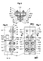
- FIGS. 6, 7 and 8 show a further embodiment variant of a guide rail joint, in which no U-shaped guide tabs are used.
- the retaining tab 3 is of the same design as the guide rail joint according to FIGS. 1, 2 and 3, while two guide tabs 4; 14 out two angularly bent sheets are made and are arranged on both sides of the web 1.2 of the guide rail 1.
- a first leg 4.1; 14.1 of the guide bracket 4, 14 lies flat on the web 1.2 of the guide rail 1 and the second leg 4.3; 14.3 lies flat against the slightly inclined inner surface of the flange 1.3 of the guide rail 1.
- the first leg 4.1; 14.1 has a guide tab 4.4 slightly protruding outwards from the adjoining upper guide rail 2; 14.4 with a bevel 4.2; 14.2, while in the second leg 4.3; 14.3 two holes 4.5 matching the fastening holes 1.4 of the guide rail 1; 14.5 are arranged.
- Millings 4.6; 14.6 in the area of the holes 4.5; 14.5 of the guide plate 4; 14 serve to compensate for the inclination adapted to the flange 1.3 of the guide rail 1.
- the left and right bevels 4.2; 14.2 of the guide plate 4; 14 serve as lateral centering during assembly for the adjoining upper guide rail 2.
- the lower end of the adjoining upper guide rail 2 is pushed against the upper end of the lower guide rail 1 and firmly connected to it with screws 5, locking washers 8 and nuts 6.
- the device described above for connecting guide rails is attached to the upper ends of the guide rails 1 installed in shaft modules during factory assembly.
- the shaft modules themselves normally correspond approximately to the respective floor height.
- the retaining bracket 3 drilled according to the teachings and, according to FIGS. 1-3, the guide bracket 4 are placed together over the flange 1.3 of the guide rail 1 and with the four screws 5, swash plates 7, locking washers 8 provided in the example and nuts 6 screwed together or according to FIGS. 6-8, the retaining tab 3 with the left and right guide tabs 4; 14 screwed together with the provided four screws 5, safety washers 8 and nuts 6.
- a first shaft module is inserted and anchored in a building and further shaft modules are placed on the first one from above.
- the free ends of the retaining tabs 3 and the guide tabs 4; 14 center the upper shaft module when lowering, by the lower ends of the adjoining upper guide rails 2 on the one hand through the lateral guide tabs 4.4; 14.4, on the other hand, through the bevels 3.1 of the retaining tabs 3 of two opposite guide rails into the exact alignment of the lower guide rails 1.
- the groove 1.1 milled on the end face in the web 1.2 of the lower guide rails 1, together with the tongue 2.1 projecting on the end on the adjoining upper guide rails 2, serves as the final, exact centering of the guide rails 1; 2, or as a precise connection of the abutting guide surfaces of the guide rails 1; 2, whereby for better mutual centering of the end position of the guide rails 1; 2, the beveled edges 1.5 and 2.5 provided on both long sides of the groove 1.1 and tongue 2.1 serve.
- the upper guide rails 2 with the retaining tabs 3 or the guide tabs 4 are firmly connected with the aid of the screws 5, the locking washers 8 and the nuts 6.
- the guide rail connection described above has two main parts according to FIGS. 1-3 for manufacturing reasons, a retaining tab 3 and a retaining tab 3 and the flange of the guide rail 1; 2 guide tabs encompassing the side 4. It would be readily possible to connect these two tabs to one another and to provide a one-piece, U-shaped tab with the necessary guide bevels and flanges encompassing the guide rails laterally.
Landscapes
- Lift-Guide Devices, And Elevator Ropes And Cables (AREA)
- Joining Of Building Structures In Genera (AREA)
- Leg Units, Guards, And Driving Tracks Of Cranes (AREA)
Claims (6)
- Dispositif pour réunir les rails de guidage (1) d'ascenseurs, comportant un dispositif de centrage, pour le guidage d'un rail de raccordement (2) dans l'alignement d'un rail de guidage (1) déjà en place, caractérisé en ce qu'il est prévu, à l'extrémité des rails de guidage (1) d'un module d'ascenseur en place, une éclisse (3 ; 4) qui est apte à être vissée, est appliquée, au niveau de trois côtés, contre le rail de guidage (1), et présente, au niveau de l'extrémité prévue pour la fixation d'un rail de raccordement (2), des biseaux (3.1, 4.2) dirigés vers les rails de guidage (1), au niveau de la face arrière et des deux parties latérales, comme dispositif de centrage simultané en vue du guidage d'un module d'ascenseur pourvu de rails de raccordement (2) dans l'alignement du module d'ascenseur déjà en place pourvu de rails de guidage (1).
- Dispositif selon la revendication 1, caractérisé en ce que l'éclisse (3 ; 4) apte à être vissée et appliquée, au niveau de trois côtés, contre le rail de guidage présente une forme en U et entoure des deux côtés l'aile (1.3) du rail de guidage, étant précisé que les deux biseaux latéraux sont disposés au niveau des deux côtés entourant l'aile du rail de guidage.
- Dispositif selon la revendication 2, caractérisé en ce que l'éclisse comporte une éclisse de retenue (3) insérée dans une éclisse de guidage (4), étant précisé que celle-ci entoure latéralement l'éclisse de retenue (3) et l'aile (1.3) du rail de guidage (1), et que les biseaux latéraux (4.2) sont définis par des pattes de guidage (4.4) séparées de la face arrière et légèrement coudées vers l'extérieur.
- Dispositif selon la revendication 1, caractérisé en ce que l'éclisse apte à être vissée et appliquée, au niveau de trois côtés, contre le rail de guidage, comporte une éclisse de retenue (3) appliquée contre l'aile (1.3), située côté arrière, du rail de guidage (1), et des éclisses de guidage angulaires (4 ; 14) appliquées de part et d'autre de l'âme (1.2) du rail de guidage (1), étant précisé qu'une première branche (4.1 ; 14.1), pourvue de la patte de guidage (4.4 ; 14.4), légèrement coudée vers l'extérieur, de l'éclisse de guidage (4 ; 14) est appliquée contre l'âme (1.2) du rail de guidage (1), tandis que la seconde branche (4.3 ; 14.3) présente des trous de fixation (4.5 ; 14.5), est disposée sur la surface intérieure inclinée de l'aile (1.3) du rail de guidage (1) et est reliée à l'éclisse de retenue (3).
- Dispositif selon la revendication 4, caractérisé en ce que la seconde branche (4.3 ; 14.3) de l'éclisse de guidage (4 ; 14) présente, dans la zone des trous de fixation (4.5 ; 14.5), des parties fraisées (4.6 ; 14.6) destinées à compenser l'inclinaison de l'aile (1.3) du rail de guidage (1).
- Dispositif selon l'une des revendications 1 à 5, caractérisé en ce qu'un dispositif de centrage disposé au niveau des faces frontales des rails de guidage inférieur et supérieur (1 ; 2) et formé d'une rainure (1.1) et d'une languette associée (2.1), présente des arêtes biseautées (1.5 ; 2.5).
Applications Claiming Priority (4)
| Application Number | Priority Date | Filing Date | Title |
|---|---|---|---|
| CH479/89 | 1989-02-10 | ||
| CH47989 | 1989-02-10 | ||
| CH280589 | 1989-07-27 | ||
| CH2805/89 | 1989-07-27 |
Publications (2)
| Publication Number | Publication Date |
|---|---|
| EP0381852A1 EP0381852A1 (fr) | 1990-08-16 |
| EP0381852B1 true EP0381852B1 (fr) | 1993-10-27 |
Family
ID=25684692
Family Applications (1)
| Application Number | Title | Priority Date | Filing Date |
|---|---|---|---|
| EP89123710A Expired - Lifetime EP0381852B1 (fr) | 1989-02-10 | 1989-12-22 | Dispositif pour joindre des rails de guidage |
Country Status (7)
| Country | Link |
|---|---|
| EP (1) | EP0381852B1 (fr) |
| JP (1) | JPH0696436B2 (fr) |
| AU (1) | AU631179B2 (fr) |
| DE (1) | DE58906034D1 (fr) |
| ES (1) | ES2047651T3 (fr) |
| HK (1) | HK9795A (fr) |
| IL (1) | IL93314A (fr) |
Families Citing this family (19)
| Publication number | Priority date | Publication date | Assignee | Title |
|---|---|---|---|---|
| EP1056678B1 (fr) * | 1997-10-01 | 2002-04-17 | Wittur AG | Cage d'ascenseur premontee |
| TR200201599T2 (tr) * | 1999-12-23 | 2006-08-21 | S. A. De Vera (Savera) | Asansör rayları birleştirme sistemi. |
| ES2161635B1 (es) * | 1999-12-23 | 2002-09-01 | De Vera Savera Sa | Sistema de union de guias de ascensor |
| DE60329286D1 (de) * | 2003-07-15 | 2009-10-29 | Monteferro S P A | Positioniervorrichtung für die Führungsschienen von Aufzügen |
| CN1895982B (zh) * | 2005-07-13 | 2011-06-15 | 因温特奥股份公司 | 连接夹板 |
| EP1743863A1 (fr) * | 2005-07-13 | 2007-01-17 | Inventio Ag | Elément de connexion |
| ES2320949B1 (es) * | 2006-11-16 | 2010-03-09 | S.A. De Vera (Savera) | Sistema de union con autoalineado, para guias de ascensor. |
| JP2010173815A (ja) * | 2009-01-30 | 2010-08-12 | Toshiba Elevator Co Ltd | エレベータのガイドレール用目板 |
| ES2686907T3 (es) * | 2009-04-02 | 2018-10-22 | S.A. De Vera ( Savera) | Sistema de unión con autolineado, para guías de ascensor |
| CN102464252A (zh) * | 2010-11-17 | 2012-05-23 | 快速电梯有限公司 | 导轨连接件 |
| FI125131B (fi) * | 2012-04-10 | 2015-06-15 | Kone Corp | Hissin johteiden liitosvälineistö, hissin johteiden liitosjärjestely ja hissi |
| CN103159109A (zh) * | 2013-03-27 | 2013-06-19 | 莱芜钢铁集团有限公司 | 一种电梯导轨系统 |
| CN103466412B (zh) * | 2013-09-12 | 2016-06-08 | 张家港市通达电梯装璜有限公司 | 一种空心电梯导轨的接导件 |
| CN105382853B (zh) * | 2015-12-03 | 2017-06-20 | 重庆热谷机器人科技有限责任公司 | 机器人长距离导轨 |
| JP6215393B1 (ja) * | 2016-05-19 | 2017-10-18 | 東芝エレベータ株式会社 | エレベータのガイドレール構造 |
| WO2018163297A1 (fr) * | 2017-03-07 | 2018-09-13 | 三菱電機株式会社 | Rail de guidage d'ascenseur |
| ES2881548A1 (es) | 2020-05-27 | 2021-11-29 | S A De Vera Savera | Sistema de unión y centrado para guías de chapa hueca cerrada |
| CN114084773A (zh) | 2020-08-24 | 2022-02-25 | 奥的斯电梯公司 | 模块化电梯组件和导轨 |
| WO2022148529A1 (fr) * | 2021-01-05 | 2022-07-14 | Kone Corporation | Procédé d'alignement de rails-guides d'un ascenseur |
Family Cites Families (6)
| Publication number | Priority date | Publication date | Assignee | Title |
|---|---|---|---|---|
| DD92525A (fr) | ||||
| US3420337A (en) * | 1967-09-21 | 1969-01-07 | John E Magee | Rail fastener |
| US4023732A (en) * | 1975-03-03 | 1977-05-17 | Mathis Edmond J | Elevator rail clamp |
| US4079817A (en) * | 1976-11-16 | 1978-03-21 | Westinghouse Electric Corporation | Elevator system with fish plate for correcting an out-of-tolerance between guide dimension |
| US4345671A (en) * | 1980-03-12 | 1982-08-24 | Westinghouse Electric Corp. | Apparatus and method for installing elevator guide rails |
| US4577729A (en) * | 1984-12-05 | 1986-03-25 | Westinghouse Electric Corp. | Guide rail clamping assembly |
-
1989
- 1989-12-22 DE DE89123710T patent/DE58906034D1/de not_active Expired - Lifetime
- 1989-12-22 ES ES89123710T patent/ES2047651T3/es not_active Expired - Lifetime
- 1989-12-22 EP EP89123710A patent/EP0381852B1/fr not_active Expired - Lifetime
-
1990
- 1990-02-07 JP JP2028140A patent/JPH0696436B2/ja not_active Expired - Lifetime
- 1990-02-08 IL IL93314A patent/IL93314A/xx not_active IP Right Cessation
- 1990-02-09 AU AU49259/90A patent/AU631179B2/en not_active Expired
-
1995
- 1995-01-19 HK HK9795A patent/HK9795A/xx not_active IP Right Cessation
Also Published As
| Publication number | Publication date |
|---|---|
| IL93314A (en) | 1992-06-21 |
| AU631179B2 (en) | 1992-11-19 |
| ES2047651T3 (es) | 1994-03-01 |
| EP0381852A1 (fr) | 1990-08-16 |
| IL93314A0 (en) | 1990-11-29 |
| HK9795A (en) | 1995-01-27 |
| JPH0696436B2 (ja) | 1994-11-30 |
| JPH02239082A (ja) | 1990-09-21 |
| DE58906034D1 (de) | 1993-12-02 |
| AU4925990A (en) | 1990-08-16 |
Similar Documents
| Publication | Publication Date | Title |
|---|---|---|
| EP0381852B1 (fr) | Dispositif pour joindre des rails de guidage | |
| EP0411314B1 (fr) | Cadre de support pour voie pour véhicule déplaçable sur rails, notamment pour train à lévitation magnétique | |
| EP2099971B1 (fr) | Ensemble de connecteur de joint de rail | |
| DE2540267C3 (de) | Tragwerk für eine zerlegbare Brücke | |
| DE60034433T2 (de) | Einrichtung und verfahren zum führungsschieneneinbau | |
| EP0763494B1 (fr) | Procédé et dispositif pour fixer un rail de guidage à un support de rail | |
| EP1977870B1 (fr) | Dispositif d'aide pour relier deux poutres en bois à l'aide de vis | |
| AT512054B1 (de) | Temporäre hilfsbrücken-abstützeinrichtung für gleisabschnitte | |
| DE1964637A1 (de) | Schienenverbindung fuer Haengebahnen | |
| WO2002075051A2 (fr) | Piste de circulation pour vehicules guides sur piste | |
| EP1026321A1 (fr) | Raccord en acier pour traverses de chemins de fer, notamment traverses en béton précontraint pour aiguillages | |
| EP0153463A2 (fr) | Elément de plaque en profilés creux | |
| DE9408678U1 (de) | Klemmvorrichtung zum Verziehen von Schienen | |
| DE3518811A1 (de) | Knotenplatte | |
| DE102021206322B4 (de) | Schienenprofilsystem und Verfahren zum Herstellen eines Schienenprofilsystems | |
| DE19814129C1 (de) | Halte- und Einstellelement für ein Fahrwegelement | |
| DE19946053B4 (de) | Fahrzeugchassis-Baugruppe mit Hauptlangträgern und Querträgern | |
| DE2823269A1 (de) | Stahlrammpfahl | |
| DE3928398C2 (fr) | ||
| DE2506124C3 (de) | Zerlegbare Brücke | |
| WO2023110417A1 (fr) | Montage d'un rail creux dans une cage d'ascenseur d'un système d'ascenseur | |
| DE3339243A1 (de) | Vorrichtung zum verbinden von schalungselementen | |
| EP1136172A2 (fr) | Appareil pour aligner et souder des tôles d'une structure allongée à section transversale du type en caisson, en particulier le pont principal d'une grue | |
| CH685788A5 (de) | Fassadenverkleidung, Verankerungselement für dieselbe und Werkzeug zum Befestigen und Lösen von Platten. | |
| EP0755847A1 (fr) | Connection de structures assemblées |
Legal Events
| Date | Code | Title | Description |
|---|---|---|---|
| PUAI | Public reference made under article 153(3) epc to a published international application that has entered the european phase |
Free format text: ORIGINAL CODE: 0009012 |
|
| AK | Designated contracting states |
Kind code of ref document: A1 Designated state(s): BE CH DE ES FR GB LI NL |
|
| 17P | Request for examination filed |
Effective date: 19901120 |
|
| 17Q | First examination report despatched |
Effective date: 19920430 |
|
| GRAA | (expected) grant |
Free format text: ORIGINAL CODE: 0009210 |
|
| AK | Designated contracting states |
Kind code of ref document: B1 Designated state(s): BE CH DE ES FR GB LI NL |
|
| REF | Corresponds to: |
Ref document number: 58906034 Country of ref document: DE Date of ref document: 19931202 |
|
| ET | Fr: translation filed | ||
| GBT | Gb: translation of ep patent filed (gb section 77(6)(a)/1977) |
Effective date: 19931129 |
|
| REG | Reference to a national code |
Ref country code: ES Ref legal event code: FG2A Ref document number: 2047651 Country of ref document: ES Kind code of ref document: T3 |
|
| PLBE | No opposition filed within time limit |
Free format text: ORIGINAL CODE: 0009261 |
|
| STAA | Information on the status of an ep patent application or granted ep patent |
Free format text: STATUS: NO OPPOSITION FILED WITHIN TIME LIMIT |
|
| 26N | No opposition filed | ||
| REG | Reference to a national code |
Ref country code: GB Ref legal event code: IF02 |
|
| PGFP | Annual fee paid to national office [announced via postgrant information from national office to epo] |
Ref country code: CH Payment date: 20080317 Year of fee payment: 19 |
|
| PGFP | Annual fee paid to national office [announced via postgrant information from national office to epo] |
Ref country code: NL Payment date: 20081216 Year of fee payment: 20 |
|
| PGFP | Annual fee paid to national office [announced via postgrant information from national office to epo] |
Ref country code: ES Payment date: 20081217 Year of fee payment: 20 |
|
| PGFP | Annual fee paid to national office [announced via postgrant information from national office to epo] |
Ref country code: FR Payment date: 20081212 Year of fee payment: 20 |
|
| PGFP | Annual fee paid to national office [announced via postgrant information from national office to epo] |
Ref country code: DE Payment date: 20081219 Year of fee payment: 20 |
|
| PGFP | Annual fee paid to national office [announced via postgrant information from national office to epo] |
Ref country code: GB Payment date: 20081216 Year of fee payment: 20 |
|
| PGFP | Annual fee paid to national office [announced via postgrant information from national office to epo] |
Ref country code: BE Payment date: 20090130 Year of fee payment: 20 |
|
| REG | Reference to a national code |
Ref country code: CH Ref legal event code: PL |
|
| PG25 | Lapsed in a contracting state [announced via postgrant information from national office to epo] |
Ref country code: LI Free format text: LAPSE BECAUSE OF NON-PAYMENT OF DUE FEES Effective date: 20081231 Ref country code: CH Free format text: LAPSE BECAUSE OF NON-PAYMENT OF DUE FEES Effective date: 20081231 |
|
| BE20 | Be: patent expired |
Owner name: *INVENTIO A.G. Effective date: 20091222 |
|
| REG | Reference to a national code |
Ref country code: GB Ref legal event code: PE20 Expiry date: 20091221 |
|
| PG25 | Lapsed in a contracting state [announced via postgrant information from national office to epo] |
Ref country code: NL Free format text: LAPSE BECAUSE OF EXPIRATION OF PROTECTION Effective date: 20091222 |
|
| NLV7 | Nl: ceased due to reaching the maximum lifetime of a patent |
Effective date: 20091222 |
|
| REG | Reference to a national code |
Ref country code: ES Ref legal event code: FD2A Effective date: 20091223 |
|
| PG25 | Lapsed in a contracting state [announced via postgrant information from national office to epo] |
Ref country code: GB Free format text: LAPSE BECAUSE OF EXPIRATION OF PROTECTION Effective date: 20091221 Ref country code: ES Free format text: LAPSE BECAUSE OF EXPIRATION OF PROTECTION Effective date: 20091223 |