EP0382939A2 - Hydraulisches Aufzugssystem - Google Patents
Hydraulisches Aufzugssystem Download PDFInfo
- Publication number
- EP0382939A2 EP0382939A2 EP89123634A EP89123634A EP0382939A2 EP 0382939 A2 EP0382939 A2 EP 0382939A2 EP 89123634 A EP89123634 A EP 89123634A EP 89123634 A EP89123634 A EP 89123634A EP 0382939 A2 EP0382939 A2 EP 0382939A2
- Authority
- EP
- European Patent Office
- Prior art keywords
- hydraulic
- elevator car
- car
- elevator
- pattern
- Prior art date
- Legal status (The legal status is an assumption and is not a legal conclusion. Google has not performed a legal analysis and makes no representation as to the accuracy of the status listed.)
- Granted
Links
Images

Classifications
-
- B—PERFORMING OPERATIONS; TRANSPORTING
- B66—HOISTING; LIFTING; HAULING
- B66B—ELEVATORS; ESCALATORS OR MOVING WALKWAYS
- B66B1/00—Control systems of elevators in general
- B66B1/24—Control systems with regulation, i.e. with retroactive action, for influencing travelling speed, acceleration, or deceleration
- B66B1/28—Control systems with regulation, i.e. with retroactive action, for influencing travelling speed, acceleration, or deceleration electrical
- B66B1/285—Control systems with regulation, i.e. with retroactive action, for influencing travelling speed, acceleration, or deceleration electrical with the use of a speed pattern generator
Definitions
- the invention relates in general to elevator systems, and more specifically to elevator systems in which movement of an elevator car is responsive to movement of the plunger of a hydraulic jack.
- first and second vertical lanes of indicia such as cams, establish slowdown distances relative to each floor, one for each travel direction, third and fourth vertical lanes of indicia alternately notch a floor selector, to eliminate false actuation of the selector due to contact bounce, and a fifth lane of indicia mount landing cams, which are also used when re-leveling is necessary.
- Each vertical lane of indicia requires a vertical tape in the hatchway which adds substantially to the initial cost of an elevator system, as well as to maintenance costs and thus it would be desirable and it is an object of the present invention, to reduce the number of such lanes.
- the slowdown and landing indicia are used to control a hydraulic elevator valve, which typically includes up level, up stop, down level and down stop solenoids, as well as check and relief valves.
- the solenoids initiate preset speeds as the elevator car approaches and stops at a target floor. It would be desirable and is another object of the present invention to be able to control the speed, acceleration, and deceleration of a hydraulic elevator based upon car positional information which continuously indicates car position, without requiring tapes or other positional indicating devices in the hatchway.
- the present invention is a new and improved hydraulic elevator system which detects and controls the quantity Q of hydraulic fluid transferred between a reservoir of such fluid and the cylinder of a hydraulic jack.
- the position of the elevator car is continuously determined from Q, as car position is directly proportional to the integral of Q.
- the car velocity is also continuously determined from Q, as car velocity is directly proportional to Q.
- the actual Q at any instant is compared with the desired Q to provide an error signal which forces Q to follow the desired pattern during a run of the elevator car to a target floor. With positional information continuously available, the distance of the car from the target floor is determined, eliminating the need for slowdown cams to initiate a preset speed pattern change.
- the positional information may be used to determine the distance-to-go to the target floor.
- the distance-to-go information may then be used to calculate all, or selected portions of, the speed pattern.
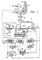
- FIG. 1 a hydraulic elevator system 10 constructed according to the teachings of the invention.
- the invention relates to any elevator system having a car 12 whose movement is responsive to the movement of a plunger 14 of a hydraulic jack 16, which also includes a cylinder 18.
- a conventional hydraulic elevator system 10 is illustrated in Figure 1, in which the elevator car 12, which includes a passenger cab 20 and sling (not shown), is mounted on the end of plunger 14.
- the invention also applies to roped hydros.
- Elevator car 12 is mounted for guided movement in the hatchway 22 of a structure or building 24 having floors to be served by the elevator car 12, with the first and second floors of building 24 being illustrated.
- Motive means for elevator car 12 includes a hydraulic circuit or system 26 comprising the hereinbefore mentioned jack assembly 16, a hydraulic power unit 28, suitable piping 30 which provides fluid flow communication between the power unit 28 and the jack assembly 16, and an electrical controller 32.
- Electrical controller 32 operates the power unit 28 to serve calls for elevator service generated from hall call buttons associated with the floors of building 24 and from car call buttons located in the elevator cab 20.
- the various hall call and car call buttons are not shown as they may be conventional.
- the hydraulic power unit 28 includes a supply or reservoir 34 of hydraulic fluid 36, such as hydraulic oil, a pump 38, such as a constant displacement pump, a motor 40 for driving pump 38, a source 42 of electrical potential, a line starter or contactor 44 for controllably connecting source 42 to motor 40, valve means 46 and a flowmeter 48.
- Valve means 46 includes first and second normally closed solenoid valves 50 and 52, respectively, and a variable-orifice valve 54 which may be controlled in response to a voltage applied thereto.
- Valve 50 is opened when elevator car 12 travels in the up direction
- valve 52 is opened when elevator car 12 travels in the down direction.
- Flowmeter 48 provides a measure of the flow rate of hydraulic fluid 36 flowing between hydraulic system 46 and hydraulic jack 16. In a preferred embodiment this measure is in the form of a pulse train Q whose rate is responsive to the rate of fluid flow.
- flowmeter 48 may be in the form of a turbine having vanes which rotate at a speed responsive to flow rate. Small magnets may be carried by the tips of the vanes which are detected by a magnetic pickup 56.
- the controller 32 includes supervisory control 58 which, among other things, energizes the up and down direction solenoid valves 50 and 52 when appropriate, means 60 for providing a signal responsive to the integral of Q, such as a counter, a multiplier function 61 for multiplying the integral of Q by a predetermined constant, means 62 for generating a pattern of desired car velocity, which may be a pattern of desired flow rate at any instant which will result in the desired car velocity, a frequency converter 64 for converting the pulse train Q to a voltage or value indicative of actual flow rate, a multiplier function 65 for multiplying Q by a predetermined constant, which is required if pattern generator 62 provides a speed pattern instead of a flow rate pattern, and a comparator and scaler 66 which provides the required voltage at any instant for operating valve 54 to cause the actual car velocity and rate-of-change of velocity to track the desired car velocity and rate-of-change of velocity.
- supervisory control 58 which, among other things, energizes the up and down direction solenoid valve
- the volume of hydraulic oil in the cylinder 18 is related to oil flow rate Q as follows:
- the length of the cylinder 18 occupied by the hydraulic oil is indicated by L, which also directly indicates the position of the elevator car 12, and the internal diameter of cylinder 18 is indicated by D.
- L The position L of the elevator car is equal to:
- Controller 32 regulates the speed of car 12 by monitoring the flow rate Q and it adjusts the variable orifice valve 54 until the actual flow rate Q matches the desired flow rate at any instant.
- the controller 32 also integrates the actual flow rate Q and calculates the position of the elevator car in the hatchway 22.
- controller 32 detects the frequency or rate of the pulses of the pulse train Q by applying them to the frequency converter 64.
- Converter 64 may be a frequency-to-voltage converter which provides a voltage having a magnitude which is directly responsive to the flow rate Q; or, converter 64 may be a read-only memory, with the frequency being used to access a look-up table which outputs a value responsive to flow rate. If pattern generator 62 provides a desired flow rate pattern, the output of converter 64 may be directly applied to comparator 66. If pattern generator 62 provides a desired car velocity, the output of converter 64 is multiplied by the constant K in the multiplier function 65 to obtain the actual velocity V of the elevator car 12.
- Comparator and scaler 66 compares the actual car speed V with the desired car speed PG and provides a control signal C having a magnitude necessary to control the orifice opening of valve 54 to cause the actual car speed to track the desired car speed.
- Pattern generator 62 may provide a flow pattern, or a speed pattern, as desired, which may be a predetermined pattern stored in a memory.
- the different parts of the pattern may be initiated according to time, and at fixed distances from a target floor.
- the pattern, or parts thereof may be calculated from car positional information generated according to the teachings of the invention.
- Figure 2 illustrates a typical pattern PG, which may be a flow rate pattern, or a speed pattern. For purposes of example, it will be assumed to be a speed pattern.
- Pattern PG is initiated by supervisory control 58 at time t0 and from time t0 to time t1 the speed pattern provides a smooth, jerk limited transition 70 from zero velocity to a constant acceleration rate.
- the speed increases along portion 72 until approaching the desired constant speed at time t2, where a transition 74 occurs between constant acceleration at time t2 and constant speed at time t3.
- the pattern remains at constant speed during a portion 76 until the car 12 reaches a point where deceleration must be initiated to make a normal stop at a target floor, which occurs at time t4.
- a transition 78 smoothly blends from constant velocity to constant deceleration at time t5, and a constant velocity portion 80 continues until a landing cam 84 at the target floor, shown in Figure 1, is detected at time t6 by either switch 1DL or switch 1UL, carried by the elevator car 12.
- Switch 1DL will make the initial contact with cam 84 in the up travel direction, and switch 1UL will make the initial contact in the down travel direction.
- Switches 1DL and 1UL are landing and re-leveling switches, as described in the hereinbefore mentioned U.S. Patent 4,469,199, which patent is hereby incorporated into the specification by reference.
- a transition 82 then occurs which smoothly blends the constant deceleration to zero speed at time t7.
- pattern portions 70, 72, 74, 76 and 78 are normally time based, and portions 80 and 82 are distance based.
- All of pattern PG may be calculated using the car positional information developed by the invention; or portions thereof may be calculated, such as the distance based portion 80, as desired.
- U.S. Patent 4,470,482 which is assigned to the same assignee as the present application, teaches a calculated speed pattern based upon car positional information, and this patent is hereby incorporated into the specification of the present application by reference.
- the car positional information is conveniently generated from signal Q by counter 60, which, as shown in Figure 3, integrates Q. Multiplying the count on counter 60 in the supervisory control by the constant K, provides the car position L. This information may be used to calculate the time based portions of the pattern, and this information may be used, along with the position of the target floor, to determine distance-to-go, which is used in the calculation of the distance based portion 80 of the speed pattern PG.
- the elevator controller 32 can tailor a speed pattern for each floor for optimum smoothness and efficiency of elevator service, taking into account the location of the car, the length of the run, the distance between floors, the load in the elevator car, the direction of travel, the temperature of the hydraulic fluid 36, and the like. Speed, acceleration, and deceleration may all be selected and changed to suit the present conditions.
- the normal slowdown cam lanes and floor selector notching lanes are not required, thus reducing the initial cost of the elevator system, as well as reducing maintenance costs.
Landscapes
- Engineering & Computer Science (AREA)
- Automation & Control Theory (AREA)
- Elevator Control (AREA)
- Fluid-Pressure Circuits (AREA)
- Types And Forms Of Lifts (AREA)
- Valve Device For Special Equipments (AREA)
- Vehicle Body Suspensions (AREA)
- Percussive Tools And Related Accessories (AREA)
- Forklifts And Lifting Vehicles (AREA)
- Load-Engaging Elements For Cranes (AREA)
Applications Claiming Priority (2)
| Application Number | Priority Date | Filing Date | Title |
|---|---|---|---|
| US07/310,553 US4932502A (en) | 1989-02-15 | 1989-02-15 | Hydraulic elevator system |
| US310553 | 1994-09-22 |
Publications (3)
| Publication Number | Publication Date |
|---|---|
| EP0382939A2 true EP0382939A2 (de) | 1990-08-22 |
| EP0382939A3 EP0382939A3 (de) | 1991-11-27 |
| EP0382939B1 EP0382939B1 (de) | 1994-08-31 |
Family
ID=23203033
Family Applications (1)
| Application Number | Title | Priority Date | Filing Date |
|---|---|---|---|
| EP89123634A Expired - Lifetime EP0382939B1 (de) | 1989-02-15 | 1989-12-21 | Hydraulisches Aufzugssystem |
Country Status (10)
| Country | Link |
|---|---|
| US (1) | US4932502A (de) |
| EP (1) | EP0382939B1 (de) |
| JP (1) | JPH02239071A (de) |
| AT (1) | ATE110691T1 (de) |
| CA (1) | CA2010089A1 (de) |
| DE (1) | DE68917901T2 (de) |
| ES (1) | ES2063806T3 (de) |
| FI (1) | FI92999C (de) |
| HU (1) | HU213711B (de) |
| RU (1) | RU1779235C (de) |
Cited By (5)
| Publication number | Priority date | Publication date | Assignee | Title |
|---|---|---|---|---|
| EP0957060A1 (de) * | 1998-05-14 | 1999-11-17 | Leistritz Aktiengesellschaft | Hydroseilaufzug |
| WO2000046138A1 (de) * | 1999-02-05 | 2000-08-10 | Wittur Ag | Verfahren und vorrichtung zur steuerung eines hydraulischen aufzugs |
| WO2003068653A3 (de) * | 2002-02-12 | 2003-12-18 | Bucher Hydraulics Ag | Vorrichtung zur steuerung und/oder regelung eines aufzugs |
| DE102007005021A1 (de) * | 2007-02-01 | 2008-08-14 | Tsg Technische Service Gesellschaft Mbh | Verbesserte Prüfverfahren für Hydraulikaufzüge |
| DE102008022415A1 (de) * | 2008-05-06 | 2009-11-12 | TÜV Rheinland Industrie Service GmbH | Absinkverhinderungsvorrichtung |
Families Citing this family (9)
| Publication number | Priority date | Publication date | Assignee | Title |
|---|---|---|---|---|
| ES2046329T3 (es) * | 1988-12-16 | 1994-02-01 | Gmv Martini S.P.A. | Sistema elevador hidraulico. |
| US5040639A (en) * | 1990-01-31 | 1991-08-20 | Kawasaki Jukogyo Kabushiki Kaisha | Elevator valve apparatus |
| US5072648A (en) * | 1990-06-04 | 1991-12-17 | Caterpillar Industrial Inc. | Control system for a fluid operated jack |
| TW346475B (en) * | 1997-02-06 | 1998-12-01 | Beringer Hydraulik Ag | Method and apparatus for controlling hydraulic elevator |
| DE50002755D1 (de) * | 1999-08-25 | 2003-08-07 | Bucher Hydraulics Ag Neuheim | Hydraulischer aufzug mit einem als gegengewicht wirkenden druckspeicher und verfahren zum steuern und regeln eines solchen aufzugs |
| US9347554B2 (en) * | 2013-03-14 | 2016-05-24 | Caterpillar Inc. | Hydrostatic drive system |
| US20150198245A1 (en) * | 2014-01-13 | 2015-07-16 | Caterpillar Paving Products Inc. | Hydraulic Drive System |
| US20150369261A1 (en) * | 2014-06-18 | 2015-12-24 | Caterpillar Paving Products Inc. | Hydraulic drive system |
| CN107076173B (zh) * | 2014-08-14 | 2019-11-15 | 费斯托股份有限两合公司 | 促动器控制器以及用于控制促动器的运动的方法 |
Family Cites Families (16)
| Publication number | Priority date | Publication date | Assignee | Title |
|---|---|---|---|---|
| US3570243A (en) * | 1968-12-09 | 1971-03-16 | Mobility Systems Inc | Hydraulic actuator control system |
| US3977497A (en) * | 1975-02-26 | 1976-08-31 | Armor Elevator Company, Inc. | Hydraulic elevator drive system |
| DE2509228C3 (de) * | 1975-03-04 | 1981-01-22 | Maschinenfabrik Augsburg-Nuernberg Ag, 8500 Nuernberg | Elektro-hydraulischer Antrieb für Hebezeuge |
| JPS54162353A (en) * | 1978-06-13 | 1979-12-22 | Toshiba Corp | Hydraulic circuit for driving cargo handling apparatus |
| JPS56122774A (en) * | 1980-02-26 | 1981-09-26 | Oirudoraibu Kogyo Kk | Oil pressure elevator |
| US4311212A (en) * | 1980-07-09 | 1982-01-19 | Elevator Equipment Co. | Valve control system |
| IT1138425B (it) * | 1981-06-16 | 1986-09-17 | Stigler Otis S P A | Complesso elettro-fluidodinamico per l'azionamento di una cabina di un impianto ascensore |
| US4469199A (en) * | 1982-06-10 | 1984-09-04 | Westinghouse Electric Corp. | Elevator system |
| US4470482A (en) * | 1982-12-02 | 1984-09-11 | Westinghouse Electric Corp. | Speed pattern generator for an elevator car |
| EP0162931A1 (de) * | 1983-07-28 | 1985-12-04 | Siminor S.A. | Hydraulische Aufzüge |
| JPS6169674A (ja) * | 1984-09-11 | 1986-04-10 | 株式会社東芝 | 油圧エレベ−タの制御装置 |
| JPS6167674A (ja) * | 1984-09-11 | 1986-04-07 | Yanmar Diesel Engine Co Ltd | 農用トラクタ−のフレ−ム構造 |
| JPS6210299A (ja) * | 1985-07-05 | 1987-01-19 | Fujisash Co | チタンまたはチタン合金の着色被膜形成方法 |
| JPH022960Y2 (de) * | 1985-07-05 | 1990-01-24 | ||
| JPS631683A (ja) * | 1986-06-20 | 1988-01-06 | 株式会社日立製作所 | 流体圧エレベ−タ |
| JPS6347279A (ja) * | 1986-08-13 | 1988-02-29 | 株式会社日立製作所 | 流体圧エレベ−タ |
-
1989
- 1989-02-15 US US07/310,553 patent/US4932502A/en not_active Expired - Fee Related
- 1989-12-21 DE DE68917901T patent/DE68917901T2/de not_active Expired - Fee Related
- 1989-12-21 AT AT89123634T patent/ATE110691T1/de not_active IP Right Cessation
- 1989-12-21 ES ES89123634T patent/ES2063806T3/es not_active Expired - Lifetime
- 1989-12-21 EP EP89123634A patent/EP0382939B1/de not_active Expired - Lifetime
-
1990
- 1990-02-13 JP JP2032278A patent/JPH02239071A/ja active Pending
- 1990-02-14 HU HU90795A patent/HU213711B/hu not_active IP Right Cessation
- 1990-02-14 FI FI900745A patent/FI92999C/fi not_active IP Right Cessation
- 1990-02-14 RU SU904743026A patent/RU1779235C/ru active
- 1990-02-14 CA CA002010089A patent/CA2010089A1/en not_active Abandoned
Cited By (9)
| Publication number | Priority date | Publication date | Assignee | Title |
|---|---|---|---|---|
| EP0957060A1 (de) * | 1998-05-14 | 1999-11-17 | Leistritz Aktiengesellschaft | Hydroseilaufzug |
| WO2000046138A1 (de) * | 1999-02-05 | 2000-08-10 | Wittur Ag | Verfahren und vorrichtung zur steuerung eines hydraulischen aufzugs |
| US6510923B1 (en) | 1999-02-05 | 2003-01-28 | Wittur Ag | Control method and apparatus for a hydraulic elevator using only load pressure data |
| WO2003068653A3 (de) * | 2002-02-12 | 2003-12-18 | Bucher Hydraulics Ag | Vorrichtung zur steuerung und/oder regelung eines aufzugs |
| DE102007005021A1 (de) * | 2007-02-01 | 2008-08-14 | Tsg Technische Service Gesellschaft Mbh | Verbesserte Prüfverfahren für Hydraulikaufzüge |
| DE102007005021B4 (de) * | 2007-02-01 | 2010-01-28 | Tsg Technische Service Gesellschaft Mbh | Verbessertes Prüfverfahren für Hydraulikaufzüge |
| AT504954A3 (de) * | 2007-02-01 | 2013-05-15 | Tsg Tech Service Gmbh | Verbessertes prüfverfahren für hydraulikaufzüge |
| AT504954B1 (de) * | 2007-02-01 | 2014-02-15 | Tsg Tech Service Gmbh | Verbessertes prüfverfahren für hydraulikaufzüge |
| DE102008022415A1 (de) * | 2008-05-06 | 2009-11-12 | TÜV Rheinland Industrie Service GmbH | Absinkverhinderungsvorrichtung |
Also Published As
| Publication number | Publication date |
|---|---|
| EP0382939A3 (de) | 1991-11-27 |
| CA2010089A1 (en) | 1990-08-15 |
| ATE110691T1 (de) | 1994-09-15 |
| HU900795D0 (en) | 1990-05-28 |
| ES2063806T3 (es) | 1995-01-16 |
| JPH02239071A (ja) | 1990-09-21 |
| HU213711B (en) | 1997-09-29 |
| FI900745A0 (fi) | 1990-02-14 |
| RU1779235C (ru) | 1992-11-30 |
| EP0382939B1 (de) | 1994-08-31 |
| FI92999B (fi) | 1994-10-31 |
| HUT53343A (en) | 1990-10-28 |
| US4932502A (en) | 1990-06-12 |
| DE68917901T2 (de) | 1995-02-16 |
| DE68917901D1 (de) | 1994-10-06 |
| FI92999C (fi) | 1995-02-10 |
Similar Documents
| Publication | Publication Date | Title |
|---|---|---|
| US4932502A (en) | Hydraulic elevator system | |
| US5421432A (en) | Method and apparatus for controlling and automatically correcting the command for deceleration/stoppage of the cage of a lift or a hoist in accordance with variations in the operating data of the system | |
| US5637841A (en) | Elevator system | |
| US6334511B1 (en) | Double-deck elevator control system | |
| EP3566993B1 (de) | Synchronisation basierend auf dem abstand einer magnetanordnung zu einer schiene | |
| FI101780B (fi) | Menetelmä ja laitteisto hissin hidastamiseksi | |
| US6050368A (en) | Procedure and apparatus for controlling the hoisting motor of an elevator | |
| CA1201831A (en) | Elevator system | |
| US4553640A (en) | Controller for elevator | |
| US5155305A (en) | Delayed start of elevator car deceleration and creep using VVVF technology | |
| CN1753824A (zh) | 升降机降落控制 | |
| US5848671A (en) | Procedure for stopping an elevator at a landing | |
| US4470482A (en) | Speed pattern generator for an elevator car | |
| JPH0446877B2 (de) | ||
| US5603390A (en) | Control system for an elevator | |
| US4469199A (en) | Elevator system | |
| KR100186381B1 (ko) | 엘리베이터의 동기위치 제어방법 | |
| EP4008667B1 (de) | Notfall-terminal-verzögerung in aufzugssystemen | |
| JPH0747444B2 (ja) | 流体圧エレベ−タ | |
| KR100295882B1 (ko) | 엘리베이터의 주행토크 보상방법 | |
| JPH02239076A (ja) | エレベータ制御装置 | |
| JPS60236984A (ja) | エレベ−タの制御装置 | |
| JPH0543146A (ja) | 油圧エレベーターの制御装置 | |
| JPH01127580A (ja) | 流体圧エレベータの制御装置 | |
| JPH10291743A (ja) | 油圧式エレベータ |
Legal Events
| Date | Code | Title | Description |
|---|---|---|---|
| PUAI | Public reference made under article 153(3) epc to a published international application that has entered the european phase |
Free format text: ORIGINAL CODE: 0009012 |
|
| AK | Designated contracting states |
Kind code of ref document: A2 Designated state(s): AT CH DE ES FR GB IT LI SE |
|
| PUAL | Search report despatched |
Free format text: ORIGINAL CODE: 0009013 |
|
| AK | Designated contracting states |
Kind code of ref document: A3 Designated state(s): AT CH DE ES FR GB IT LI SE |
|
| 17P | Request for examination filed |
Effective date: 19920520 |
|
| 17Q | First examination report despatched |
Effective date: 19930427 |
|
| GRAA | (expected) grant |
Free format text: ORIGINAL CODE: 0009210 |
|
| AK | Designated contracting states |
Kind code of ref document: B1 Designated state(s): AT CH DE ES FR GB IT LI SE |
|
| REF | Corresponds to: |
Ref document number: 110691 Country of ref document: AT Date of ref document: 19940915 Kind code of ref document: T |
|
| REF | Corresponds to: |
Ref document number: 68917901 Country of ref document: DE Date of ref document: 19941006 |
|
| ET | Fr: translation filed | ||
| ITF | It: translation for a ep patent filed | ||
| REG | Reference to a national code |
Ref country code: ES Ref legal event code: FG2A Ref document number: 2063806 Country of ref document: ES Kind code of ref document: T3 |
|
| EAL | Se: european patent in force in sweden |
Ref document number: 89123634.1 |
|
| PLBE | No opposition filed within time limit |
Free format text: ORIGINAL CODE: 0009261 |
|
| STAA | Information on the status of an ep patent application or granted ep patent |
Free format text: STATUS: NO OPPOSITION FILED WITHIN TIME LIMIT |
|
| 26N | No opposition filed | ||
| PGFP | Annual fee paid to national office [announced via postgrant information from national office to epo] |
Ref country code: SE Payment date: 19951113 Year of fee payment: 7 |
|
| PGFP | Annual fee paid to national office [announced via postgrant information from national office to epo] |
Ref country code: ES Payment date: 19951121 Year of fee payment: 7 |
|
| PGFP | Annual fee paid to national office [announced via postgrant information from national office to epo] |
Ref country code: GB Payment date: 19951127 Year of fee payment: 7 Ref country code: FR Payment date: 19951127 Year of fee payment: 7 |
|
| PGFP | Annual fee paid to national office [announced via postgrant information from national office to epo] |
Ref country code: DE Payment date: 19951130 Year of fee payment: 7 |
|
| PGFP | Annual fee paid to national office [announced via postgrant information from national office to epo] |
Ref country code: AT Payment date: 19951201 Year of fee payment: 7 |
|
| PGFP | Annual fee paid to national office [announced via postgrant information from national office to epo] |
Ref country code: CH Payment date: 19960320 Year of fee payment: 7 |
|
| PG25 | Lapsed in a contracting state [announced via postgrant information from national office to epo] |
Ref country code: GB Effective date: 19961221 Ref country code: AT Effective date: 19961221 |
|
| PG25 | Lapsed in a contracting state [announced via postgrant information from national office to epo] |
Ref country code: SE Effective date: 19961222 |
|
| PG25 | Lapsed in a contracting state [announced via postgrant information from national office to epo] |
Ref country code: ES Free format text: LAPSE BECAUSE OF THE APPLICANT RENOUNCES Effective date: 19961223 |
|
| PG25 | Lapsed in a contracting state [announced via postgrant information from national office to epo] |
Ref country code: LI Effective date: 19961231 Ref country code: CH Effective date: 19961231 |
|
| GBPC | Gb: european patent ceased through non-payment of renewal fee |
Effective date: 19961221 |
|
| REG | Reference to a national code |
Ref country code: CH Ref legal event code: PL |
|
| PG25 | Lapsed in a contracting state [announced via postgrant information from national office to epo] |
Ref country code: FR Effective date: 19970829 |
|
| PG25 | Lapsed in a contracting state [announced via postgrant information from national office to epo] |
Ref country code: DE Effective date: 19970902 |
|
| EUG | Se: european patent has lapsed |
Ref document number: 89123634.1 |
|
| REG | Reference to a national code |
Ref country code: FR Ref legal event code: ST |
|
| REG | Reference to a national code |
Ref country code: ES Ref legal event code: FD2A Effective date: 20010402 |
|
| PG25 | Lapsed in a contracting state [announced via postgrant information from national office to epo] |
Ref country code: IT Free format text: LAPSE BECAUSE OF NON-PAYMENT OF DUE FEES Effective date: 20051221 |