EP0383232B1 - Rechnergesteuertes Tomographiegerät - Google Patents
Rechnergesteuertes Tomographiegerät Download PDFInfo
- Publication number
- EP0383232B1 EP0383232B1 EP90102712A EP90102712A EP0383232B1 EP 0383232 B1 EP0383232 B1 EP 0383232B1 EP 90102712 A EP90102712 A EP 90102712A EP 90102712 A EP90102712 A EP 90102712A EP 0383232 B1 EP0383232 B1 EP 0383232B1
- Authority
- EP
- European Patent Office
- Prior art keywords
- projection
- slice
- projection data
- data
- slices
- Prior art date
- Legal status (The legal status is an assumption and is not a legal conclusion. Google has not performed a legal analysis and makes no representation as to the accuracy of the status listed.)
- Expired - Lifetime
Links
Images



Classifications
-
- A—HUMAN NECESSITIES
- A61—MEDICAL OR VETERINARY SCIENCE; HYGIENE
- A61B—DIAGNOSIS; SURGERY; IDENTIFICATION
- A61B6/00—Apparatus or devices for radiation diagnosis; Apparatus or devices for radiation diagnosis combined with radiation therapy equipment
- A61B6/02—Arrangements for diagnosis sequentially in different planes; Stereoscopic radiation diagnosis
- A61B6/03—Computed tomography [CT]
- A61B6/032—Transmission computed tomography [CT]
-
- A—HUMAN NECESSITIES
- A61—MEDICAL OR VETERINARY SCIENCE; HYGIENE
- A61B—DIAGNOSIS; SURGERY; IDENTIFICATION
- A61B6/00—Apparatus or devices for radiation diagnosis; Apparatus or devices for radiation diagnosis combined with radiation therapy equipment
- A61B6/02—Arrangements for diagnosis sequentially in different planes; Stereoscopic radiation diagnosis
- A61B6/027—Arrangements for diagnosis sequentially in different planes; Stereoscopic radiation diagnosis characterised by the use of a particular data acquisition trajectory, e.g. helical or spiral
-
- G—PHYSICS
- G06—COMPUTING OR CALCULATING; COUNTING
- G06T—IMAGE DATA PROCESSING OR GENERATION, IN GENERAL
- G06T12/00—Tomographic reconstruction from projections
- G06T12/10—Image preprocessing, e.g. calibration, positioning of sources or scatter correction
Definitions
- the present invention relates to a computerized tomographic (CT) apparatus utilizing radiation rays such as X-rays, and, more particularly, to a CT apparatus which performs helical scan to acquire projection data.
- CT computerized tomographic
- CT apparatuses of the above mentioned type recently become popular since they can scan a wide examining region of an object to be examined in a short period of time.
- One example of such CT apparatuses is a computerized tomographic apparatus utilizing a radiation source, disclosed in United States Patent No. 4,630,202.
- the helical scan is a system to move the object in a given direction by permitting the patient platform of a gantry assembly on which the object is placed to slide in the direction of the body axis of the object, and rotate an X-ray tube around the object to continuously scan it. If it is assumed that the object is fixed, the locus of the movement of the X-ray tube relative to the object forms a helix. The pitch of the helix corresponds to the moving velocity of patient platform. In the ordinary dynamic scan and multi-scan, with the object being fixed, the X-ray tube is always rotated within the same slice.
- projection data for one helical turn may be processed as one set of projection data for acquire one slice image.
- projection data for a projection angle of 0° differs from that for a projection angle of 360° by the distance corresponding to the pitch of the helix
- some inconsistency will naturally occur in image reconstruction. This is likely to cause an artifact such as a streak on a reconstructed slice image. This event becomes more prominent as the distance corresponding to the pitch of the helix is increased to speed up data acquisition.
- FIG. 1 is a block diagram of a first embodiment of an X-ray CT apparatus according to the present invention.
- a housing dome 1 which incorporates an X-ray tube, a detector and other components, has its center portion open cylindrically in the horizontal direction to define a scanning space 3.
- a detector array 5 which has many X-ray detectors arranged circumferentially.
- An X-ray tube 7 is disposed rotatable around the array 5. The X-ray tube 7 can be continuously rotated by using a slip ring.
- This scan system is a modification of a so-called fourth generation scan system which has detectors arranged circumferentially and an X-ray tube disposed rotatable inward of the detector arrangement.
- a gantry assembly 9 is connected to the front of the dome 1, and a patient platform 11 on which an object P is to be placed slides on the gantry assembly 9 to carry the object P into the scanning space 3.
- the X-ray tube 7 irradiates a fan-shaped X-ray onto the object P while rotating around the imaginary axis which passes the center of the space 3 and lies within the object P.
- the object P is scanned helically with X-rays.
- the detector array 5 detects the X-rays from the X-ray tube 7 which have penetrated the object P.
- the X-ray tube 7 is located outside the detector array 5, there are two detectors positioned along the radiation path of the X-rays, one closest to the tube 7 and the other opposite to the former one. In order to set the closest detector off the radiation path, therefore, the array 5 performs a nutation movement when X-rays are irradiated. Therefore, this system is called a nutation/rotation system.
- the helical scan can be easily realized. It is noted that even with the use of the so-called third generation and fourth generation scanning system in which the X-ray tube is not continuously rotated, the helical scan can be executed if the sliding of the patient platform is performed when X-ray is irradiated. Further, the helical scan can be executed with the use of the third generation scanning system having a slip ring.
- a detection signal from the detector array 5 is output from the dome 1 and is supplied to an interpolation circuit 13.
- This circuit 13 is also supplied with a signal from the dome 1, which represents the rotational velocity (rotational cycle ⁇ ) of the X-ray tube 7 as well as a signal from the gantry assembly 9, which represents the scanning position x(t) of the patient platform 11.
- the interpolation circuit 13 performs a pre-process, such as amplification, integration or D/A conversion, on the detection signal obtained by the detector array 5, thereby preparing projection data for each projection angle.
- the interpolation circuit 13 Based on the rotational velocity data of the X-ray tube 7 and the scanning position data of the patient platform 11, the interpolation circuit 13 performs an interpolation processing (to be described later) on the projection data acquired by the helical scan, and outputs interpolation data which is equivalent to the projection data acquired when the X-ray tube is rotated within the same slice of the object.
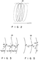
- the locus of the relative movement of the X-ray tube 7 to the object becomes helical as indicated by the broken line and the solid line in Fig. 2.
- This helical scan data does not therefore include projection data of one slice, so that the interpolation circuit 13 acquires, thought interpolation, projection data for 360° of a predetermined slice as indicated by the one-dot chain line as shown in Fig. 2 from the helical scan data for two turns indicated by the solid line.
- the projection data (interpolation data) from the interpolation circuit 13 is supplied to an image reconstruction circuit 15 where image reconstruction is performed.
- Reconstructed image data is supplied to and stored in an image store 17 which uses a recording medium such as a hard disk.
- the image data is also supplied to a display device 19 comprising a CRT which in turn displays a slice image or the like of the object P.
- the embodiment further comprises an input device 21 such as a keyboard through which a scanning position for specifying a slice for which interpolation data is to be acquired, is entered.
- the interpolation circuit 13 acquires interpolation data for each point on a slice 22 shown in Fig. 3 by performing linear interpolation of scan data of two adjoining points on the helix which have the same projection angle.
- Fig. 3 shows the locus of the X-ray tube which is also the locus of the detectors.
- projection data is obtained for each channel ⁇ .
- ⁇ is a channel pitch and i is the number of detector channels (1 ⁇ i ⁇ total number of detectors of the detector array 5).
- the interpolation circuit 13 calculates interpolation data P C ( ⁇ , ⁇ ) of a point C on the slice 22, using projection data P A ( ⁇ , ⁇ ) and P B ( ⁇ , ⁇ ) of two adjacent points A and B on the helix which have the same projection angle ⁇ as the point C and an interpolation ratio ⁇ as follows.
- P C ( ⁇ , ⁇ ) ⁇ P A ( ⁇ , ⁇ ) + (1 - ⁇ ) ⁇ P B ( ⁇ , ⁇ )
- first projection data of point A is obtained through interpolation from projection data of two points A′ and A ⁇ at the proximity of the point A.
- the interpolation ratio ⁇ in this case can be acquired from the projection angles of individual points A′, A, and A ⁇ .
- Scanning position XC (see Fig. 4) or the like corresponding to a target slice whose slice image is desired, is entered via the input device 21.
- the X-ray tube 7 is rotated at a given cycle ⁇ while sliding the patient platform 11 on which the object P is placed, at a constant velocity to carry the body P inside the scanning space 3, whereby the object P is helically scanned at a constant velocity.
- Helical scan data obtained by this helical scan is supplied, together with rotational cycle data of the X-ray tube 7 and scanning position data of the patient platform 11 from the gantry assembly 9, to the interpolation circuit 13.
- This circuit 13 performs aforementioned various pre-processes on the helical scan data to provide projection data, then performs interpolation of this projection data according to the aforementioned equation (2) to thereby acquire projection data of each projection angle in the slice 22 for each channel.
- the interpolation data is supplied to the image reconstruction circuit 15 where an image reconstruction is executed.
- the resultant image data is sent to, and stored in, the image store 17.
- This image data is also supplied to the display device 19 which, based on the interpolation data, displays the image of an arbitrary slice of the object.
- projection data on a desired slice can be interpolated from data of adjacent two points on a helix having the same projection angle in accordance with the distances between the two points and the desired slice. Accordingly, a slice image without artifact can be obtained. Even if the moving velocity of the patient platform and the rotational velocity of the X-ray tube are increased to ensure high helical scan, the aforementioned interpolation can be executed, thus preventing any artifact from occurring. Further, a spatial resolution in the moving direction of the patient platform 11 is increased, since the slice image of the arbitrary scanning position can be obtained.
- a second embodiment utilizing projection data formed of counter beams will be described.
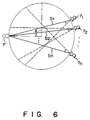
- the X-ray beam transmitted through the object in one direction and the counter X-ray beam transmitted through the object in the opposite direction have the same projection data. Therefore, as shown in Fig. 6, even if the X-ray tube 7′ does not irradiate the X-rays at the projection angle ⁇ , the projection data having the projection angle ⁇ can be obtained by the X-ray counter beams b 1 , b 2 , ... b n irradiated from the X-ray tubes 7 1 , 7 2 , ... 7 n .
- the block diagram of the second embodiment is the same as that of the first embodiment.
- the interpolation principle using the counter beams according to the second embodiment is shown in Fig. 7.
- the interpolation circuit 13 first calculates the projection data having the projection angle ⁇ from the counter beams b 1 , b 2 , ... b n . Then, the interpolation circuit 13 calculates interpolation data P C ( ⁇ , ⁇ ) of a point C on the slice 22, using projection data P A ( ⁇ , ⁇ ) and P′ B ( ⁇ , ⁇ ) of two scanning positions X' B and X A on the helix.
- the scanning position X' B corresponds to the middle point between the scanning position of the X-ray tube 71 and that of the X-ray tube 7n.
- the present invention is not limited to the above-described embodiment, but may be modified in various manners.
- radiation rays are not restricted to X-rays but may take another form, such as gamma rays.
- the practical method for realizing the helical scan is not limited to what has been described above, and the arrangement of the X-ray tube and detectors can be properly altered.
- the helical scan velocity determined in accordance with the moving velocity of the patient platform and rotational velocity of the X-ray tube is assumed to be constant in the embodiment, it does not necessarily be constant as long as this velocity is known, since the distance between points in different slices can be acquired on the basis of the scan velocity.
- the interpolation data for a slice is acquired from data of two points through a linear interpolation of the first order, it may be acquired through a nonlinear interpolation of the second order or greater or through a spline interpolation. Further, it is possible to interpolate the projection data of the desired slice from more than two data having the same projection angle.
- projection data equivalent to the one acquired when the same slice is scanned can be obtained by interpolating data obtained by the helical scan, thereby eliminating artifact which is the shortcoming of the conventional helical scan.
Landscapes
- Health & Medical Sciences (AREA)
- Life Sciences & Earth Sciences (AREA)
- Engineering & Computer Science (AREA)
- Medical Informatics (AREA)
- Physics & Mathematics (AREA)
- Radiology & Medical Imaging (AREA)
- Heart & Thoracic Surgery (AREA)
- High Energy & Nuclear Physics (AREA)
- Theoretical Computer Science (AREA)
- Nuclear Medicine, Radiotherapy & Molecular Imaging (AREA)
- Optics & Photonics (AREA)
- Pathology (AREA)
- Veterinary Medicine (AREA)
- Biomedical Technology (AREA)
- Biophysics (AREA)
- Molecular Biology (AREA)
- Surgery (AREA)
- Animal Behavior & Ethology (AREA)
- General Health & Medical Sciences (AREA)
- Public Health (AREA)
- General Physics & Mathematics (AREA)
- Pulmonology (AREA)
- Apparatus For Radiation Diagnosis (AREA)
- Analysing Materials By The Use Of Radiation (AREA)
Claims (6)
- Computerisiertes tomographisches Gerät mit:einer Abtasteinrichtung für die Bewegung eines Objekts in einer Richtung und für die Rotation von Bestrahlungsstrahlen in einer Ebene, die eine Bewegungsrichtung des Objekts schneidet, um hierdurch eine schraubenlinienförmige Abtastung des Objekts zu bewirken und hierdurch Projektionsdaten zu erzeugen, undeiner Interpolationseinrichtung (13) für die Interpolation von Projektionsdaten PC einer vorbestimmten Scheibe, die einen gegebenen Projektionswinkel aufweisen, in Abhängigkeit von zwei Projektionsdaten PA und PB von zwei Scheiben, die auf beiden Seiten der vorbestimmten Scheibe angeordnet sind und die den gegebenen Projektionswinkel aufweisen, und von Abständen zwischen den beiden Scheiben und der vorbestimmten Scheibe,dadurch gekennzeichnet, daß
die Interpolationseinrichtung (13) dann, wenn mindestens eine der beiden Scheiben keine Projektionsdaten PA mit dem gegebenen Projektionswinkel enthält, zuerst den gegebenen Projektionswinkel aufweisende Projektionsdaten PA von mindestens einer der beiden Scheiben in Abhängigkeit von zwei benachbarten Projektionsdaten PA' und PA" entlang einer schraubenlinienförmigen Abtastlinie, die sich von dem gegebenen Projektionswinkel unterscheidende Projektionswinkel aufweisen, und in Abhängigkeit von einem Abstand zwischen den den vorbestimmten Projektionswinkel aufweisenden Projektionsdaten PA von mindestens einer der beiden Scheiben und von PA' und PA" der beiden benachbarten Projektionsdaten, die sich von dem gegebenen Projektionswinkel unterscheidende Projektionswinkel aufweisen, interpoliert. - Gerät nach Anspruch 1, dadurch gekennzeichnet, daß die Interpolationseinrichtung (13) die Projektionsdaten PC(φ, θ) der vorbestimmten Scheibe, die einen Projektionswinkel φ und einen Detektorkanal θ aufweisen, in Abhängigkeit von den beiden Projektionsdaten PA(φ, θ) und PB(φ, θ) der beiden Scheiben, die den Projektionswinkel φ und den Detektorkanal θ aufweisen, in folgender Weise interpoliert:


- Gerät nach Anspruch 1 oder 2, dadurch gekennzeichnet, daß weiterhineine Bildrekonstruktionseinrichtung (15) für die Verarbeitung eines Ausgangssignals der Interpolationseinrichtung undeine Einrichtung (19) für die Anzeige eines Ausgangssignals der Bildrekonstruktionseinrichtung vorhanden sind.
- Verfahren zur Erzeugung eines Scheibenbilds eines Objekts, mit den Schritten:Bewegen des Objekts in einer Richtung, während Bestrahlungsstrahlen in einer Ebene gedreht werden, die eine Bewegungsrichtung des Objekts schneidet, um hierdurch eine schraubenlinienförmige Abtastung des Objekts durchzuführen und hierbei Daten für die schraubenlinienförmige Abtastung bereitzustellen,Bezeichnen einer gewünschten Scheibe des Objekts,Rekonstruieren eines Bilds der gewünschten Scheibe auf der Grundlage der Projektionsdaten, undInterpolieren von Projektionsdaten bei der gewünschten Scheibe, die einen gegebenen Projektionswinkel aufweisen, in Abhängigkeit von zwei Daten für die schraubenlinienförmige Abtastung an zwei Scheiben, die auf beiden Seiten der gewünschten Scheibe benachbart sind, und in Abhängigkeit von einem Abstand zwischen den beiden Scheiben und der gewünschten Scheibe,gekennzeichnet durch den weiteren Schritt, daß dann, wenn mindestens eine der beiden Scheiben keine Projektionsdaten PA mit dem gegebenen Projektionswinkel enthält, zuerst Projektionsdaten PA, von mindestens einer der beiden Scheiben, die den gegebenen Projektionswinkel aufweisen, in Abhängigkeit von zwei benachbarten Projektionsdaten PA' und PA" entlang einer schraubenlinienförmigen Abtastlinie, die sich von dem gegebenen Projektionswinkel unterscheidende Projektionswinkel aufweisen, und in Abhängigkeit von einem Abstand zwischen den Projektionsdaten PA von mindestens einer der beiden Scheiben, die den gegebenen Projektionswinkel aufweisen, und von jeweils PA' und PA" der beiden benachbarten Projektionsdaten, die sich von dem gegebenen Projektionswinkel unterscheidende Projektionswinkel aufweisen, interpoliert werden.
- Computerisiertes tomographisches Gerät mit:
einer Abtasteinrichtung für die Bewegung eines Objekts in einer Richtung und für die Drehung von Bestrahlungsstrahlen innerhalb einer Ebene, die eine Bewegungsrichtung des Objekts schneidet, um hierdurch eine schraubenlinienförmige Abtastung des Objekts durchzuführen und hierdurch Projektionsdaten bereitzustellen,
gekennzeichnet durcheine Einrichtung (13) für die Berechnung von Projektionsdaten P'B(φ, θ) einer ersten Scheibe, die einen Projektionswinkel φ und einen Detektorkanal θ aufweisen, unter Einsatz von Zählerstrahlen, undeine Einrichtung (13) für die Interpolation von Projektionsdaten PC(φ, θ) einer vorbestimmten Scheibe, die den Projektionswinkel φ und den Detektorkanal θ aufweisen, in Abhängigkeit von Projektionsdaten PA(φ, θ) einer zweiten Scheibe, die den Projektionswinkel φ und den Detektorkanal θ aufweisen, und den Projektionsdaten P'B(φ, θ) der ersten Scheibe. - Gerät nach Anspruch 5, dadurch gekennzeichnet, daß die Interpolationseinrichtung (13) die Projektionsdaten PC(φ, θ) in folgender Weise interpoliert:


Applications Claiming Priority (2)
| Application Number | Priority Date | Filing Date | Title |
|---|---|---|---|
| JP31016/89 | 1989-02-13 | ||
| JP1031016A JPH0728862B2 (ja) | 1989-02-13 | 1989-02-13 | Ct装置 |
Publications (3)
| Publication Number | Publication Date |
|---|---|
| EP0383232A2 EP0383232A2 (de) | 1990-08-22 |
| EP0383232A3 EP0383232A3 (de) | 1992-06-10 |
| EP0383232B1 true EP0383232B1 (de) | 1996-10-30 |
Family
ID=12319740
Family Applications (1)
| Application Number | Title | Priority Date | Filing Date |
|---|---|---|---|
| EP90102712A Expired - Lifetime EP0383232B1 (de) | 1989-02-13 | 1990-02-12 | Rechnergesteuertes Tomographiegerät |
Country Status (4)
| Country | Link |
|---|---|
| US (1) | US5073911A (de) |
| EP (1) | EP0383232B1 (de) |
| JP (1) | JPH0728862B2 (de) |
| DE (1) | DE69028999T2 (de) |
Families Citing this family (33)
| Publication number | Priority date | Publication date | Assignee | Title |
|---|---|---|---|---|
| US5485493A (en) * | 1988-10-20 | 1996-01-16 | Picker International, Inc. | Multiple detector ring spiral scanner with relatively adjustable helical paths |
| US5396418A (en) * | 1988-10-20 | 1995-03-07 | Picker International, Inc. | Four dimensional spiral volume imaging using fast retrace |
| US5262946A (en) * | 1988-10-20 | 1993-11-16 | Picker International, Inc. | Dynamic volume scanning for CT scanners |
| US5270923A (en) * | 1989-11-02 | 1993-12-14 | General Electric Company | Computed tomographic image reconstruction method for helical scanning using interpolation of partial scans for image construction |
| US5233518A (en) * | 1989-11-13 | 1993-08-03 | General Electric Company | Extrapolative reconstruction method for helical scanning |
| US5216601A (en) * | 1989-11-22 | 1993-06-01 | General Electric Company | Method for fan beam helical scanning using rebinning |
| US5208746A (en) * | 1989-11-22 | 1993-05-04 | General Electric Company | Method for helical scanning with a stationary detector using rebinning and splicing to create detector vertex projection sets |
| DE69028768T2 (de) * | 1990-04-04 | 1997-05-07 | Toshiba Kawasaki Kk | Verfahren und Vorrichtung zur rechnerunterstützten Erzeugung von Tomographien mittels schraubenförmiger Abtastbewegung |
| JPH0787835B2 (ja) * | 1990-06-27 | 1995-09-27 | 株式会社東芝 | X線断層撮影装置 |
| JPH04166138A (ja) * | 1990-10-31 | 1992-06-12 | Toshiba Corp | X線ct装置 |
| JP2607749B2 (ja) * | 1990-11-01 | 1997-05-07 | 株式会社東芝 | X線ct装置 |
| JP3047928B2 (ja) * | 1991-03-18 | 2000-06-05 | 株式会社日立メディコ | X線ct装置 |
| EP0504855B1 (de) * | 1991-03-20 | 1998-06-10 | Kabushiki Kaisha Toshiba | Röntgenstrahl-Computertomograph |
| IL98945A0 (en) * | 1991-07-24 | 1992-07-15 | Elscint Ltd | Multiple slice ct scanner |
| DE69223884T2 (de) * | 1991-09-12 | 1998-08-27 | Toshiba Kawasaki Kk | Verfahren und Vorrichtung zur Erzeugung von Röntgencomputertomogrammen und zum Erzeugen von Schattenbildern mittels spiralförmiger Abtastung |
| US5412562A (en) * | 1992-04-02 | 1995-05-02 | Kabushiki Kaisha Toshiba | Computerized tomographic imaging method and system for acquiring CT image data by helical dynamic scanning |
| US5224136A (en) * | 1992-06-30 | 1993-06-29 | General Electric Company | Helical scanning computed tomography apparatus with constrained tracking of the x-ray source |
| US5611026A (en) * | 1992-12-21 | 1997-03-11 | General Electric Company | Combining a priori data with partial scan data to project three dimensional imaging of arbitrary objects with computerized tomography |
| DE4321080C1 (de) * | 1993-06-24 | 1994-12-08 | Siemens Ag | Computertomograph mit Spiralabtastung |
| US5390112A (en) * | 1993-10-04 | 1995-02-14 | General Electric Company | Three-dimensional computerized tomography scanning method and system for imaging large objects with smaller area detectors |
| JPH08308827A (ja) * | 1995-05-24 | 1996-11-26 | Ge Yokogawa Medical Syst Ltd | 補間データ生成方法およびx線吸収係数急変面位置推定方法およびx線ct装置 |
| IL119714A0 (en) | 1996-11-28 | 1997-02-18 | Elscint Ltd | CT system with oblique image planes |
| US6097784A (en) * | 1998-09-30 | 2000-08-01 | Picker International, Inc. | 3D image reconstruction for helical partial cone beam data |
| US6104775A (en) * | 1998-10-29 | 2000-08-15 | Picker International, Inc. | 3D image reconstruction for helical partial cone beam scanners using wedge beam transform |
| DE10049380A1 (de) * | 2000-10-05 | 2002-04-11 | Philips Corp Intellectual Pty | Computertomograph mit kegelförmigem Strahlenbündel und helixförmiger Relativbewegung |
| US6790371B2 (en) * | 2001-04-09 | 2004-09-14 | Medtronic, Inc. | System and method for automated separation of blood components |
| US6597756B1 (en) * | 2002-06-19 | 2003-07-22 | Ge Medical Systems Global Technology Company, Llc | Methods and apparatus for multi-slice image reconstruction |
| US6977984B2 (en) * | 2003-10-07 | 2005-12-20 | Ge Medical Systems Global Technology Company, Llc | Methods and apparatus for dynamical helical scanned image production |
| DE102005053022A1 (de) * | 2005-11-07 | 2007-05-16 | Siemens Ag | Verfahren und Vorrichtung zur räumlichen Darstellung eines Untersuchungsbereichs eines Untersuchungsobjekts |
| JP2007236662A (ja) * | 2006-03-09 | 2007-09-20 | Ge Medical Systems Global Technology Co Llc | X線ct装置およびそのx線ct画像再構成方法、x線ct画像撮影方法。 |
| DE102006021372B4 (de) * | 2006-05-08 | 2010-02-04 | Siemens Ag | Verfahren zur Erstellung eines dreidimensionalen Bilddatensatzes eines Zielvolumens und medizinische Untersuchungseinrichtung |
| JP2012170736A (ja) * | 2011-02-23 | 2012-09-10 | Toshiba Corp | X線コンピュータ断層撮影装置 |
| WO2012123845A1 (en) * | 2011-03-15 | 2012-09-20 | Koninklijke Philips Electronics N.V. | Likelihood-based spectral data projection domain de-noising |
Family Cites Families (5)
| Publication number | Priority date | Publication date | Assignee | Title |
|---|---|---|---|---|
| US4280178A (en) * | 1979-08-24 | 1981-07-21 | General Electric Company | Computerized tomographic reconstruction method utilizing reflection |
| JPS59111738A (ja) * | 1982-12-16 | 1984-06-28 | 株式会社東芝 | X線断層撮影装置 |
| JPH0767445B2 (ja) * | 1985-10-14 | 1995-07-26 | 株式会社日立メディコ | X線ct装置 |
| US4789929A (en) * | 1987-05-14 | 1988-12-06 | Hitachi Medical Corporation | CT system for spirally scanning subject on a movable bed synchronized to X-ray tube revolution |
| NL8800321A (nl) * | 1988-02-10 | 1989-09-01 | Philips Nv | Computertomografie-inrichting voor spiraalsgewijze aftasting. |
-
1989
- 1989-02-13 JP JP1031016A patent/JPH0728862B2/ja not_active Expired - Lifetime
-
1990
- 1990-02-12 EP EP90102712A patent/EP0383232B1/de not_active Expired - Lifetime
- 1990-02-12 DE DE69028999T patent/DE69028999T2/de not_active Expired - Lifetime
-
1991
- 1991-05-28 US US07/707,276 patent/US5073911A/en not_active Expired - Lifetime
Also Published As
| Publication number | Publication date |
|---|---|
| US5073911A (en) | 1991-12-17 |
| DE69028999D1 (de) | 1996-12-05 |
| EP0383232A2 (de) | 1990-08-22 |
| JPH02211129A (ja) | 1990-08-22 |
| EP0383232A3 (de) | 1992-06-10 |
| DE69028999T2 (de) | 1997-06-05 |
| JPH0728862B2 (ja) | 1995-04-05 |
Similar Documents
| Publication | Publication Date | Title |
|---|---|---|
| US5073911A (en) | Computerized tomographic apparatus | |
| US6400789B1 (en) | On-line image reconstruction in helical CT scanners | |
| US4630202A (en) | Computerized tomographic apparatus utilizing a radiation source | |
| US5270923A (en) | Computed tomographic image reconstruction method for helical scanning using interpolation of partial scans for image construction | |
| EP0467532B1 (de) | Rechnergesteuertes Tomographiesystem | |
| US6944260B2 (en) | Methods and apparatus for artifact reduction in computed tomography imaging systems | |
| JP2509031B2 (ja) | 被作像体の断層撮影投影デ―タを取得する装置 | |
| US5233518A (en) | Extrapolative reconstruction method for helical scanning | |
| EP0430549B1 (de) | Spiralabtastrechnertomographie | |
| US5469486A (en) | Projection domain reconstruction method for helical scanning computed tomography apparatus with multi-column detector array employing overlapping beams | |
| US7154986B2 (en) | Tilted gantry helical cone-beam Feldkamp reconstruction for multislice CT | |
| US20070116175A1 (en) | System and method for reconstructing image by using straight-line trajectory scan | |
| US5513236A (en) | Image reconstruction for a CT system implementing a dual fan beam helical scan | |
| JP2006314856A (ja) | 物体の断層写真画像を発生するシステム及び体積測定式計算機式断層写真法装置 | |
| US6381297B1 (en) | High pitch reconstruction of multislice CT scans | |
| JPS6411297B2 (de) | ||
| JP3917684B2 (ja) | 物体の断層写真像を作成する方法及び装置 | |
| US4280178A (en) | Computerized tomographic reconstruction method utilizing reflection | |
| US5546439A (en) | Systems, methods and apparatus for incrementally reconstructing overlapped images in a CT system implementing a helical scan | |
| EP0200939B1 (de) | Emissionscomputertomographievorrichtung | |
| EP0450152B1 (de) | Verfahren und Vorrichtung zur rechnerunterstützten Erzeugung von Tomographien mittels schraubenförmiger Abtastbewegung | |
| EP0333857B1 (de) | Rechnergestützter röntgen-tomograph | |
| US7046758B1 (en) | X-ray CT apparatus | |
| US6463117B1 (en) | Methods and apparatus for tilted helical image reconstruction in CT imaging | |
| JPH04292147A (ja) | X線ct装置 |
Legal Events
| Date | Code | Title | Description |
|---|---|---|---|
| PUAI | Public reference made under article 153(3) epc to a published international application that has entered the european phase |
Free format text: ORIGINAL CODE: 0009012 |
|
| 17P | Request for examination filed |
Effective date: 19900212 |
|
| AK | Designated contracting states |
Kind code of ref document: A2 Designated state(s): DE FR NL |
|
| PUAL | Search report despatched |
Free format text: ORIGINAL CODE: 0009013 |
|
| AK | Designated contracting states |
Kind code of ref document: A3 Designated state(s): DE FR NL |
|
| 17Q | First examination report despatched |
Effective date: 19941229 |
|
| GRAG | Despatch of communication of intention to grant |
Free format text: ORIGINAL CODE: EPIDOS AGRA |
|
| GRAH | Despatch of communication of intention to grant a patent |
Free format text: ORIGINAL CODE: EPIDOS IGRA |
|
| GRAH | Despatch of communication of intention to grant a patent |
Free format text: ORIGINAL CODE: EPIDOS IGRA |
|
| GRAA | (expected) grant |
Free format text: ORIGINAL CODE: 0009210 |
|
| AK | Designated contracting states |
Kind code of ref document: B1 Designated state(s): DE FR NL |
|
| REF | Corresponds to: |
Ref document number: 69028999 Country of ref document: DE Date of ref document: 19961205 |
|
| ET | Fr: translation filed | ||
| PLBE | No opposition filed within time limit |
Free format text: ORIGINAL CODE: 0009261 |
|
| STAA | Information on the status of an ep patent application or granted ep patent |
Free format text: STATUS: NO OPPOSITION FILED WITHIN TIME LIMIT |
|
| 26N | No opposition filed | ||
| PGFP | Annual fee paid to national office [announced via postgrant information from national office to epo] |
Ref country code: DE Payment date: 20090206 Year of fee payment: 20 Ref country code: NL Payment date: 20090203 Year of fee payment: 20 |
|
| PGFP | Annual fee paid to national office [announced via postgrant information from national office to epo] |
Ref country code: FR Payment date: 20090213 Year of fee payment: 20 |
|
| NLV7 | Nl: ceased due to reaching the maximum lifetime of a patent |
Effective date: 20100212 |
|
| PG25 | Lapsed in a contracting state [announced via postgrant information from national office to epo] |
Ref country code: DE Free format text: LAPSE BECAUSE OF EXPIRATION OF PROTECTION Effective date: 20100212 |