EP0383246A2 - Procédé et appareil pour alimenter les flocons de fibres en quantité donnée - Google Patents
Procédé et appareil pour alimenter les flocons de fibres en quantité donnée Download PDFInfo
- Publication number
- EP0383246A2 EP0383246A2 EP90102745A EP90102745A EP0383246A2 EP 0383246 A2 EP0383246 A2 EP 0383246A2 EP 90102745 A EP90102745 A EP 90102745A EP 90102745 A EP90102745 A EP 90102745A EP 0383246 A2 EP0383246 A2 EP 0383246A2
- Authority
- EP
- European Patent Office
- Prior art keywords
- feed
- feed rollers
- roller
- dosing device
- feed roller
- Prior art date
- Legal status (The legal status is an assumption and is not a legal conclusion. Google has not performed a legal analysis and makes no representation as to the accuracy of the status listed.)
- Granted
Links
Images


Classifications
-
- D—TEXTILES; PAPER
- D01—NATURAL OR MAN-MADE THREADS OR FIBRES; SPINNING
- D01G—PRELIMINARY TREATMENT OF FIBRES, e.g. FOR SPINNING
- D01G23/00—Feeding fibres to machines; Conveying fibres between machines
- D01G23/02—Hoppers; Delivery shoots
- D01G23/04—Hoppers; Delivery shoots with means for controlling the feed
-
- D—TEXTILES; PAPER
- D01—NATURAL OR MAN-MADE THREADS OR FIBRES; SPINNING
- D01G—PRELIMINARY TREATMENT OF FIBRES, e.g. FOR SPINNING
- D01G13/00—Mixing, e.g. blending, fibres; Mixing non-fibrous materials with fibres
Definitions
- the present invention relates to a metering method and a metering device for delivering predeterminable quantities of fiber flakes per unit of time by means of two feed rollers which are arranged at the lower end of a flake shaft and can be rotated in opposite directions and form a conveying gap between them.
- a method or a device of this type is known, for example, from British patent specification 735 172 or the corresponding Swiss patent specification 313 355.
- a similar method or a similar device is also known from DE-OS 37 13 590, wherein an opening roller is additionally arranged below the feed rollers.
- German patent 196 821 German patent 31 51 063 and Japanese document 62-263327.
- Fibers of different origins, types, qualities, colors or other characteristics are mixed in order to create fiber mixtures which are then carded and fed to the further spinning processes.
- Mixing can be carried out, for example, in such a way that the different types of fibers are filled into respective filling shafts and are deposited on a conveyor belt running below the shafts by means of the feed rollers arranged at the lower end of the flake shafts.
- the desired proportions of the individual fiber components can be determined.
- the object of the present invention is to further develop a method or a device of the type mentioned at the outset such that a high dosing accuracy can be achieved with inexpensive production, without the fill level in the flake shaft having to be precisely predetermined.
- the invention provides that at least one of the feed rollers is biased in the direction of the other feed roller and can be moved away from the latter under the flake pressure such that the distance between the two Feed rollers or a value proportional to this is measured and that the speed of at least one of the feed rollers is controlled so that the product of the speed and the distance remains constant at least on average.
- the solution according to the invention takes advantage of the different density, pressure and degree of opening of the fibers to determine the distance between the feed rollers, i.e. to change the width of the feed gap, and then takes this change in the feed gap into account when regulating the speed of the feed rollers.
- the method according to the invention is designed in such a way that the width of the feed gap automatically adapts to the respective properties of the flakes in the filling shaft, the resulting widths of the feed gap then being taken into account in the subsequent speed regulation of the feed rollers.
- the dosing device independently determines the respective properties of the fiber flakes and corrects the speed control of the feed rollers so that the desired value of the desired instantaneous production (flake weight per unit of time) is maintained.
- the process can be carried out very sensitively, so that the metered amounts can be specified precisely and the resulting fiber mixtures can always be kept within the desired tolerance range.
- a preferred embodiment of the method according to the invention is characterized in that the speed control is carried out in such a way that the product is integrated over a predefinable time interval, so that the instantaneous production results therefrom is formed, where K represents a constant, that a comparison between the actual value m ⁇ of the momentary production and to ⁇ its target value is carried out, and that therefrom a new RPM value is calculated for the next time interval in the sense of an approach of the next value of the momentary production m ⁇ to its target value ⁇ should .
- the regulation of the dosing method is continuously corrected on the basis of the values historically measured in the last time interval.
- a certain overproduction or underproduction in the previous interval is thus corrected in the next interval, such short-term fluctuations having no appreciable effects on the end result of the mixing process, since they are compensated for by the subsequent mixing.
- the speed of the feed rollers is regulated to a respective constant value within each time interval.
- a metering device is preferably characterized in that the axis of rotation of the one feed roller is mounted so as to be displaceable in the direction of the axis of rotation of the other feed roller and is biased in the direction of the axis of rotation of the other feed roller, so that a displacement measuring device is provided, which determines the distance between the two feed rollers or this proportional value which arises during operation of the flake conveying and that a regulation It is provided which controls the speed of the feed rollers based on the determined distance in the sense of reaching a predetermined target value ⁇ target , the instantaneous production ⁇ .
- control device is designed so that the control is carried out in predeterminable time intervals t 1-t 2 that the instantaneous production is given by the integrand for each time interval is meant to be calculated, where K is a constant, and that the control ⁇ a comparison between the momentary production and to ⁇ its target value is carried out and the rotational speed thereof n for the next time interval in the sense of approximation to the set value M is determined and controlled at this value down .
- the guidance of the displaceable feed roller can be achieved inexpensively if the axis of rotation of the displaceable feed roller is carried by the axis of rotation of the opening roller (or another roller) by means of two arms mounted on the axis of rotation of the opening roller (or the other roller).
- the biasing of one feed roller in the direction of the other feed roller is preferably carried out by means of at least one spring, in particular by means of a spring, the force of which remains at least substantially constant within the intended displacement path.
- Two springs can expediently be provided, each of which engages one of the arms mentioned.
- the use of springs, in particular helical compression springs and the assembly of the sliding feed roller on the arms mentioned, on which then the springs can attack represent very inexpensive measures that still work reliably and contribute to an inexpensive solution to the task according to the invention. If the spring force changes significantly within the intended displacement, the spring characteristic could be taken into account in the control loop and the control could be corrected accordingly.
- a particularly preferred inexpensive solution consists in providing the spring in the form of a gas pressure spring, since such gas pressure springs are able to generate an at least substantially constant tensioning force over a relatively long stroke.
- springs for example one could also think of pretensioning devices which are acted upon hydraulically or pneumatically and contain pressure regulating valves, for example, so that the pretensioning force always remains constant.
- Preferred biasing devices are specified in subclaims 7, 18, 19 and 20.
- adjustable stop devices are preferably provided which cover the minimum distance between the feed rollers, i.e. determine the minimum width of the conveyor gap.
- the anchor devices preferably work together with the arms mentioned and limit their range of rotation.
- the filling level of the flakes present in the shaft is predetermined.
- the device determining the filling height is provided at the upper end of the shaft and feeds flakes into the shaft from a buffer space arranged above the device.
- the device determining the filling height is preferably itself a metering device consisting of two feed rollers and an opening roller, which is regulated in accordance with the previously described metering device or the previously described metering method.
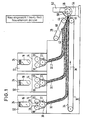
- each metering device 12 consists of a filling shaft 14 with a shop window 16 and two to three feed rollers 18, 20 arranged at the lower end of the shaft and an opening roller 22.
- the flakes present in the shaft, the upper limit of which is 24, are gripped by the feed rollers 18 and 20 rotating in the respective directions 26, 28 and fed to the opening roller 22 through the conveying gap formed between these two rollers.
- the latter rotates faster than the feed rollers and removes flakes from the supplied flake cotton wool and feeds them through a channel 30 in the form of open, loose flakes 32 onto the upper run 34 of the conveyor belt.
- the loose flake bundles 32.1 and 32.2 from the two further metering devices are placed in layers on the first layer formed by the flake bundle 32 and guided with the upper run of the conveyor belt 34 in the direction of arrow 36 to the right end of the mixing device in FIG.
- another rotating conveyor belt 38 which rotates in the direction of arrow 40 and whose lower run 42 to the upper run 34 of the conveyor belt 10 in Direction of conveyance 36 is inclined.
- the three layers 32, 32.1 and 32.2 are thus compressed and then captured in the feed nip of two feed rollers 44, 46.
- the feed rollers 44, 46 feed the layer structure formed in this way to an opening roller 48 which rotates in the direction of the arrow 50 and loosens the flakes from the layer structure and transfers them to the subsequent processing via a shaft 52. Any dirt or waste released by the opening by means of the opening roller 48 is collected in the outlet chamber 54 and, if necessary, removed from here by means of an air stream.
- FIG. 1 is not limited to three metering devices 12, but any number of layers can be arranged above the conveyor belt 10.
- the two side walls 56, 58 of the flake shaft extend close to the surfaces of the feed roller 18 and 20 and diverge slightly from one another so that no flake jams occur.
- the flakes 60 in the shaft 12 which have a high degree of opening, are gripped by the feed rollers 18 or 20 rotating in opposite directions in the direction of the arrow 26, 28 and compressed to form a flock cotton wool 62.
- the opening roller 22 then loosens the flakes out of this flake cotton wool and forms a flake flow 32 which continues in the direction of the arrow 64 in the direction of the conveyor belt.
- All flakes caught by the feed rollers rotating at the speed n are transported through a conveying gap, whose width x represents the smallest distance between the two feed rollers and whose length corresponds to the length of the feed rollers or the width of the side walls of the shaft.
- the axis of rotation of the feed roller 18 is identified by 66, the axis of rotation of the feed roller 20 by 68 and the axis of rotation of the opening roller 22 by 70.
- the axis of rotation 66 of the feed roller 18, like the axis of rotation 70 of the opening roller 22, is fixedly arranged in the flake shaft.
- the axis of rotation 68 of the feed roller 20 is, however, carried by two arms 72, only one of which can be seen in FIG. 2.
- the second arm 72 is located on the other end of the feed roller 20 and is designed in exactly the same way as the arm 72 shown.
- This arm 72 is mounted on the axis of rotation of the opening roller 22 and can therefore carry out rotary movements about this axis of rotation 70 in the direction of the double arrow 74. As can be seen, such movements lead to a change in the distance x.
- a prestressing device 76 is provided on the right-hand side of FIG. 2, in the form of a prestressing spring 78, which rests at one end against a stop 80 fixedly arranged on the filling shaft and at its other end against a stop 82 connected to the arm 72 .
- a rod 84 extends between the stop 76 and the stop 82 and is arranged displaceably within the stop 82.
- a second pretensioning device 76 is provided on the other end of the feed roller 20 and also presses on the associated arm 72 there.
- the two springs 78 therefore try to make the distance x smaller.
- the minimum distance x is predetermined by a stop device 86, which cooperates with the arm 72 shown.
- Another stop device 86 is located on the other end of the feed roller 20 and works in a corresponding manner with the arm 72 there.
- the distance x is set in operation depending on the pressure prevailing in the conveyor shaft, the density and the degree of opening of the flakes and the force of the spring 78, the size of the distance x being able to be determined by the displacement movement of the rod 84 within the stop 82.
- the rod 84 and the stop 82 are designed as a path measuring device.
- ⁇ material density
- n speed of the feed rollers
- u peripheral speed of the feed rollers
- d diameter of the feed rollers
- l length of the feed rollers
- x variable opening width of the conveyor gap
- s transport length.
- the mass flow equal to the current production ⁇ is v. ⁇ .
- ⁇ is the material density in the conveyor gap and this is at least essentially constant due to the prestressing with an essentially constant force.
- the opening cross-section is detected and integrated at a constant speed n 1 over the measurement over the fixed time interval t 2-t 1, resulting in the instantaneous production ⁇ 1.
- This value is compared to now m 'with the target production and control of the speed made so that a new speed gives n2 that remains constant for the next time interval.
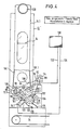
- FIG. 4 shows a metering device which corresponds approximately to the metering device 12 at the left end of FIG. 1.
- a further roller 88 is provided, which feeds the flakes in the shaft to the feed rollers 18 and 20.
- the roller 18 is designed to be displaceable, while the roller 20 remains stationary.
- the axis of rotation 66 of the displaceable feed roller 18.1 is here also supported by two arms 72.1, which in this example are not supported by the axis of rotation of the opening roller 22 but by the axis of rotation 90 of the additional roller 88.
- the pretensioning device 76.1 is now arranged on the left side of the flake shaft and, as in the embodiment according to FIG. 2, engages on the arm 72.1 at.
- neither the spring nor the displacement measuring device is shown here, but it goes without saying that these units are present in exactly the same way as in the embodiment according to FIG. 2. It is also understood that a further pretensioning device 76.1 is located on the other end of the roller 18 is provided.
- the feed rollers 18.1 and 20.1 and the further roller 88 are driven by a common motor 92.
- the drive consists of a chain 94 which is driven by a sprocket 96 on the output shaft of the motor 92.
- the chain 94 rotates with a tensioning device 104 on a sprocket 98 provided on the one end face of the roller 88 and on another sprocket 100 provided on the one end face of the roller 20.1 and on a sprocket 102 provided for tensioning the chain.
- the direction of rotation of the chain is indicated by arrow 106, from which the desired direction of rotation 28 of the feed roller 20.1 and the direction of rotation 108 of the further roller 88 result.
- the feed roller 18.1 is driven by a further rotating chain 110 which is driven by the chain wheel 98 designed as a double chain wheel.
- the sprockets 100 and 98 and the sprocket 112 on one end of the feed roller 18.1 have the same diameter, so that the speeds of rotation of these rollers are all the same.
- the opening roller 22.1 is driven by a separate motor 114 and a rotating chain 116.
- FIG. 4 also shows how the opening roller rotates within sheet metal guides 118 and 120, the sheet metal guide 120 being adjustable in the direction of the double arrow 122.
- the sheet 120 forms, together with another sheet 124, a guide channel 126 for the flake fleece 32.
- the special shape of this guide channel 126 slows down the flakes after they emerge from the area of the opening roller and guides them gently to the conveyor belt 34 without a pronounced air flow which could possibly interfere with the formation of sandwiches on the conveyor belt.
- the reference numeral 128 represents the feed channel by means of which the flakes are pneumatically transported into the shaft 14.
- 130 represents the computer, which controls the speed of the feed rollers via line 132 and receives the signal of the path measuring device installed in the pretensioning device 76.1 via line 134.
- FIG. 5 shows a further embodiment, the arrangement of the feed rollers 18, 20 and the opening roller 22 being designed in accordance with the arrangement according to FIG. 2, for which reason these parts are not described in detail.
- the motor 92.1 drives the feed roller 18 via the rotating chain 136.
- This chain is tensioned by the tensioning device 104.1 and the tensioning wheel 102.1.
- the second motor 114.1 drives an intermediate wheel 142 via the chain 140 which, via a further sprocket 144 coupled to it, a rotating chain 146, a further double sprocket 148 and a further rotating chain 150 which drives the opening roller 22 via the sprocket which is non-rotatably coupled to it .
- flakes are fed from a buffer space 154 to the further metering device 152, specifically from four feed rollers 156, 158, 160 and 162.
- These feed rollers 156, 158, 160, 162 are driven by their own motor 164, specifically via a rotating one Chain 166.
- the respective directions of rotation of the feed rollers 156, 158, 160, 162 can be seen from the arrows shown in each case. In order to secure these directions of rotation, it is necessary to drive the feed roller 160 through the feed roller 162 via a separate chain 168. From this it can be seen that the revolving chain 166 on the feed roller 166 is only guided via a freely rotatable sprocket.
- the metering device 152 is almost identical in construction to the metering device at the lower end of the filling shaft 14.2.
- the two feed rollers 170, 172 are driven by the motor 174, specifically via a revolving chain 176 which is essentially guided like the chain 136 at the lower end of the conveyor shaft, which is why the exact arrangement is not described in detail.
- the second feed roller 172 is driven by a separate rotating chain 78.
- the opening roller 180 is driven by the sprocket 142 via a further rotating chain 182, from which it can be seen that the sprocket 142 is designed as a double sprocket.
- the metering device 152 is switched on and off via light barriers 184, 186 which determine the upper and lower limits of the filling height. Since the shaft 14.2 is relatively wide, measured in the direction perpendicular to the plane of the drawing, two light barriers are provided on both sides in order to take into account the inclined positions of the upper limit of the flake filling. The metering device 152 can be switched on when both lower light barriers are free, and can be switched off when both upper light barriers 186 are interrupted.
- the lowest light barrier can represent an idle protection, the top one an overflow protection.
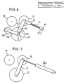
- FIG. 6 shows a schematic illustration of a pretensioning device 76.2 for the one feed roller 20, this pretensioning device being very similar to the pretensioning device 76 of FIG. 2.
- the ingenious geometry of the arrangement and the utilization of the feed roller 20 as a balance weight and by the provision of an additional balance weight 200 ensure that in all positions of the feed roller 20 within the intended swiveling range ⁇ there is at least essentially one constant clamping force is exerted on the flake mass 62 between the two feed rollers 18, 20.
- the spring 84 closes more is compressed than in the position shown, ie the clamping force exerted by the spring represents a maximum.
- the feed roller 20 causes a greater compression force on the spring 84 at the maximum angle ⁇ , since the feed roller 20 then has a larger lever arm for the weight force directed vertically downwards.
- the additional counterweight 200 which exerts a counterclockwise torque on the arm 72 via the arm 202, in turn generates an additional force in the direction of the spring force 84 on the fiber flakes, which are located between the two feed rollers 18 and 20.
- This additional force has a relatively small value in the angular position 206.
- the tension force exerted on the flakes located between the two feed rollers 18 and 20 is a value in position 206, which corresponds approximately to the difference between the maximum spring force and the maximum value of the weight force of the feed roller 20 directed against this spring force.
- the additional weight 200 exerts a maximum torque on the arm 72, which supports the force exerted by the spring 84.
- the force exerted on the flakes between the two feed rollers 18 and 20 essentially consists of the difference between the now reduced spring force 84 and the now reduced weight of the feed roller 20 plus the now increased weight of the additional weight 200, and one can use sophisticated Reaching the selection of the geometry as well as the individual weights and the spring force or the spring constant, that the forces exerted on the flakes between the two feed rollers 18 and 20 remain at least substantially constant over the entire angular range ⁇ .
- the equation for the system can easily be created if the torques exerted on the arm 72 about the axis of rotation 70 are calculated as a function of the angle ⁇ and then set to zero for each angle ⁇ . From these equations, optimal values for the individual weights as well as the spring force and for the spring constant can then be determined. It is also conceivable that at least a good approximation to a constant clamping force can be achieved even without the additional weight 200.
- the arm 72 must of course not be pivoted about the axis of rotation 70 of the opening roller 22. Instead, the articulation axis for the arm 72 can be chosen so that the clamping force remains constant as desired.
- FIG. 7 shows an alternative embodiment of the pretensioning device 76.3, which here has the form of a gas pressure spring.
- a gas pressure spring has the property of exerting a constant tensioning force over a relatively long stroke.
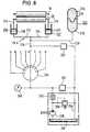
- Fig. 8 shows a hydraulic solution to the task of generating a constant clamping force.
- the feed rollers 18 and 20 are also shown schematically here.
- the preloading device 76.4 is here replaced by two piston-in-cylinder Arrangements 210 and 212 are formed which engage on opposite ends of the axis of the feed roller 20, for example the piston rods 214, 216 of the two piston-in-cylinder arrangements are articulated on the axis of rotation of the feed roller 20 and the cylinders 218, 220 of the two pistons are articulated in cylinder arrangements on the frame of the associated flake shaft.
- there is a pressure in the two cylinders which is predetermined by the accumulator 222.
- the accumulator 222 consists of a cylinder which is divided into two spaces 226 and 228 by means of a flexible membrane 224.
- the space 226 is filled with a gas, for example air, while the space 228 receives a hydraulic liquid which is connected via lines 230, 232 and 234 to the pressure spaces of the two cylinders 218, 220.
- a gas for example air
- the space 228 receives a hydraulic liquid which is connected via lines 230, 232 and 234 to the pressure spaces of the two cylinders 218, 220.
- an initial pressure is built up in the hydraulic system, specifically via a line 236, as will be explained in more detail below.
- a backflow via line 236 is not possible, however, as will also be explained in more detail later. Due to the set pressure, the piston-in-cylinder arrangements 210, 212 exert a predetermined force on the feed roller 20.
- liquid is displaced, for example, from the cylinders 218, 220 into the space 228 of the accumulator 222, which leads to an increase in the volume of this space and a compression of the gas volume 226.
- the pressure set in the system remains at least substantially constant, so that a constant tension force is exerted on the feed roller 20, which tension force is likewise at least substantially independent of the actual position of the feed roller .
- a hand pump 238 which sucks hydraulic fluid from a container 240 and is pressed into the pressure chambers 218, 220 and 228 via a check valve 242 and a distributor valve 226.
- the pressure established in these pressure rooms can be read off via the manometer 248.
- a relief valve 250 ensures that the pressure generated by the pump 238 does not exceed a maximum value, for example if the check valve 242 fails.
- Another relief valve 252 prevents excessive pressure from building up in the hydraulic pressure system. Should the valve 250 or the valve 252 bring about a pressure relief due to an overpressure, the relieved liquid flows back via line 254 into the container 240.
- the distributor valve 246 is constructed here in such a way that the pressures can be built up at eight different flake shafts A to H with associated metering devices. Two piston-in-cylinder arrangements 210 and 212 as well as an accumulator 222 and the associated lines are provided for each shaft. The individual pretensioning devices can be successively selected via the distribution valve 246. After the pressure setting in shaft H in the present example, the distributor valve is turned into a closed position in which the connection between the pump 238 and the individual pressure systems is interrupted. It is obvious that in this example a separate relief valve 252 must also be provided for each printing system.
- Relief valve 252 is configured to maintain a constant pressure. Either a separate system can be provided for each well, or all wells can be connected to a pump at the same time, in which case only a single relief valve 252, which now functions as a pressure regulator valve, is required for all wells. In the latter case, all shafts A to H are connected to the pump 238 via a multi-way distributor.
Landscapes
- Engineering & Computer Science (AREA)
- Textile Engineering (AREA)
- Preliminary Treatment Of Fibers (AREA)
Priority Applications (1)
| Application Number | Priority Date | Filing Date | Title |
|---|---|---|---|
| DE19904025476 DE4025476A1 (de) | 1990-02-12 | 1990-08-10 | Dosierverfahren und -vorrichtung zur abgabe vorgebbarer mengen von faserflocken pro zeiteinheit |
Applications Claiming Priority (4)
| Application Number | Priority Date | Filing Date | Title |
|---|---|---|---|
| DE3904390 | 1989-02-14 | ||
| DE3904390 | 1989-02-14 | ||
| DE3913997A DE3913997A1 (de) | 1989-02-14 | 1989-04-27 | Dosierverfahren und -vorrichtung zur abgabe vorgebbarer mengen von faserflocken |
| DE3913997 | 1989-04-27 |
Publications (4)
| Publication Number | Publication Date |
|---|---|
| EP0383246A2 true EP0383246A2 (fr) | 1990-08-22 |
| EP0383246A3 EP0383246A3 (en) | 1990-09-05 |
| EP0383246B1 EP0383246B1 (fr) | 1994-09-28 |
| EP0383246B2 EP0383246B2 (fr) | 2002-05-15 |
Family
ID=25877777
Family Applications (1)
| Application Number | Title | Priority Date | Filing Date |
|---|---|---|---|
| EP90102745A Expired - Lifetime EP0383246B2 (fr) | 1989-02-14 | 1990-02-12 | Procédé et appareil pour alimenter les flocons de fibres en quantité donnée |
Country Status (6)
| Country | Link |
|---|---|
| US (1) | US5121523A (fr) |
| EP (1) | EP0383246B2 (fr) |
| JP (1) | JP2776941B2 (fr) |
| CN (1) | CN1024821C (fr) |
| DE (2) | DE3913997A1 (fr) |
| RU (1) | RU2050424C1 (fr) |
Cited By (11)
| Publication number | Priority date | Publication date | Assignee | Title |
|---|---|---|---|---|
| EP0470577A1 (fr) * | 1990-08-10 | 1992-02-12 | Maschinenfabrik Rieter Ag | Procédé et dispositif de dosage pour la distribution de quantités prédétermineés de flocons de fibres par unité de temps |
| US5257438A (en) * | 1990-02-14 | 1993-11-02 | Maschinenfabrik Rieter Ag | Dosing method and apparatus for the delivery of predeterminate quantities of fiber flocks per unit of time |
| DE19630018A1 (de) * | 1996-07-25 | 1998-01-29 | Rieter Ag Maschf | Anlage zum Verarbeiten von Fasern |
| US6611994B2 (en) | 2000-06-23 | 2003-09-02 | Maschinenfabrik Rieter Ag | Method and apparatus for fiber length measurement |
| WO2007022658A1 (fr) * | 2005-08-25 | 2007-03-01 | Maschinenfabrik Rieter Ag | Systeme d'alimentation en flocons |
| EP2481551A1 (fr) * | 2011-01-26 | 2012-08-01 | Thüringisches Institut Für Textil- Und Kunststoff- Forschung E.V. | Procédé de dosage continu de fibres à empiler sur des machines à vis sans fin |
| WO2014008917A1 (fr) * | 2012-07-09 | 2014-01-16 | Thüringisches Institut für Textil- und Kunststoff-Forschung e.V. | Dispositif et procédé destinés au dosage continu de fibres discontinues sur des machines à vis sans fin |
| CN103741268A (zh) * | 2013-11-29 | 2014-04-23 | 吴江市大业丝绸整理有限公司 | 一种用于清理杂纤维的装置 |
| EP3699334A1 (fr) * | 2019-02-21 | 2020-08-26 | Oskar Dilo Maschinenfabrik KG | Dispositif d'alimentation d'une installation de formation du non-tissé |
| CN111945256A (zh) * | 2019-05-16 | 2020-11-17 | 奥斯卡迪罗机械制造公司 | 成绒机的进料装置 |
| CN112877787A (zh) * | 2020-07-20 | 2021-06-01 | 国际竹藤中心 | 一种网纹竹纤维制备机组 |
Families Citing this family (19)
| Publication number | Priority date | Publication date | Assignee | Title |
|---|---|---|---|---|
| DE4131759A1 (de) * | 1991-09-24 | 1993-03-25 | Hollingsworth Gmbh | Vorrichtung zum pneumatischen speisen von fasergut |
| DE19614519A1 (de) * | 1996-04-12 | 1997-10-16 | Bhs Corr Masch & Anlagenbau | Vorrichtung zum Fördern einer Materialbahn, insbesondere einer Wellpappenbahn |
| DE59711965D1 (de) | 1996-05-20 | 2004-11-04 | Rieter Ag Maschf | Anlage zum Verarbeiten von Fasern |
| JPH1088433A (ja) * | 1996-09-12 | 1998-04-07 | Taihei:Kk | 混紡方法及び装置並びにマット |
| EP0894878A3 (fr) | 1997-07-30 | 2000-04-19 | Maschinenfabrik Rieter Ag | Nettoyeur de flocons |
| DE69814034T2 (de) * | 1998-02-26 | 2004-03-11 | Philip Morris Products Inc. | Trichter |
| DE102005033180B4 (de) * | 2005-07-13 | 2020-03-12 | Trützschler GmbH & Co Kommanditgesellschaft | Vorrichtung zum Erfassen eines Parameters an mehreren, einem Streckwerk einer Spinnereimaschine zugeführten Faserbändern |
| DE102007014694B4 (de) * | 2007-03-27 | 2012-01-26 | Oskar Dilo Maschinenfabrik Kg | Vorrichtung zum geführten Transport einer Faserflockenmatte |
| US7811157B1 (en) * | 2009-07-23 | 2010-10-12 | Laitram, L.L.C. | Peeler with self-adjusting rollers |
| CN101724938B (zh) * | 2009-11-19 | 2011-09-28 | 太仓市万龙非织造工程有限公司 | 一种干法非织造前处理设备及设备上的罗拉组合输送装置 |
| CH706658A1 (de) * | 2012-06-29 | 2013-12-31 | Rieter Ag Maschf | Verfahren und Vorrichtung zur Regelung der Faserzufuhr zu einer Karde. |
| EP2695982A1 (fr) * | 2012-08-06 | 2014-02-12 | Oskar Dilo Maschinenfabrik KG | Dispositif et méthode pour égaliser ou obtenir un profil donné à un matelas de flocons de fibres |
| US20140041949A1 (en) * | 2012-08-09 | 2014-02-13 | Melvin D KERNUTT | Indirect Material Weighing Sensor |
| CN103103645B (zh) * | 2012-12-10 | 2015-06-24 | 苏州道众机械制造有限公司 | 一种纺织机械的微调罗拉 |
| CN103510201A (zh) * | 2013-09-12 | 2014-01-15 | 浙江新澳纺织股份有限公司 | 电子式改善条干均匀的方法 |
| JP6159632B2 (ja) * | 2013-09-26 | 2017-07-05 | ユニ・チャーム株式会社 | 吸収体の製造方法及び製造装置 |
| CN103710794B (zh) * | 2014-01-02 | 2016-03-30 | 孙海侠 | 一种开花机的喂给罗拉 |
| CN110592739B (zh) * | 2019-10-18 | 2024-09-20 | 盐城金大纺织机械制造有限公司 | 一种多品种棉层叠夹式混纺系统 |
| CN115872122B (zh) * | 2023-02-09 | 2023-05-23 | 山东日发纺织机械有限公司 | 一种传送速度的控制方法、控制器及生产线 |
Family Cites Families (24)
| Publication number | Priority date | Publication date | Assignee | Title |
|---|---|---|---|---|
| DE196821C (fr) * | ||||
| GB735172A (en) * | 1952-05-16 | 1955-08-17 | Tmm Research Ltd | Improvements relating to the preparation of blended fibrous materials |
| FR1270586A (fr) * | 1960-07-18 | 1961-09-01 | Perfectionnements aux procédés et aux machines pour le mélange des matières textiles en vue de leur filature | |
| US3448905A (en) * | 1967-02-07 | 1969-06-10 | Topps Chewing Gum Inc | Article feed control |
| GB1270670A (en) * | 1968-10-30 | 1972-04-12 | British Iron Steel Research | Rolling sheet or strip from particulate material |
| DE1946213B2 (de) * | 1969-09-12 | 1971-09-02 | Heinrich Weiste & Co Gmbh, 4770 Soest | Dosiergeraet fuer pneumatisch arbeitnde verteilersysteme |
| CH562889A5 (fr) * | 1972-12-05 | 1975-06-13 | Rieter Ag Maschf | |
| US3889319A (en) * | 1973-10-23 | 1975-06-17 | Crompton & Knowles Corp | Method and system for producing blended textile fibrous materials |
| DE2834586C2 (de) * | 1978-08-07 | 1983-02-03 | Trützschler GmbH & Co KG, 4050 Mönchengladbach | Verfahren und Vorrichtung zur Regelung der einer Karde zuzuführenden Flockenmenge |
| JPS5637325A (en) * | 1979-09-03 | 1981-04-11 | Mitsubishi Rayon Co | Production of special crimped yarn |
| JPS594319B2 (ja) * | 1979-09-14 | 1984-01-28 | 孝生 岩崎 | 筆記具 |
| US4476611A (en) * | 1980-11-17 | 1984-10-16 | Automatic Material Handling, Inc. | Fiber feeding apparatus with fiber leveling means |
| DE3110668A1 (de) * | 1981-03-19 | 1982-09-30 | Maschinen- und Apparatevertrieb Helmut Strunk, 5241 Kirchen-Freusburg | Messanordnung fuer die vorschubgeschwindigkeit, die vorgeschobene laenge, das gewicht einer vorgeschobenen laenge eines angetriebenen gestreckten koerpers sowie zur regelung seiner vorschubgeschwindigkeit |
| DE3151063C2 (de) * | 1981-12-23 | 1984-05-24 | Trützschler GmbH & Co KG, 4050 Mönchengladbach | Verfahren und Vorrichtung zum Mischen von Textilfasern |
| GB2138578B (en) * | 1983-04-19 | 1986-08-28 | Haigh Chadwick Ltd | Fibre metering arrangement |
| DE3535684C2 (de) * | 1985-10-05 | 1996-06-05 | Truetzschler Gmbh & Co Kg | Vorrichtung zur Speisung eines Öffners oder Reinigers für Textilfaserflocken |
| JPH0246693B2 (ja) * | 1986-05-12 | 1990-10-17 | Ohara Tekkosho Kk | Senitafutonojunkankaisensochi |
| US4682388A (en) * | 1986-08-22 | 1987-07-28 | John D. Hollingsworth On Wheels, Inc. | Textile flock feed control system and method |
| DE3636381A1 (de) * | 1986-10-25 | 1988-05-11 | Simar Foerdertechnik Gmbh | Vorrichtung mit einem sammelbehaelter und einer austrageinrichtung |
| IN170276B (fr) * | 1986-12-12 | 1992-03-07 | Rieter Ag Maschf | |
| DE3705148C3 (de) * | 1987-02-18 | 1996-11-21 | Spinnbau Gmbh | Vorrichtung zum Zuführen von Fasermaterial in Wattevliesform zu einer Krempel, Karde oder dergleichen |
| IN171263B (fr) * | 1987-04-13 | 1992-08-29 | Rieter Ag Maschf | |
| DE3713590A1 (de) * | 1987-04-23 | 1987-10-08 | Hergeth Hubert | Schachtmischer |
| DE3733632C2 (de) * | 1987-10-05 | 1998-04-23 | Truetzschler Gmbh & Co Kg | Vorrichtung bei einer Karde oder Krempel zur Vergleichmäßigung des Faserbandes oder -vlieses |
-
1989
- 1989-04-27 DE DE3913997A patent/DE3913997A1/de not_active Ceased
-
1990
- 1990-02-12 EP EP90102745A patent/EP0383246B2/fr not_active Expired - Lifetime
- 1990-02-12 DE DE59007294T patent/DE59007294D1/de not_active Expired - Fee Related
- 1990-02-13 RU SU904743227A patent/RU2050424C1/ru active
- 1990-02-13 CN CN90101432A patent/CN1024821C/zh not_active Expired - Fee Related
- 1990-02-14 US US07/480,123 patent/US5121523A/en not_active Expired - Lifetime
- 1990-02-14 JP JP2031658A patent/JP2776941B2/ja not_active Expired - Lifetime
Cited By (13)
| Publication number | Priority date | Publication date | Assignee | Title |
|---|---|---|---|---|
| US5257438A (en) * | 1990-02-14 | 1993-11-02 | Maschinenfabrik Rieter Ag | Dosing method and apparatus for the delivery of predeterminate quantities of fiber flocks per unit of time |
| EP0470577A1 (fr) * | 1990-08-10 | 1992-02-12 | Maschinenfabrik Rieter Ag | Procédé et dispositif de dosage pour la distribution de quantités prédétermineés de flocons de fibres par unité de temps |
| DE19630018A1 (de) * | 1996-07-25 | 1998-01-29 | Rieter Ag Maschf | Anlage zum Verarbeiten von Fasern |
| US6611994B2 (en) | 2000-06-23 | 2003-09-02 | Maschinenfabrik Rieter Ag | Method and apparatus for fiber length measurement |
| WO2007022658A1 (fr) * | 2005-08-25 | 2007-03-01 | Maschinenfabrik Rieter Ag | Systeme d'alimentation en flocons |
| DE102005040399A1 (de) * | 2005-08-25 | 2007-03-01 | Maschinenfabrik Rieter Ag | Flockenbeschickungssystem |
| EP2481551A1 (fr) * | 2011-01-26 | 2012-08-01 | Thüringisches Institut Für Textil- Und Kunststoff- Forschung E.V. | Procédé de dosage continu de fibres à empiler sur des machines à vis sans fin |
| WO2014008917A1 (fr) * | 2012-07-09 | 2014-01-16 | Thüringisches Institut für Textil- und Kunststoff-Forschung e.V. | Dispositif et procédé destinés au dosage continu de fibres discontinues sur des machines à vis sans fin |
| CN103741268A (zh) * | 2013-11-29 | 2014-04-23 | 吴江市大业丝绸整理有限公司 | 一种用于清理杂纤维的装置 |
| EP3699334A1 (fr) * | 2019-02-21 | 2020-08-26 | Oskar Dilo Maschinenfabrik KG | Dispositif d'alimentation d'une installation de formation du non-tissé |
| US11649568B2 (en) | 2019-02-21 | 2023-05-16 | Oskar Dilo Maschinenfabrik Kg | Feed device of a machine for forming a nonwoven web |
| CN111945256A (zh) * | 2019-05-16 | 2020-11-17 | 奥斯卡迪罗机械制造公司 | 成绒机的进料装置 |
| CN112877787A (zh) * | 2020-07-20 | 2021-06-01 | 国际竹藤中心 | 一种网纹竹纤维制备机组 |
Also Published As
| Publication number | Publication date |
|---|---|
| US5121523A (en) | 1992-06-16 |
| EP0383246B2 (fr) | 2002-05-15 |
| EP0383246B1 (fr) | 1994-09-28 |
| CN1024821C (zh) | 1994-06-01 |
| CN1045609A (zh) | 1990-09-26 |
| RU2050424C1 (ru) | 1995-12-20 |
| DE59007294D1 (de) | 1994-11-03 |
| EP0383246A3 (en) | 1990-09-05 |
| DE3913997A1 (de) | 1990-08-23 |
| JP2776941B2 (ja) | 1998-07-16 |
| JPH03820A (ja) | 1991-01-07 |
Similar Documents
| Publication | Publication Date | Title |
|---|---|---|
| EP0383246B1 (fr) | Procédé et appareil pour alimenter les flocons de fibres en quantité donnée | |
| DE69020530T2 (de) | Verfahren und Vorrichtung zum Ausstrecken von Teig. | |
| DE2506061B2 (de) | Wiegeeinrichtung zum kontinuierlichen Wiegen einer durchlaufenden Faserschicht | |
| DE19855571A1 (de) | Vorrichtung an einer Spinnereimaschine zum Herstellen eines Faserverbandes, z.B. aus Baumwolle, Chemiefasern | |
| DE3545673C2 (de) | Portioniermaschine | |
| DE1535616A1 (de) | Webmaschine | |
| EP0470577B1 (fr) | Procédé et dispositif de dosage pour la distribution de quantités prédétermineés de flocons de fibres par unité de temps | |
| DE69912537T2 (de) | Vorrichtung und Verfahren zum Ausgleichen der Zufuhr von Textilfasern in Form einer Matte zu einer Karde | |
| AT395726B (de) | Vorrichtung zur vergleichmaessigung des faserbandes oder -vlieses bei einer karde, krempel od.dgl. | |
| CH681156A5 (fr) | ||
| DE2220748C3 (de) | Verfahren und Vorrichtung zur Vergleichmäßigung des Querschnitts oder des Gewichtes pro Längeneinheit eines mittels Karde oder Krempel produzierten Faserbandes | |
| DE4025476A1 (de) | Dosierverfahren und -vorrichtung zur abgabe vorgebbarer mengen von faserflocken pro zeiteinheit | |
| CH693676A5 (de) | Vorrichtung zum Messen der Dicke und/oder der Ungleichmässigkeit von Faserbändern. | |
| DE2915710A1 (de) | Wiegevorrichtung | |
| DE3544285A1 (de) | Vorrichtung zur wechselweisen einstellung der messerschneide in einer schneidemaschine | |
| DE2302472A1 (de) | Verfahren und vorrichtung zum ueberwachen und regeln der bandspannung | |
| DE2138855B2 (de) | Verdichtungstrichter zum Messen der Stärke eines aus einem Streckwerk auslaufenden Faserbandes | |
| DD292035A5 (de) | Dosierverfahren und -vorrichtung zur abgabe vorgebbarer mengen von faserflocken | |
| EP0064584B1 (fr) | Procédé et dispositif pour déposer un ruban de fibres textiles | |
| DE19827712A1 (de) | Vorrichtung zum direkten oder indirekten Auftragen eines flüssigen oder pastösen Auftragsmediums auf eine laufende Materialbahn | |
| EP0265783A2 (fr) | Dispositif d'alimentation pour broyeurs à cylindres, en particulier pour graines oléagineuses | |
| DE3615357A1 (de) | Verfahren und vorrichtung zur bildung einer bahn | |
| DE3834039A1 (de) | Querbandanordnung am ausgang einer karde | |
| DE2509720A1 (de) | Verteiler einer zigarettenstrangmaschine | |
| DE2015790C3 (de) | Verfahren und Vorrichtung zum Portionieren von Schnittabak oder ähnlichem faserigen Material |
Legal Events
| Date | Code | Title | Description |
|---|---|---|---|
| PUAI | Public reference made under article 153(3) epc to a published international application that has entered the european phase |
Free format text: ORIGINAL CODE: 0009012 |
|
| PUAL | Search report despatched |
Free format text: ORIGINAL CODE: 0009013 |
|
| AK | Designated contracting states |
Kind code of ref document: A2 Designated state(s): CH DE FR GB IT LI |
|
| AK | Designated contracting states |
Kind code of ref document: A3 Designated state(s): CH DE FR GB IT LI |
|
| 17P | Request for examination filed |
Effective date: 19910305 |
|
| 17Q | First examination report despatched |
Effective date: 19920929 |
|
| GRAA | (expected) grant |
Free format text: ORIGINAL CODE: 0009210 |
|
| AK | Designated contracting states |
Kind code of ref document: B1 Designated state(s): CH DE FR GB IT LI |
|
| PG25 | Lapsed in a contracting state [announced via postgrant information from national office to epo] |
Ref country code: GB Free format text: LAPSE BECAUSE OF FAILURE TO SUBMIT A TRANSLATION OF THE DESCRIPTION OR TO PAY THE FEE WITHIN THE PRESCRIBED TIME-LIMIT Effective date: 19940928 |
|
| REF | Corresponds to: |
Ref document number: 59007294 Country of ref document: DE Date of ref document: 19941103 |
|
| ITF | It: translation for a ep patent filed | ||
| GBT | Gb: translation of ep patent filed (gb section 77(6)(a)/1977) |
Effective date: 19950106 |
|
| ET | Fr: translation filed | ||
| PLBI | Opposition filed |
Free format text: ORIGINAL CODE: 0009260 |
|
| 26 | Opposition filed |
Opponent name: TRUETZSCHLER GMBH & CO. KG Effective date: 19950607 |
|
| PG25 | Lapsed in a contracting state [announced via postgrant information from national office to epo] |
Ref country code: FR Effective date: 19951031 |
|
| REG | Reference to a national code |
Ref country code: FR Ref legal event code: ST |
|
| PLBF | Reply of patent proprietor to notice(s) of opposition |
Free format text: ORIGINAL CODE: EPIDOS OBSO |
|
| PLBF | Reply of patent proprietor to notice(s) of opposition |
Free format text: ORIGINAL CODE: EPIDOS OBSO |
|
| PLBF | Reply of patent proprietor to notice(s) of opposition |
Free format text: ORIGINAL CODE: EPIDOS OBSO |
|
| PLBF | Reply of patent proprietor to notice(s) of opposition |
Free format text: ORIGINAL CODE: EPIDOS OBSO |
|
| RDAH | Patent revoked |
Free format text: ORIGINAL CODE: EPIDOS REVO |
|
| APAC | Appeal dossier modified |
Free format text: ORIGINAL CODE: EPIDOS NOAPO |
|
| APAE | Appeal reference modified |
Free format text: ORIGINAL CODE: EPIDOS REFNO |
|
| APAC | Appeal dossier modified |
Free format text: ORIGINAL CODE: EPIDOS NOAPO |
|
| PGFP | Annual fee paid to national office [announced via postgrant information from national office to epo] |
Ref country code: CH Payment date: 19990128 Year of fee payment: 10 |
|
| APAE | Appeal reference modified |
Free format text: ORIGINAL CODE: EPIDOS REFNO |
|
| PG25 | Lapsed in a contracting state [announced via postgrant information from national office to epo] |
Ref country code: LI Free format text: LAPSE BECAUSE OF NON-PAYMENT OF DUE FEES Effective date: 20000229 Ref country code: CH Free format text: LAPSE BECAUSE OF NON-PAYMENT OF DUE FEES Effective date: 20000229 |
|
| REG | Reference to a national code |
Ref country code: CH Ref legal event code: PL |
|
| APAC | Appeal dossier modified |
Free format text: ORIGINAL CODE: EPIDOS NOAPO |
|
| PLAW | Interlocutory decision in opposition |
Free format text: ORIGINAL CODE: EPIDOS IDOP |
|
| REG | Reference to a national code |
Ref country code: GB Ref legal event code: IF02 |
|
| PGFP | Annual fee paid to national office [announced via postgrant information from national office to epo] |
Ref country code: GB Payment date: 20020124 Year of fee payment: 13 |
|
| PUAH | Patent maintained in amended form |
Free format text: ORIGINAL CODE: 0009272 |
|
| STAA | Information on the status of an ep patent application or granted ep patent |
Free format text: STATUS: PATENT MAINTAINED AS AMENDED |
|
| 27A | Patent maintained in amended form |
Effective date: 20020515 |
|
| AK | Designated contracting states |
Kind code of ref document: B2 Designated state(s): CH DE FR GB IT LI |
|
| GBV | Gb: ep patent (uk) treated as always having been void in accordance with gb section 77(7)/1977 [no translation filed] |
Effective date: 19940928 |
|
| EN | Fr: translation not filed | ||
| APAH | Appeal reference modified |
Free format text: ORIGINAL CODE: EPIDOSCREFNO |
|
| PGFP | Annual fee paid to national office [announced via postgrant information from national office to epo] |
Ref country code: DE Payment date: 20070216 Year of fee payment: 18 |
|
| PGFP | Annual fee paid to national office [announced via postgrant information from national office to epo] |
Ref country code: IT Payment date: 20070613 Year of fee payment: 18 |
|
| PG25 | Lapsed in a contracting state [announced via postgrant information from national office to epo] |
Ref country code: DE Free format text: LAPSE BECAUSE OF NON-PAYMENT OF DUE FEES Effective date: 20080902 |
|
| PG25 | Lapsed in a contracting state [announced via postgrant information from national office to epo] |
Ref country code: IT Free format text: LAPSE BECAUSE OF NON-PAYMENT OF DUE FEES Effective date: 20080212 |