EP0383402B1 - Dispositif pour maintenir une salle hors poussière et salle blanche munie d'un tel dispositif - Google Patents
Dispositif pour maintenir une salle hors poussière et salle blanche munie d'un tel dispositif Download PDFInfo
- Publication number
- EP0383402B1 EP0383402B1 EP90200332A EP90200332A EP0383402B1 EP 0383402 B1 EP0383402 B1 EP 0383402B1 EP 90200332 A EP90200332 A EP 90200332A EP 90200332 A EP90200332 A EP 90200332A EP 0383402 B1 EP0383402 B1 EP 0383402B1
- Authority
- EP
- European Patent Office
- Prior art keywords
- air
- space
- inlet
- filter
- wall
- Prior art date
- Legal status (The legal status is an assumption and is not a legal conclusion. Google has not performed a legal analysis and makes no representation as to the accuracy of the status listed.)
- Expired - Lifetime
Links
Images
Classifications
-
- B—PERFORMING OPERATIONS; TRANSPORTING
- B01—PHYSICAL OR CHEMICAL PROCESSES OR APPARATUS IN GENERAL
- B01D—SEPARATION
- B01D46/00—Filters or filtering processes specially modified for separating dispersed particles from gases or vapours
-
- B—PERFORMING OPERATIONS; TRANSPORTING
- B01—PHYSICAL OR CHEMICAL PROCESSES OR APPARATUS IN GENERAL
- B01D—SEPARATION
- B01D46/00—Filters or filtering processes specially modified for separating dispersed particles from gases or vapours
- B01D46/10—Particle separators, e.g. dust precipitators, using filter plates, sheets or pads having plane surfaces
- B01D46/12—Particle separators, e.g. dust precipitators, using filter plates, sheets or pads having plane surfaces in multiple arrangements
-
- F—MECHANICAL ENGINEERING; LIGHTING; HEATING; WEAPONS; BLASTING
- F24—HEATING; RANGES; VENTILATING
- F24F—AIR-CONDITIONING; AIR-HUMIDIFICATION; VENTILATION; USE OF AIR CURRENTS FOR SCREENING
- F24F3/00—Air-conditioning systems in which conditioned primary air is supplied from one or more central stations to distributing units in the rooms or spaces where it may receive secondary treatment; Apparatus specially designed for such systems
- F24F3/12—Air-conditioning systems in which conditioned primary air is supplied from one or more central stations to distributing units in the rooms or spaces where it may receive secondary treatment; Apparatus specially designed for such systems characterised by the treatment of the air otherwise than by heating and cooling
- F24F3/16—Air-conditioning systems in which conditioned primary air is supplied from one or more central stations to distributing units in the rooms or spaces where it may receive secondary treatment; Apparatus specially designed for such systems characterised by the treatment of the air otherwise than by heating and cooling by purification, e.g. by filtering; by sterilisation; by ozonisation
- F24F3/163—Clean air work stations, i.e. selected areas within a space which filtered air is passed
Definitions
- the invention relates to a device for maintaining a space dust poor having an open side and at the side opposite to said open side a wall filter and a channel space located at the side of the wall filter turned away from the space, the channel space being connected to an air inlet via compressor means.
- Such devices are known in several forms wherewith it is important that in the space a stream pattern is maintained with which no unfiltered air can attain the inside of the space.
- EP-A-0.062.719 a device of the indicated type is shown in which as an additional means to prevent entrance into the space of unfiltered air the air velocity towards the open side is varied along one direction of the said open side in order to adapt the stream pattern to any obstacles in the space.
- the particles may be bacteria or bacteria colonies or dust particles of medicines which may be dangerous to people working with them.
- Patent Abstract of Japan (vol. 11 no. 330,(M636) [2777], 28th October 1987, page 105 M 636; & JP-A-62 112 941 describe a device for maintaining a space dust poor having an open side and at the side opposite said open side an air pervious wall, a channel space being located at the side of the wall turned away from the space, said channel space being connected to a filter and via compressor means to an air inlet, compressor means connecting an air inlet to a further channel space connected to a filter having a vertical air exit giving a downwardly directed air flow adjacent the side of said space which is opposite to said air pervious wall, said air inlet being located below the lower side of said space.
- the invention aims to improve such a device in order to obtain a dust poor space which is accessible from the side opposite said channel space.
- the invention provides a specially effective device with a dust'poor space having an opening.
- the invention consists in that a further filter with at the open side a downwardly directed output surface and at its side turned away from said surface adjoins a further channel space which via compressor means is connected to a further inlet, the wall filter and the further filter having such stream resistances and the compressor means being adapted to generate such pressures in the channel space and the further channel space, that the air exit velocity from the further filter is higher than that from the wall filter, the inlet and the further inlet for the compressor means being located at the under side of the open side.
- Patent Abstracts of Japan, vol. 10, no. 238 (M-508) [2294] of August 16, 1986 shows a clean bench device having a feed of filtered air through the ceiling and the lower part of the back wall. Here no shielding occurs to prevent air from the room to enter the upper part of the space, for instance if swirls would occur.
- the air volume leaving the further filter has a greater velocity than has the volume coming from the back wall filter and flowing transversely to it. This means that at the location where they meet some turbulences will occur. These turbulences will, however, not pass through the air shield issuing from the further filter. Further it is important that the air for both filters is sucked in below the opening, by reason of which the air shield together with air from the wall filter added to it, at least an important part thereof, is sucked away at the lower side which keeps the air curtain also closed at the lower side.
- the air can be replaced by air from outside the space, at least partially, which gives an important heat dissipation possibility, for instance when cooling down electronic chips of semi-conducter material coming from a diffusion furnace. Further the small turbulences occurring at the surface where both air currents meet have a cleaning action for such like chips.
- the inlet and the further inlet are located beside each other and that the compressor means are formed by a first compressor unit connected to the channel space and a second compressor unit connected to the further channel space.
- the compressor means are formed by a first compressor unit connected to the channel space and a second compressor unit connected to the further channel space.
- the inlet is divided into two parts besides the further inlet, located between them and that the first compressor unit consists of two compressors which each compresses the air originating from the inlet or the further inlet respectively.
- the first compressor unit consists of two compressors which each compresses the air originating from the inlet or the further inlet respectively.
- the air sucked in through the inlet or inlets is prefiltered.
- an inventive device often is placed in a so-called clean room and for that reason only little particles will be present which will be catched by a pre-filter (a normal prefilter catches for instance 98% of the particles larger than 5 ⁇ m) it has nevertheless appeared that herewith the time of use of the filters can be prolonged.
- An inventive device is preferably placed in a so-called clean room, that is to say a space with a current which is only very little turbulent and on base of American terminology often is called a laminair current, which is not quite correct.
- a laminair current which is not quite correct.
- two systems namely the cross system, in which air is fed in through a vertical wall and then moves horizontally through the room, and the pattern with down flow, in which air is regularly fed in from the ceiling and is exhausted through the floor or near to the floor.
- another embodiment of the invention provides a dust poor room with air down flow, in which a space is to be kept specially dust poor with an own air filtering and circulation system having an opening at one side, which is characterized in that the air filtering and circulation system is adapted to suck in air below said opening to compress it, filter it and feed it with a first pressure to wall filters in a wall opposing said opening and with such a pressure to a further filter located above the opening and having a downwardly directed exit surface, that the stream exit velocity from the further filter is higher than that from the wall filter.
- a special application hereof is formed by the mechanism for feeding semi-conductor chips into a furnace in which they have to be heated, for instance to be submitted to a diffusion treatment. When such chips leave the furnace they have a very high temperature which may give rise to a considerable convection current.
- the invention is specially effective, because at the one hand it is prevented that the convection current can lead to it that non-filtered air is sucked in from the space in which the device is located and at the other hand that by reason of the circulation of air which is refreshed to a considerable degree a good heat removal is obtained. Therewith it has appeared that the turbulence which can occur at the border of both air currents may be favourable for removing dust particles from semi conductor chips cooling down.
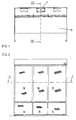
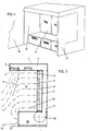
- an inventive device has been shown with three inlets with prefilters 1a, 1b and 1c, which at the back side have a chamber 2 of which 2b is visible in fig. 3 with each a fan or compressor 3, of which 3b is visible in fig. 3, the exit of the fans behind 1a and 1c being connected to a channel space 4, which is limited by filters with a high filtering activity, such as a so-called HEPA (High Efficiency Particle Air)-filter, which retains 99,997% of the particles having a diameter of 0,3 ⁇ m or more.
- HEPA High Efficiency Particle Air
- prefilter 1b The space behind prefilter 1b is connected to a channel 5 which runs upwardly along the back wall of the device and debouches in a channel 6 running along the ceiling 7 in which at the front side a HEPA filter 8 is mounted, the exit plane of which is directed downwardly.
- the space 4 is delimited by three vertically mounted HEPA filters 10, connected in parallel and fed by fans positioned behind the pre-filters 1a and 1c.
- the rotational speed of these fans is adjusted in such a way that the air current leaving the filters 10 has a velocity of about 0,45 m/sec.
- the fan 3b located behind pre-filter 2b rotates with such a speed that the air current leaving the filter 8 in vertically downward direction has a velocity of about 0,55 m/sec.
- Furter 12 indicates a current followed by air leaving the lower parts of filters 10.
- the air is located in a practically turbulence free, may it be curved stream pattern and attains the upper side of the filters 1a, 1b and 1c. Also higher up current trajectories, such as 13 and 14 have practically no turbulence in the space 15 in which the concentration of particles is kept as low as possible.
- part of the air current from filter 8 and also part of the air current from filter 10 is removed and via trajectories 16 fresh air is fed to the pre-filters 1a, 1b and 1c.
- the particle concentration in space 15 may be 1 or 2 magnitudes (that is 10 ⁇ 1 of 10 ⁇ 2 times) lower than in the room in which the device is located.
- the invention contains a feed and discharge device, which by the way is known per se, for a diffusion furnace for semi-conductor chips, which have to be exposed to a heat treatment up till for instance 900° C during a considerable time.
- the one side wall prolongation 17 preferably is part of a schematically indicated wall 18, which delimits the down flow clean room in which the device is located with a diffusion furnace known per se behind this wall 18.
- Through closable holes in the side wall 19 then supports with semiconductor chips known per se can be shoved into the furnace, been heat treated there and again shoved out of the furnace. This technic is known per se and will not further be discussed here.
- the invention appears very effective in impeding entrance of air which has not passed one of the filters 8 or 10.
- a further advantage of the invention is, that in a down flow clean roon a vertical air current with a velocity of about 0,45 m/sec. prevails, which is a relatively small difference of air velocity with the velocity of the air leaving filter 8, which may be for instance 0,55 m/sec.
- the current velocity of the air leaving horizontally filters 10 is for instance 0,45 m/sec.
Landscapes
- Chemical & Material Sciences (AREA)
- Chemical Kinetics & Catalysis (AREA)
- Engineering & Computer Science (AREA)
- Combustion & Propulsion (AREA)
- Mechanical Engineering (AREA)
- General Engineering & Computer Science (AREA)
- Ventilation (AREA)
- Filtering Of Dispersed Particles In Gases (AREA)
- Jib Cranes (AREA)
Claims (8)
- Dispositif pour maintenir un espace (15) dépoussiéré ayant une face ouverte et sur la face opposée à ladite face ouverte une paroi perméable à l'air (10), un espace de canal (4) étant disposé sur la face de la paroi orientée dans la direction opposée à l'espace (15), ledit espace de canal (4) étant relié à un filtre, et par l'intermédiaire d'un moyen compresseur (3a, 3c) à une arrivée d'air (1a, 1c), un moyen compresseur (3b) reliant une arrivée d'air (1b) à un autre espace de canal (5, 6) relié à un fil (8) ayant une sortie d'air verticale (9) qui établit un flux d'air dirigé vers le bas, adjacent à la face dudit espace qui est opposée à ladite paroi perméable à l'air (10), ladite arrivée d'air (1a, 1b, 1c) étant située sous la face inférieure dudit espace (15), caractérisé en ce que ladite paroi perméable (10) est la surface de sortie d'un filtre de paroi (10) et en ce que le filtre (8, 10) comporte des résistances s'opposant à la circulation et en ce que les moyens compresseurs (3a, b, c) sont conçus pour créer des pressions telles que la vitesse de sortie de l'air du second filtre (8) est supérieure à la vitesse de sortie du filtre de paroi (10).
- Dispositif selon la revendication 1, caractérisé en ce que l'arrivé (1a, 1c) et l'autre arrivée (1b) sont disposées côte à côte et en ce que les moyens compresseurs sont formés par une première unité de compresseur (2a, 2c) relié à l'espace de canal (4), et par une seconde unité de compresseur (2b) reliée à l'autre espace de canal (5, 6).
- Dispositif selon la revendication 1, caractérisé en ce que l'arrivée est divisée en deux parties (1a, 1b) placées de chaque côté de l'autre arrivée (1b) et en ce que la première unité de compresseur comprend deux compresseurs qui compriment chacun l'air provenant de la première arrivée ou de l'autre arrivée respectivement.
- Dispositif selon l'une quelconque des revendications précédentes, caractérisé en ce que l'arrivée ou les arrivées s'étendent sur la longueur de la face inférieure de la face ouverte.
- Dispositif selon l'une quelconque des revendications précédentes, caractérisé en ce que l'air aspiré à travers l'arrivée ou les arrivées est pré-filtré.
- Dispositif selon l'une quelconque des revendications précédentes, caractérisé en ce que les délimitations de la paroi latérale s'étendent jusqu'au bord avant de l'autre filtre (8).
- Compartiment dépoussiéré avec circulation d'air vers le bas, dans lequel un dispositif selon l'une quelconque des revendications précédentes est installé pour maintenir un espace (15) particulièrement dépoussiéré.
- Local dépoussiéré selon la revendication 7 pour remplir un dispositif de chargement destiné à un four de diffusion pour le traitement des puces de semi-conducteur, une paroi latérale du espace comportant des ouvertures qui se ferment et qui permettent de laisser passer des conteneurs de puces arrivant au four, caractérisé en ce que le four est située à l'extérieur du local et en ce que ladite paroi latérale dudit espace fait partie de la cloison dudit local.
Priority Applications (1)
| Application Number | Priority Date | Filing Date | Title |
|---|---|---|---|
| AT90200332T ATE83850T1 (de) | 1989-02-17 | 1990-02-14 | Einrichtung zum staubarmhalten von raeumen und reinraum, versehen mit dieser einrichtung. |
Applications Claiming Priority (2)
| Application Number | Priority Date | Filing Date | Title |
|---|---|---|---|
| NL8900390 | 1989-02-17 | ||
| NL8900390A NL8900390A (nl) | 1989-02-17 | 1989-02-17 | Inrichting voor het stofarm houden van een ruimte en clean room voorzien van een dergelijke ruimte. |
Publications (2)
| Publication Number | Publication Date |
|---|---|
| EP0383402A1 EP0383402A1 (fr) | 1990-08-22 |
| EP0383402B1 true EP0383402B1 (fr) | 1992-12-23 |
Family
ID=19854150
Family Applications (1)
| Application Number | Title | Priority Date | Filing Date |
|---|---|---|---|
| EP90200332A Expired - Lifetime EP0383402B1 (fr) | 1989-02-17 | 1990-02-14 | Dispositif pour maintenir une salle hors poussière et salle blanche munie d'un tel dispositif |
Country Status (4)
| Country | Link |
|---|---|
| EP (1) | EP0383402B1 (fr) |
| AT (1) | ATE83850T1 (fr) |
| DE (1) | DE69000619D1 (fr) |
| NL (1) | NL8900390A (fr) |
Families Citing this family (2)
| Publication number | Priority date | Publication date | Assignee | Title |
|---|---|---|---|---|
| US6869458B2 (en) * | 2003-05-05 | 2005-03-22 | Sanki Engineering Co., Ltd. | Bioclean room unit |
| DE102017124384A1 (de) * | 2017-10-19 | 2019-04-25 | Khs Gmbh | Einhausung für eine industrielle Anlage |
Family Cites Families (1)
| Publication number | Priority date | Publication date | Assignee | Title |
|---|---|---|---|---|
| US4412849A (en) * | 1981-04-09 | 1983-11-01 | Klenzaids Engineers Private Limited | Method and apparatus for control of gas-borne particulates |
-
1989
- 1989-02-17 NL NL8900390A patent/NL8900390A/nl not_active Application Discontinuation
-
1990
- 1990-02-14 AT AT90200332T patent/ATE83850T1/de not_active IP Right Cessation
- 1990-02-14 EP EP90200332A patent/EP0383402B1/fr not_active Expired - Lifetime
- 1990-02-14 DE DE9090200332T patent/DE69000619D1/de not_active Expired - Lifetime
Also Published As
| Publication number | Publication date |
|---|---|
| DE69000619D1 (de) | 1993-02-04 |
| EP0383402A1 (fr) | 1990-08-22 |
| NL8900390A (nl) | 1990-09-17 |
| ATE83850T1 (de) | 1993-01-15 |
Similar Documents
| Publication | Publication Date | Title |
|---|---|---|
| EP1146841B1 (fr) | Procede et dispositif permettant de ventiler une salle blanche | |
| US4560395A (en) | Compact blower and filter assemblies for use in clean air environments | |
| US5160517A (en) | System for purifying air in a room | |
| US5827118A (en) | Clean storage unit air flow system | |
| US4927438A (en) | Horizontal laminar air flow work station | |
| US5263897A (en) | Fluid suction nozzle and fluid-treating apparatus | |
| JP7155251B2 (ja) | 換気用空気入口用の空気処理装置 | |
| US6062977A (en) | Source capture air filtering device | |
| JP2000508419A (ja) | フアンフイルータユニットからのノイズを最小にするための方法並びに装置 | |
| US4094232A (en) | Clean air zone | |
| US5220910A (en) | Device and method for ventilation | |
| KR20220128085A (ko) | 미세먼지 제거를 위한 에어 샤워장치 | |
| WO1985004240A1 (fr) | Systeme portatif permettant de produire un espace d'air propre | |
| EP0383402A1 (fr) | Dispositif pour maintenir une salle hors poussière et salle blanche munie d'un tel dispositif | |
| EP0062719A1 (fr) | Procédé et dispositif pour contrôler des particules en suspension dans un gaz | |
| US4137831A (en) | Clean air zone | |
| US4250870A (en) | Apparatus and method for removing fumes from the space above a cooking appliance in a restaurant | |
| JP4629282B2 (ja) | クリーンルーム出入口用の防塵装置 | |
| JP2562359B2 (ja) | 水平層状空気流ワークステーション | |
| JPS61168735A (ja) | クリ−ンル−ム | |
| JPH0311646Y2 (fr) | ||
| JPH0429852Y2 (fr) | ||
| CN213454108U (zh) | 一种空气中真菌孢子类微生物的滤除装置 | |
| KR930001582Y1 (ko) | 공기 정화기 겸용 가습의 분무입자 확산장치 | |
| KR200337123Y1 (ko) | 실내형 공기정화기 |
Legal Events
| Date | Code | Title | Description |
|---|---|---|---|
| PUAI | Public reference made under article 153(3) epc to a published international application that has entered the european phase |
Free format text: ORIGINAL CODE: 0009012 |
|
| AK | Designated contracting states |
Kind code of ref document: A1 Designated state(s): AT BE CH DE DK ES FR GB IT LI LU NL |
|
| 17P | Request for examination filed |
Effective date: 19901130 |
|
| 17Q | First examination report despatched |
Effective date: 19910722 |
|
| GRAA | (expected) grant |
Free format text: ORIGINAL CODE: 0009210 |
|
| AK | Designated contracting states |
Kind code of ref document: B1 Designated state(s): AT BE CH DE DK ES FR GB IT LI LU NL |
|
| PG25 | Lapsed in a contracting state [announced via postgrant information from national office to epo] |
Ref country code: IT Free format text: LAPSE BECAUSE OF FAILURE TO SUBMIT A TRANSLATION OF THE DESCRIPTION OR TO PAY THE FEE WITHIN THE PRESCRIBED TIME-LIMIT;WARNING: LAPSES OF ITALIAN PATENTS WITH EFFECTIVE DATE BEFORE 2007 MAY HAVE OCCURRED AT ANY TIME BEFORE 2007. THE CORRECT EFFECTIVE DATE MAY BE DIFFERENT FROM THE ONE RECORDED. Effective date: 19921223 Ref country code: NL Effective date: 19921223 Ref country code: AT Effective date: 19921223 Ref country code: DE Effective date: 19921223 Ref country code: BE Effective date: 19921223 Ref country code: DK Effective date: 19921223 Ref country code: ES Free format text: THE PATENT HAS BEEN ANNULLED BY A DECISION OF A NATIONAL AUTHORITY Effective date: 19921223 |
|
| REF | Corresponds to: |
Ref document number: 83850 Country of ref document: AT Date of ref document: 19930115 Kind code of ref document: T |
|
| REF | Corresponds to: |
Ref document number: 69000619 Country of ref document: DE Date of ref document: 19930204 |
|
| PG25 | Lapsed in a contracting state [announced via postgrant information from national office to epo] |
Ref country code: LI Effective date: 19930228 Ref country code: CH Effective date: 19930228 Ref country code: LU Free format text: LAPSE BECAUSE OF NON-PAYMENT OF DUE FEES Effective date: 19930228 |
|
| EN | Fr: translation not filed | ||
| PG25 | Lapsed in a contracting state [announced via postgrant information from national office to epo] |
Ref country code: FR Effective date: 19930514 |
|
| NLV1 | Nl: lapsed or annulled due to failure to fulfill the requirements of art. 29p and 29m of the patents act | ||
| PLBE | No opposition filed within time limit |
Free format text: ORIGINAL CODE: 0009261 |
|
| STAA | Information on the status of an ep patent application or granted ep patent |
Free format text: STATUS: NO OPPOSITION FILED WITHIN TIME LIMIT |
|
| REG | Reference to a national code |
Ref country code: CH Ref legal event code: PL |
|
| 26N | No opposition filed | ||
| REG | Reference to a national code |
Ref country code: FR Ref legal event code: ST |
|
| PG25 | Lapsed in a contracting state [announced via postgrant information from national office to epo] |
Ref country code: GB Effective date: 19940214 |
|
| GBPC | Gb: european patent ceased through non-payment of renewal fee |
Effective date: 19940214 |