EP0383638A2 - Oscillateur-amplificateur laser avec compensation de la biréfringence induite par contrainte - Google Patents
Oscillateur-amplificateur laser avec compensation de la biréfringence induite par contrainte Download PDFInfo
- Publication number
- EP0383638A2 EP0383638A2 EP90301759A EP90301759A EP0383638A2 EP 0383638 A2 EP0383638 A2 EP 0383638A2 EP 90301759 A EP90301759 A EP 90301759A EP 90301759 A EP90301759 A EP 90301759A EP 0383638 A2 EP0383638 A2 EP 0383638A2
- Authority
- EP
- European Patent Office
- Prior art keywords
- oscillator
- gain medium
- optical path
- amplifier
- stress birefringence
- Prior art date
- Legal status (The legal status is an assumption and is not a legal conclusion. Google has not performed a legal analysis and makes no representation as to the accuracy of the status listed.)
- Withdrawn
Links
Images


Classifications
-
- H—ELECTRICITY
- H01—ELECTRIC ELEMENTS
- H01S—DEVICES USING THE PROCESS OF LIGHT AMPLIFICATION BY STIMULATED EMISSION OF RADIATION [LASER] TO AMPLIFY OR GENERATE LIGHT; DEVICES USING STIMULATED EMISSION OF ELECTROMAGNETIC RADIATION IN WAVE RANGES OTHER THAN OPTICAL
- H01S3/00—Lasers, i.e. devices using stimulated emission of electromagnetic radiation in the infrared, visible or ultraviolet wave range
- H01S3/23—Arrangements of two or more lasers not provided for in groups H01S3/02 - H01S3/22, e.g. tandem arrangements of separate active media
- H01S3/2308—Amplifier arrangements, e.g. MOPA
-
- H—ELECTRICITY
- H01—ELECTRIC ELEMENTS
- H01S—DEVICES USING THE PROCESS OF LIGHT AMPLIFICATION BY STIMULATED EMISSION OF RADIATION [LASER] TO AMPLIFY OR GENERATE LIGHT; DEVICES USING STIMULATED EMISSION OF ELECTROMAGNETIC RADIATION IN WAVE RANGES OTHER THAN OPTICAL
- H01S3/00—Lasers, i.e. devices using stimulated emission of electromagnetic radiation in the infrared, visible or ultraviolet wave range
- H01S3/10—Controlling the intensity, frequency, phase, polarisation or direction of the emitted radiation, e.g. switching, gating, modulating or demodulating
- H01S3/11—Mode locking; Q-switching; Other giant-pulse techniques, e.g. cavity dumping
- H01S3/1123—Q-switching
- H01S3/115—Q-switching using intracavity electro-optic devices
-
- H—ELECTRICITY
- H01—ELECTRIC ELEMENTS
- H01S—DEVICES USING THE PROCESS OF LIGHT AMPLIFICATION BY STIMULATED EMISSION OF RADIATION [LASER] TO AMPLIFY OR GENERATE LIGHT; DEVICES USING STIMULATED EMISSION OF ELECTROMAGNETIC RADIATION IN WAVE RANGES OTHER THAN OPTICAL
- H01S3/00—Lasers, i.e. devices using stimulated emission of electromagnetic radiation in the infrared, visible or ultraviolet wave range
- H01S3/05—Construction or shape of optical resonators; Accommodation of active medium therein; Shape of active medium
- H01S3/08—Construction or shape of optical resonators or components thereof
- H01S3/08059—Constructional details of the reflector, e.g. shape
- H01S3/08063—Graded reflectivity, e.g. variable reflectivity mirror
-
- H—ELECTRICITY
- H01—ELECTRIC ELEMENTS
- H01S—DEVICES USING THE PROCESS OF LIGHT AMPLIFICATION BY STIMULATED EMISSION OF RADIATION [LASER] TO AMPLIFY OR GENERATE LIGHT; DEVICES USING STIMULATED EMISSION OF ELECTROMAGNETIC RADIATION IN WAVE RANGES OTHER THAN OPTICAL
- H01S3/00—Lasers, i.e. devices using stimulated emission of electromagnetic radiation in the infrared, visible or ultraviolet wave range
- H01S3/05—Construction or shape of optical resonators; Accommodation of active medium therein; Shape of active medium
- H01S3/08—Construction or shape of optical resonators or components thereof
- H01S3/08072—Thermal lensing or thermally induced birefringence; Compensation thereof
-
- H—ELECTRICITY
- H01—ELECTRIC ELEMENTS
- H01S—DEVICES USING THE PROCESS OF LIGHT AMPLIFICATION BY STIMULATED EMISSION OF RADIATION [LASER] TO AMPLIFY OR GENERATE LIGHT; DEVICES USING STIMULATED EMISSION OF ELECTROMAGNETIC RADIATION IN WAVE RANGES OTHER THAN OPTICAL
- H01S3/00—Lasers, i.e. devices using stimulated emission of electromagnetic radiation in the infrared, visible or ultraviolet wave range
- H01S3/10—Controlling the intensity, frequency, phase, polarisation or direction of the emitted radiation, e.g. switching, gating, modulating or demodulating
- H01S3/10084—Frequency control by seeding
- H01S3/10092—Coherent seed, e.g. injection locking
Definitions
- the present invention relates to laser systems including an oscillator and an amplifier which exhibit stress induced birefringence effects in the gain media.
- Linearly polarized laser beams are desirable for many laser related operations, such as harmonic generation, Q-switching, and external modulation of the beam. Further, for many applications it is desirable to have a uniform power density in a desired polarization.
- Nd:YAG rods and other crystalline media with cubic symmetry, exhibit a radially symmetric distribution of thermally induced stress birefringence, under high thermal loading conditions.
- the present invention applies to media which exhibit any distribution, including uniform and non-uniform induced stress birefringence.
- laser amplifiers have been designed to compensate for thermally induced birefringence by passing the beam to be amplified through the gain medium with a first polarization, and then rotating the polarization by ninety degrees and passing the rotated beam back through the birefringent gain medium.
- the depolarization effects of the first pass through the material are compensated by equal and opposite depolarization effects that take place during the second pass.
- two matched gain media can be placed along the optical path with a ninety degree rotator in between.
- birefringence in the first gain medium is compensated by birefringence in the second gain medium. See Heritier et al., "Thermal Effects in High Power Q-Switched Lasers", SPIE OE-LASE Conference, January 1988.
- the present invention provides a laser oscillator/amplifier system in which stress birefringence in the gain media of the oscillator is compensated by stress birefringence in the gain media of the amplifier.
- the system produces a quality output beam efficiently and with uniform power density in the preferred polarization.
- the present invention is an apparatus for generating a laser beam comprising an oscillator cavity characterized by a high reflector at one end and an output coupler at the second end with an oscillator gain medium exhibiting stress birefringence in between.
- An amplifier exhibiting stress birefringence which matches the stress birefringence in the oscillator gain medium is mounted to receive the output of the oscillator cavity.
- a ninety degree rotator is mounted between the oscillator gain medium and the amplifier so that stress birefringence in the oscillator gain medium is compensated by the matching stress birefringence in the amplifier.
- the ninety degree rotator may be mounted inside the oscillator cavity, that is, between the oscillator gain medium and the output coupler; or it may be mounted outside of the oscillator cavity, that is, between the output coupler and the amplifier.
- the laser oscillator cavity includes a polarizer and a Q-switch between the oscillator gain medium and the high reflecting mirror.
- a harmonic generator is mounted to receive the output of the amplifier and generate harmonics of the compensated beam.
- the oscillator/amplifier includes a system for injection seeding.
- an oscillator/amplifier system according to the present invention is schematically illustrated.
- the system includes an oscillator 10 and an amplifier 11.
- the oscillator 10 is characterized by a resonant cavity defined by high reflecting mirror 12 and output coupler 13 which define an optical path 5 inside the resonant cavity.
- the gain medium 14 is pumped by an oscillator lamp 15 using techniques well known in the art.
- a polarizer 16, Pockels cell 17, and 1/4 waveplate 18 are mounted along the optical path between the gain medium 14 and the high reflecting mirror 12.
- the 1/4 waveplate 18 and Pockels cell 17 are operated to form a Q-switch so that the oscillator 10 generates pulses of output along the optical path.
- the preferred system is a modified commercial Nd:YAG laser, models DCR-3 or DCR-4, available from SPECTRA-PHYSICS of Mountain View, California.
- the DCR-3 and DCR-4 include a second polarizer between the gain media 14 and the output coupler 13 which is removed as unnecessary for this application.
- the Q-switch could be replaced by mode lockers, or other optical switches as known in the art.
- the gain medium 14 is characterized by thermally induced stress birefringence during conditions of high thermal loading. The effect of the thermally induced birefringence is exhibited in the beam generated in the oscillator 10.
- the amplifier 11 includes a gain medium 19, such as a rod of Nd:YAG, mounted along the optical path of the output of the oscillator 10.
- the gain medium 19 in the amplifier is characterized by thermally induced stress birefringence.
- An amplifier lamp 20 pumps the amplifying medium 19 as known in the art.
- a ninety degree rotator 21 Mounted along the optical path, between the output coupler and the amplifier 11, is a ninety degree rotator 21.
- a component of the beam within the oscillator 11 is transmitted by the output coupler through the ninety degree rotator 21 into the amplifying medium 19.
- the effect of the birefringence of the oscillator gain medium 14 is thus compensated for by a matching effect in the amplifying gain medium 19.
- Matching of the thermally induced birefringence in the oscillator medium 14 with the thermally induced birefringence in the amplifying medium 19 is accomplished by selecting a gain medium 19 for the amplifier which is physically identical to, or similar to, the gain medium 14 for the oscillator, and pumping the amplifier medium 19 at a level which induces birefringence in the amplifying medium 19 that matches the effect of the birefringence in the transmitted component of the oscillator beam.
- the high reflecting mirror 12 is a seven meter concave high reflecting mirror.
- the output coupler 13 is a dot mirror with a 60 cm convex lens surface 23 and a 60 cm concave lens surface 22.
- the dot mirror can be replaced by a radially variable reflectivity mirror, if desired.
- the high reflecting mirror 12 and output coupler 13 are mounted approximately 80 cm apart.
- the gain medium 14 is an Nd:YAG rod 8.5 mm in diameter and 62 mm long.
- the amplifier gain medium 19 is a 9.5 mm diameter Nd:YAG rod, 62 mm long.
- the amplifying medium 14 is nominally .6 to .8% Nd.
- the amplifier medium 19 is doped with .8 to 1.1% Nd.
- the ninety degree rotator 21 may be implemented by a variety of optic devices as known in the art. For instance, a quartz rotator could be used.
- the curvature of the high reflector 12 and the output coupler 13 are selected to provide a roughly collimated output of the amplifier.
- Fig. 2 is a schematic diagram of an alternative implementation in which the rotator is mounted inside the oscillator cavity.
- Fig. 2 the lamps 15 and 20 are not illustrated to simplify the figure. Reference numbers used in Fig. 1 are used likewise in Fig. 2 for equivalent components.
- This embodiment can be implemented by modifying a standard DCR-4 by removing the second polarizer normally positioned between the medium 14 and the output coupler 13 and replacing it with a ninety degree rotator 21. It is found that the order of the rotator and the output coupler in the oscillator/amplifier system according to the present invention does not have a substantial effect on the quality of the output beam nor on its energy. Design considerations for placing the ninety degree rotator inside the oscillator 10 include the differences in power density inside the oscillator cavity and outside the oscillator cavity. Also, space limitations created by a particular implementation of the oscillator cavity and the amplifier 11 may dictate other positions of the rotator.
- Fig. 3 illustrates yet another alternative embodiment of the oscillator/amplifier system according to the present invention. Again, components in Fig. 3 that are equivalent to components in Fig. 1 are given like reference numbers.
- the system of Fig. 3 is equivalent to the system of Fig. 1 with the addition of a negative meniscus lens 30 between the output coupler 13 and the ninety degree rotator 21.
- the rear mirror 12 is selected to more accurately collimate the output of the oscillator.
- the meniscus lens 30 compensates for the thermal lensing in the amplifier, and acts to improve the output of the system for applications requiring highly collimated output beams. For instance, in the system of Fig. 1 with the addition of a -3.5 meter f.l. (negative) meniscus lens, a substantial improvement in the output beam was achieved.
- Fig. 4 illustrates an oscillator/amplifier according to the embodiment of Fig. 1 mounted with a harmonic generator 40.
- the harmonic generator 40 is a type II, KD*P second harmonic generator used with the Nd:YAG gain media to frequency double the output.
- Such a harmonic generator is described, e.g. by Koechner, op.cit. at page 484. Tests were done comparing generation of the second harmonic between the standard DCR-4 laser using a second polarizer inside the oscillator cavity and the embodiment of Fig. 4.
- the energy output of the harmonic generator increased from approximately 200 millijoules per pulse in a standard DCR-4 to approximately 500 millijoules per pulse in the embodiment of Fig. 4. Furthermore, the beam quality is greatly enhanced.
- the uniform power density in the preferred polarization created by the oscillator/amplifier system according to the present invention is reflected by a substantial gain in efficiency of the second harmonic generator 40.
- the efficiency could be even more greatly improved by the addition of lenses for collimating the beam, such as the negative meniscus lens 30 of Fig. 3.
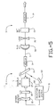
- Fig. 5 illustrates utilization of the oscillator/amplifier system according to the present invention in an injection seeded system.
- the injection seeded oscillator/amplifier includes all the same components as shown in Fig. 3 with some additions. Further, the output coupler is explicitly shown to be a radially variable reflectivity output coupler 50.
- the oscillator 10 is injection seeded using the injection seeding system 51 which consists of a small CW:YAG laser with a milliwatt or two power at 160 nm and a Faraday isolator preventing feedback from the oscillator 10.
- the system generates the seed beam along path 52 and is reflected by reflector 53 into the polarizer 16.
- Polarizer 16 directs the seeding beam through the Pockels cell 17 to high reflector 12 and back through the medium 14. This induces a pure longitudinal mode in the oscillator 10.
- the injection seeding system 51 further includes a dither control system for the high reflector 12.
- the high reflector 12 may be dither mounted and its position controlled to match the longitudinal mode of the oscillator 10 with the frequency of the seeding beam 52.
- Utilization of the quarter waveplates does not affect the design of resonators according to the present invention. Accordingly, they may be inserted if desired. However, it is found that they are unnecessary. It is believed that they are unnecessary because the medium 14 is operated with considerable stress induced birefringence which induces sufficient ellipticity in the beam travelling through the medium 14, that spatial hole burning does not reach significant levels.
- matching quarter waveplates should be placed around the amplifying medium 19.
- the present invention provides an oscillator/amplifier laser in which compensation for thermally induced birefringence in the gain medium of the oscillator is accomplished by offsetting thermally induced birefringence in the gain medium of the amplifier. Utilizing the present invention, it is found that no intracavity compensation is required for thermally induced birefringence in the oscillator, and no compensation outside the oscillator cavity is required for thermally induced birefringence in the amplifier gain medium.
Landscapes
- Physics & Mathematics (AREA)
- Electromagnetism (AREA)
- Engineering & Computer Science (AREA)
- Plasma & Fusion (AREA)
- Optics & Photonics (AREA)
- Lasers (AREA)
Applications Claiming Priority (4)
| Application Number | Priority Date | Filing Date | Title |
|---|---|---|---|
| US31273489A | 1989-02-17 | 1989-02-17 | |
| US312734 | 1989-02-17 | ||
| US07/358,714 US4955725A (en) | 1989-02-17 | 1989-05-26 | Laser oscillator/amplifier with compensation for stress birefringence |
| US358714 | 1989-05-26 |
Publications (2)
| Publication Number | Publication Date |
|---|---|
| EP0383638A2 true EP0383638A2 (fr) | 1990-08-22 |
| EP0383638A3 EP0383638A3 (fr) | 1991-10-02 |
Family
ID=26978523
Family Applications (1)
| Application Number | Title | Priority Date | Filing Date |
|---|---|---|---|
| EP19900301759 Withdrawn EP0383638A3 (fr) | 1989-02-17 | 1990-02-19 | Oscillateur-amplificateur laser avec compensation de la biréfringence induite par contrainte |
Country Status (3)
| Country | Link |
|---|---|
| US (1) | US4955725A (fr) |
| EP (1) | EP0383638A3 (fr) |
| JP (1) | JPH033288A (fr) |
Cited By (8)
| Publication number | Priority date | Publication date | Assignee | Title |
|---|---|---|---|---|
| FR2673491A1 (fr) * | 1991-03-01 | 1992-09-04 | Bourgogne Universite | Resonateur optique et oscillateur laser en anneau a elements polarisants. |
| WO1995022187A1 (fr) * | 1994-02-15 | 1995-08-17 | Coherent, Inc. | Systeme permettant de minimiser la depolarisation d'un faisceau laser due a la birefringence induite par la chaleur |
| EP1511134A3 (fr) * | 2003-08-29 | 2006-08-02 | CESI-Centro Elettrotecnico Sperimentale Italiano Giacinto Motta S.p.A. | Oscillateur laser à impulsions, à mode longitudinal unique, à frequence stabilisée, ainsi que la méthode d'opération correspondant |
| EP1969686A4 (fr) * | 2005-12-05 | 2011-08-10 | Adelaide Res & Innovation Pty | Laser declenche |
| RU2465698C2 (ru) * | 2011-01-17 | 2012-10-27 | Учреждение Российской академии наук Институт прикладной физики РАН | Устройство для компенсации термонаведенной деполяризации в поглощающем оптическом элементе лазера |
| RU2527257C1 (ru) * | 2013-02-12 | 2014-08-27 | Федеральное государственное бюджетное учреждение науки Институт прикладной физики Российской академии наук (ИПФ РАН) | Компенсатор термонаведенной деполяризации в поглощающем оптическом элементе лазера |
| EP2800212A1 (fr) * | 2013-05-03 | 2014-11-05 | Fotona d.d. | Procédé pour faire fonctionner un système de laser |
| EP3712664A1 (fr) | 2019-03-20 | 2020-09-23 | Uab "Ekspla" | Compensateur de dépolarisation |
Families Citing this family (15)
| Publication number | Priority date | Publication date | Assignee | Title |
|---|---|---|---|---|
| GB8912765D0 (en) * | 1989-06-02 | 1989-07-19 | Lumonics Ltd | A laser |
| CA2072070A1 (fr) * | 1990-01-11 | 1991-07-12 | Harold M. Epstein | Proprietes d'un materiau |
| JPH0537049A (ja) * | 1991-07-30 | 1993-02-12 | Hoya Corp | 固体レーザ装置 |
| US5197074A (en) * | 1991-12-26 | 1993-03-23 | Electro Scientific Industries, Inc. | Multi-function intra-resonator loss modulator and method of operating same |
| US5272560A (en) * | 1992-03-30 | 1993-12-21 | Hewlett-Packard Company | Variable spectral width multiple pass optical noise source |
| US5237331A (en) * | 1992-05-08 | 1993-08-17 | Henderson Sammy W | Eyesafe coherent laser radar for velocity and position measurements |
| US5361268A (en) * | 1993-05-18 | 1994-11-01 | Electro Scientific Industries, Inc. | Switchable two-wavelength frequency-converting laser system and power control therefor |
| US5555254A (en) * | 1993-11-05 | 1996-09-10 | Trw Inc. | High brightness solid-state laser with zig-zag amplifier |
| US5467214A (en) * | 1993-11-12 | 1995-11-14 | Trw Inc. | Birefringence-compensated alignment-insensitive frequency doubler |
| US5822345A (en) * | 1996-07-08 | 1998-10-13 | Presstek, Inc. | Diode-pumped laser system and method |
| US6210864B1 (en) | 1998-10-06 | 2001-04-03 | Presstek, Inc. | Method and apparatus for laser imaging with multi-mode devices and optical diffusers |
| EP1089403A1 (fr) * | 1999-09-28 | 2001-04-04 | Enel Societa'per Azioni | Laser déclanché à mode longitudinal unique |
| US6633596B1 (en) * | 2000-05-31 | 2003-10-14 | University Corporation For Atmospheric Research | Frequency stable pulsed laser |
| US11588293B2 (en) | 2017-11-21 | 2023-02-21 | Taiwan Semiconductor Manufacturing Co., Ltd. | Methods and systems for aligning master oscillator power amplifier systems |
| EP3588699A1 (fr) * | 2018-06-29 | 2020-01-01 | TRUMPF Schweiz AG | Système laser permettant de générer des impulsions laser |
Family Cites Families (5)
| Publication number | Priority date | Publication date | Assignee | Title |
|---|---|---|---|---|
| US4276518A (en) * | 1978-05-01 | 1981-06-30 | The United States Of America As Represented By The Secretary Of The Navy | Optical oscillator |
| US4360925A (en) * | 1980-02-25 | 1982-11-23 | Quanta Ray, Inc. | Laser employing an unstable resonator having an output transmissive mirror |
| WO1986003066A1 (fr) * | 1984-11-09 | 1986-05-22 | The Commonwealth Of Australia Care Of The Assistan | Compensation de birefringence dans des lasers couples par polarisation |
| IL78936A (en) * | 1986-05-27 | 1990-02-09 | Electro Optics Ind Ltd | Laser apparatus |
| US4752931A (en) * | 1986-08-04 | 1988-06-21 | Lightwave Electronics Co. | Pulse shaper for an electro-optically Q-switched seeded laser |
-
1989
- 1989-05-26 US US07/358,714 patent/US4955725A/en not_active Expired - Lifetime
-
1990
- 1990-02-16 JP JP2035982A patent/JPH033288A/ja active Pending
- 1990-02-19 EP EP19900301759 patent/EP0383638A3/fr not_active Withdrawn
Cited By (11)
| Publication number | Priority date | Publication date | Assignee | Title |
|---|---|---|---|---|
| FR2673491A1 (fr) * | 1991-03-01 | 1992-09-04 | Bourgogne Universite | Resonateur optique et oscillateur laser en anneau a elements polarisants. |
| WO1995022187A1 (fr) * | 1994-02-15 | 1995-08-17 | Coherent, Inc. | Systeme permettant de minimiser la depolarisation d'un faisceau laser due a la birefringence induite par la chaleur |
| US5504763A (en) * | 1994-02-15 | 1996-04-02 | Coherent, Inc. | System for minimizing the depolarization of a laser beam due to thermally induced birefringence |
| EP1511134A3 (fr) * | 2003-08-29 | 2006-08-02 | CESI-Centro Elettrotecnico Sperimentale Italiano Giacinto Motta S.p.A. | Oscillateur laser à impulsions, à mode longitudinal unique, à frequence stabilisée, ainsi que la méthode d'opération correspondant |
| EP1969686A4 (fr) * | 2005-12-05 | 2011-08-10 | Adelaide Res & Innovation Pty | Laser declenche |
| RU2465698C2 (ru) * | 2011-01-17 | 2012-10-27 | Учреждение Российской академии наук Институт прикладной физики РАН | Устройство для компенсации термонаведенной деполяризации в поглощающем оптическом элементе лазера |
| RU2527257C1 (ru) * | 2013-02-12 | 2014-08-27 | Федеральное государственное бюджетное учреждение науки Институт прикладной физики Российской академии наук (ИПФ РАН) | Компенсатор термонаведенной деполяризации в поглощающем оптическом элементе лазера |
| EP2800212A1 (fr) * | 2013-05-03 | 2014-11-05 | Fotona d.d. | Procédé pour faire fonctionner un système de laser |
| US9025625B2 (en) | 2013-05-03 | 2015-05-05 | Fotona D.D. | Method for operating a laser system |
| EP3712664A1 (fr) | 2019-03-20 | 2020-09-23 | Uab "Ekspla" | Compensateur de dépolarisation |
| LT6781B (lt) | 2019-03-20 | 2020-11-25 | Uab "Ekspla" | Depoliarizacijos kompensatorius |
Also Published As
| Publication number | Publication date |
|---|---|
| US4955725A (en) | 1990-09-11 |
| EP0383638A3 (fr) | 1991-10-02 |
| JPH033288A (ja) | 1991-01-09 |
Similar Documents
| Publication | Publication Date | Title |
|---|---|---|
| US4955725A (en) | Laser oscillator/amplifier with compensation for stress birefringence | |
| US5022033A (en) | Ring laser having an output at a single frequency | |
| US4872177A (en) | Laser diode pumped solid state laser | |
| US4656635A (en) | Laser diode pumped solid state laser | |
| US4756003A (en) | Laser diode pumped solid state laser | |
| US5504763A (en) | System for minimizing the depolarization of a laser beam due to thermally induced birefringence | |
| US4701929A (en) | Laser diode pumped solid state laser | |
| US8207474B2 (en) | Self-seeded single-frequency laser peening method | |
| US5530582A (en) | Fiber source for seeding an ultrashort optical pulse amplifier | |
| CN1328831C (zh) | 主被动调q单纵模激光器 | |
| US6373876B1 (en) | Single mode oscillator for a laser peening laser | |
| Baer et al. | Performance of diode-pumped Nd: YAG and Nd: YLF lasers in a tightly folded resonator configuration | |
| Kasinski et al. | One joule output from a diode-array-pumped Nd: YAG laser with side-pumped rod geometry | |
| EP0823143B1 (fr) | Laser pompe a diode utilisant des cristaux a forte focalisation thermique | |
| US4918395A (en) | Multipass laser amplifier with at least one expanded pass | |
| US5050175A (en) | Pulsed power laser with mopa structure with nonlinear energy transfer medium | |
| US4858239A (en) | Laser system | |
| JPH04229690A (ja) | 弱吸収レーザ材をポンピングするための装置及び方法 | |
| Yanovsky et al. | Compact, single-frequency, high-power Nd: glass laser | |
| Dyer et al. | High-power 80-ns transform-limited Nd: YAG laser | |
| Varnavsky et al. | Passively mode-locked Nd: YAG and ruby lasers with high brightness per unit active volume | |
| Dehn et al. | Phase conjugation for high-power solid state lasers with repetition rates in the kHz range | |
| Rapaport et al. | High-brightness alexandrite laser | |
| Bianchi et al. | Characterization of a modified SFUR Nd: YAG oscillator in various pulsed regimes | |
| Norman et al. | Advanced pulse generator and preamplifier for the HELEN laser |
Legal Events
| Date | Code | Title | Description |
|---|---|---|---|
| PUAI | Public reference made under article 153(3) epc to a published international application that has entered the european phase |
Free format text: ORIGINAL CODE: 0009012 |
|
| AK | Designated contracting states |
Kind code of ref document: A2 Designated state(s): DE FR GB |
|
| PUAL | Search report despatched |
Free format text: ORIGINAL CODE: 0009013 |
|
| AK | Designated contracting states |
Kind code of ref document: A3 Designated state(s): DE FR GB |
|
| RAP1 | Party data changed (applicant data changed or rights of an application transferred) |
Owner name: SPECTRA-PHYSICS LASERS, INC. |
|
| 17P | Request for examination filed |
Effective date: 19920331 |
|
| 17Q | First examination report despatched |
Effective date: 19931102 |
|
| STAA | Information on the status of an ep patent application or granted ep patent |
Free format text: STATUS: THE APPLICATION IS DEEMED TO BE WITHDRAWN |
|
| 18D | Application deemed to be withdrawn |
Effective date: 19940315 |