EP0383719A2 - Enthaarungsvorrichtung - Google Patents
Enthaarungsvorrichtung Download PDFInfo
- Publication number
- EP0383719A2 EP0383719A2 EP90630042A EP90630042A EP0383719A2 EP 0383719 A2 EP0383719 A2 EP 0383719A2 EP 90630042 A EP90630042 A EP 90630042A EP 90630042 A EP90630042 A EP 90630042A EP 0383719 A2 EP0383719 A2 EP 0383719A2
- Authority
- EP
- European Patent Office
- Prior art keywords
- hair
- discs
- plucking
- spaces
- plucking element
- Prior art date
- Legal status (The legal status is an assumption and is not a legal conclusion. Google has not performed a legal analysis and makes no representation as to the accuracy of the status listed.)
- Ceased
Links
- 210000004209 hair Anatomy 0.000 title claims abstract description 82
- 208000002271 trichotillomania Diseases 0.000 claims abstract description 69
- 230000008878 coupling Effects 0.000 claims abstract description 17
- 238000010168 coupling process Methods 0.000 claims abstract description 17
- 238000005859 coupling reaction Methods 0.000 claims abstract description 17
- 239000000463 material Substances 0.000 claims abstract description 16
- 230000033001 locomotion Effects 0.000 claims abstract description 14
- 230000002951 depilatory effect Effects 0.000 claims abstract description 13
- 239000004033 plastic Substances 0.000 claims abstract description 9
- 239000007779 soft material Substances 0.000 claims abstract description 5
- 238000013461 design Methods 0.000 claims description 21
- 238000000034 method Methods 0.000 claims description 5
- 239000002184 metal Substances 0.000 claims description 3
- 239000004677 Nylon Substances 0.000 claims description 2
- 229920001778 nylon Polymers 0.000 claims description 2
- 239000013536 elastomeric material Substances 0.000 claims 1
- 238000012546 transfer Methods 0.000 abstract description 3
- 238000010276 construction Methods 0.000 description 9
- 238000004519 manufacturing process Methods 0.000 description 4
- 238000012986 modification Methods 0.000 description 2
- 230000004048 modification Effects 0.000 description 2
- 230000000717 retained effect Effects 0.000 description 2
- 229910000831 Steel Inorganic materials 0.000 description 1
- 208000027418 Wounds and injury Diseases 0.000 description 1
- 238000013459 approach Methods 0.000 description 1
- 238000005452 bending Methods 0.000 description 1
- 230000005540 biological transmission Effects 0.000 description 1
- 238000004140 cleaning Methods 0.000 description 1
- 230000006378 damage Effects 0.000 description 1
- 230000007547 defect Effects 0.000 description 1
- 239000013013 elastic material Substances 0.000 description 1
- 210000003746 feather Anatomy 0.000 description 1
- 230000003779 hair growth Effects 0.000 description 1
- 208000014674 injury Diseases 0.000 description 1
- 238000007689 inspection Methods 0.000 description 1
- 230000000149 penetrating effect Effects 0.000 description 1
- 238000005096 rolling process Methods 0.000 description 1
- 239000010959 steel Substances 0.000 description 1
- 238000004804 winding Methods 0.000 description 1
Images
Classifications
-
- A—HUMAN NECESSITIES
- A45—HAND OR TRAVELLING ARTICLES
- A45D—HAIRDRESSING OR SHAVING EQUIPMENT; EQUIPMENT FOR COSMETICS OR COSMETIC TREATMENTS, e.g. FOR MANICURING OR PEDICURING
- A45D26/00—Hair-singeing apparatus; Apparatus for removing superfluous hair, e.g. tweezers
- A45D26/0023—Hair-singeing apparatus; Apparatus for removing superfluous hair, e.g. tweezers with rotating clamping elements
- A45D26/0028—Hair-singeing apparatus; Apparatus for removing superfluous hair, e.g. tweezers with rotating clamping elements with rotating discs or blades
Definitions
- the present invention relates to motorized depilatory devices for removing unwanted skin hair, and more particularly, to a new and useful hair removal device which plucks out skin hair based on the operation of a novel coupled-disc element.
- the helical spring may break during use, creating a hazard of puncturing and penetrating the skin over which it passes.
- Another disadvantage to this design is the transverse deflection of hair due to lateral movement of the spaces between the helical spring loops which rotate in spiral fashion. This tends to limit the degree of certainty that hairs will be plucked, as shorter hairs will not remain within a given loop as it moves laterally.
- a motor-powered depilatory device which employs a hair-plucker body comprising a plastic or rubber cylindrical member having a smooth outer surface formed with a plurality of partially circumferential slits.
- the cylindrical member is rotatable about its longitudinal axis and is supported in an arcuate position such that the slits open and close during rotation, trapping and plucking hairs therein. Because they are only partially circumferential , the slits are effective only during a portion of the rotation, reducing overall efficiency.
- the soft plastic or rubber material By use of the soft plastic or rubber material, a greater contact area is afforded the individual hairs which are trapped within the slits of the cylindrical element. While this represents an important departure from the helical spring plucking operation, the soft plastic or rubber material also exhibits the "winding" phenomenon because of its flexibility. Thus, this design is also subject to increasing the pain associated with plucking of individual hairs.
- the material is soft and has a high friction coefficient, friction with the skin is increased, requiring an increased motor rating for maintaining a given rotational speed.
- the partially circumferential slits in the plucker body constitute weak points, causing it to "tear" apart and limiting its durability.
- a depilatory device comprising a series of adjacent, closely-spaced hair-plucking discs driven by an electric motor housed within a casing.
- the discs are periodically deformed during their rotation, such that adjacent ones thereof are pressed together to pluck hairs which may have become trapped between them when the unit is passed over the skin.
- a drawback to this design is associated with the fact that the discs close only periodically, making the plucking action inefficient by limiting it to a short time interval.
- US Patent 2,900,661 to Schnell discloses a plucking device for feathers, hairs or the like in which at least one pair of discs rotate at an angle to each other and converge at one contact point whereat hairs are plucked.
- the disadvantage associated with this design stems from the large spacing between disc pairs, which reduces efficiency, in addition to being expensive and complicated.
- a motor-powered depilatory device comprising: a manually-held housing; motor means disposed in said housing; and a longitudinal hair-plucking element coupled to said motor means and being rotatably supported by said housing in arched configuration, said hair-plucking element comprising a plurality of adjacent, axially-aligned discs each having a hole formed centrally therein, the holes of said plurality of discs defining a cavity through which there extends a tensioning means, each of said discs having formed on at least one side thereof at least one substantially perpendicular projection and on the other side thereof at least one corresponding recess for engaging said projection of an adjacently-disposed disc such that said plurality of discs are mechanically coupled together by said tensioning means which flexibly retains them adjacent one another under a predetermined tension to provide rotational coupling along the length of said hair-plucking element, said arched configuration providing said hair-plucking element with spaces on a convex side
- the hair-plucking element is provided as a plurality of discs adjacently coupled in column form.
- a central spine comprising a pre-tensioned spring
- the discs are maintained adjacent one another under tension, while the column is bendable.
- the hair-plucking element transfers the rotation via rotational coupling of the adjacent discs in the column.
- the rotational motion is transferred across its entire length.
- the rotationally-coupled discs are made of relatively rigid plastic material, and are mechanically coupled by a set of tab-like projections on each disc surface, which engage matching recesses in adjacent discs.
- adjacent discs are made of a soft material with a high friction coefficient and are rotationally coupled by friction between them.
- the arched configuration of the hair-plucking element provides spaces between adjacent discs on a convex side, and hair trapped in these spaces is plucked when they close upon rotation of the hair-plucking element toward its concave side.
- manufacture of the mechanically-coupled plurality of discs from relatively rigid material eliminates the tendency for axial "twisting", thereby reducing the time interval between grasping and plucking of individual hairs to a minimum.
- hair removal is quick, smooth, efficient and substantially less painful than in prior art designs.
- a feature of the inventive hair-plucking element design is the provision of tapered, outer circumferential edges on the adjacent discs. When these discs converge and close on the concave side during rotation, individual hairs are trapped between facing sides of the discs which are parallel one another. This provides a greater surface area of contact with the hair, which results in a greater degree of certainty that individual hairs which become trapped will in fact be plucked from the skin. This is an important advantage over the helical spring construction discussed in the background, where essentially a single point of contact is made with an individual hair, increasing the likelihood of tearing rather than plucking it.
- the hair-plucking element of the present invention provides a durable design capable of repeated usage. Because of its relative rigidity, contact between the coupled discs and individual hairs is made along a line corresponding to the hair's length, rather than at a singular point as occurs with the helical spring approach. The increased surface area over which individual hairs are grasped ensures a greater degree of certainty that plucking rather than tearing will occur.
- inventive hair-plucking element is constructed of individual discs, transfer of rotational power when frictionally coupled does not subject it to the creation of weak points in the spaces between the coupled discs. This is an advantage over the design of the Gross patent, where the partially circumferential slits constitute weak points which tend to "tear" the soft rubber or plastic material, reducing its durability.
- the hair removal device of the invention is simply constructed, allowing for cost-effective production.
- hair-plucking element is arranged in an arched configuration whereby its convex side faces inwardly toward the housing.
- the mechanically-coupled discs are provided with different diameters and angled edges, such that a relatively straight line is provided between them on the concave side of the arched hair-plucking element column.
- the discs are retained together in the column by end clamps, which are respectively seated in a pair of flexible end supports formed in the housing.
- the straight line shape of its concave side may be placed directly alongside the skin near the contact points where the hair is trapped between the discs. This enables plucking of very short hair, without regard to the disc diameter, enabling use of larger diameter discs.
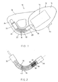
- Device 10 comprises a housing 12, a motor compartment 14 and a miniature electric motor 16 disposed therein. Extending from and integrally formed with housing 12 there is provided a substantially flat, shaped support 18 having an arched slot 20 formed therein proximate its lower edge 22. Electric motor 16 may be battery-operated under control of on-off switch 24, or it may be supplied with power by a conventional cord and plug connection to a household electrical system. A shaft 26 of motor 16 is keyed, and has seated thereon a coupling 28 which protrudes through an opening of motor compartment 14 and into one end of arched slot 20.
- Coupling 28 forms one end of a hair-plucking element 30 which is disposed in arched slot 20, a coupling 32 at the other end of element 30 being supported by a bearing 34 which is mounted to support 18.
- hair-plucking element 30 comprises a plurality of individual discs 36 which are mechanically or frictionally coupled together, such that when powered by motor 16, rotational motion of coupling 28 is transferred via coupled discs 36 to coupling 32. Rotational motion of the individual discs 36 provides the hair plucking operation when element 30 assumes the arched configuration as shown.
- discs 36 are manufactured of a relatively rigid plastic material.
- FIG. 2 there is shown a top view of the preferred embodiment of hair-plucking element 30 of Fig. 1 in the arched configuration, revealing further construction details.
- adjacent ones of discs 36 are coupled by substantially perpendicular projections 38 extending from one side of a disc about the center thereof, which engage recesses 40 formed in an adjacent disc 36.
- Engagement of projections 38 in the recesses 40 on adjacent discs 36 is assured by provision of a centrally-disposed tensioning means 41 which extends through a cavity defined by the centrally-formed holes in each of discs 36.
- tensioning means 41 comprises a spring having its ends retained by couplings 28 and 32.
- tensioning means 41 could be any suitable elastic material, such as rubber, nylon cord, steel cable and the like.
- tensioning means 41 maintains discs 36 adjacent one another. Since projections 38 engage the recesses on adjacent discs 36 in sliding fashion, when hair-plucking element 30 is provided with an arched configuration as shown, projections 38 are adjusted accordingly, but rotational coupling is maintained. As shown, the arched configuration of hair-plucking element 30 provides spaces 42 on its convex side between individual discs 36.
- Operation of hair removal device 10 proceeds by passage of hair-plucking element 30 over the skin where it is desired to remove unwanted hair. As it is passed over the skin, individual hairs 46 are trapped within spaces 42. Due to the rotational motion provided by motor 16, spaces 42 between individual discs 36 of hair-plucking element 30 close on the concave side thereof, at which point trapped hairs are plucked from the skin.
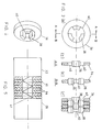
- a top view of a disc 36 is shown, revealing the arrangement of projections 38 and recesses 40.
- three projections 38 are provided in symmetrical arrangement about the center of disc 36, such that three recesses are defined between projections 38.
- Figs. 3b-c show, respectively, a cross-section of disc 36 taken along respective section lines A-A and B-B, revealing the arrangement of projections 38 and recesses 40.
- Fig. 3d shows a cross-section of a plurality of adjacent discs 36 forming element 30, in which details of the mechanical coupling between projections 38 and recesses 40 are visible.
- Fig. 4 shows a perspective view of an individual one of discs 36, in which projections 38 and recesses 40 are visible. It will be appreciated that while Figs. 3b-d show projections 38 extending from either side of disc 36, Figs. 2 and 7a may be considered as an alternative design, in which projections 38 extend from only one side of a disc 36. In either case, in accordance with the principles of the invention, where projections 38 and recesses 40 are provided, they are arranged such as to insure rotational coupling between adjacent discs 36.
- Fig. 5 there is shown a schematic illustration of another alternative embodiment of hair-plucking element 30.
- discs 36 are made of soft material having a high friction coefficient, and are rotationally coupled by friction between adjacent ones thereof under the pre-tension of tensioning means 41, without the provision of projections 38 and recesses 40.
- Figs. 6a-b there is shown a typical arrangement of a prior art design using a helical spring 44 in grasping and plucking individual hairs 46 from the skin 48. Because the contact between the spring 44 and the individual hair 46 is provided essentially at a single point, the likelihood of tearing rather than plucking the hair 46 from the skin 48 is increased. This is illustrated more clearly in the enlarged view of Fig. 6b, where it is seen that a hair 46 trapped between loops of a helical spring 44 is "pinched", forming a weak point. As the pulling tension at this point increases, so does the likelihood that the hair 46 will be torn or cut.
- Figs. 7a-b illustrate, respectively, general and enlarged views of a grasping action of a single hair 46 between faces of a pair of discs 36 used in construction of the inventive hair-plucking element 30 of Fig. 2.
- disc 36 has a tapered outer circumferential edge 50, which provides unique advantages in operation for grasping and pulling of individual hairs as described further herein.
- contact with the individual hair 46 is made in greater proximity to its root by use of the inventive hair-plucking element 30.
- the rigid material used for construction of mechanically-coupled hair-plucking element 30 ensures that during rotation, it does not "twist” as it grabs and pulls individual hairs 46 from the skin 48. Rotational motion is evenly transferred all across the length of hair-plucking element 30 by virtue of the mechanically-coupled discs 36.
- By provision of tapered edges 50 on each of discs 36 individual hairs 46 trapped between them have a portion of their length in contact with the surface area of tapered edges 50, which are substantially parallel. This ensures quick, clean and efficient plucking of hairs 46 with an improved degree of certainty over that of prior art designs.
- Fig. 7b illustrates the extent of the tapered edge 50 surface area over which contact is made with individual hairs 46 in the grasping and plucking operation.
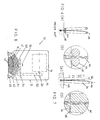
- hair-plucking element 30 is constructed of mechanically-coupled discs 36 made of relatively rigid material, these may be alternated with frictionally-coupled discs formed of flexible material. Flexible discs tend to conform to the shape of individual hairs 46 as they are grasped during operation. Thus, the surface area of contact is increased, along with the likelihood of successful grasping and plucking of individual hairs 46 from the skin 48.
- hair-plucking element 30 is arranged in an arched configuration whereby its convex side faces inwardly toward housing 12.
- Discs 51 are mechanically coupled and designed with different diameters and angled edges so as to provide a relatively straight line on the concave side of the arched configuration, such that a difference in the arc curvatures exists between the concave and convex sides.
- housing 12 is designed with motor compartment 14 directly above hair-plucking element 30.
- a transmission belt 52 is provided between motor 16 shaft 26 and a drive shaft 54 on which there is mounted a drive gear 56, which meshes with a toothed disc 58 provided in the middle of the hair-plucking element 30 column, for driving rotational motion.
- An end clamp 60 provided at either end of hair-plucking element 30 is seated in a respective one of a pair of flexible end supports 62 formed in housing 12. Flexible end supports 62 may be spread apart to enable easy removal of hair-plucking element 30 for cleaning or replacement.
- tensioning means 41 maintains discs 51 mechanically coupled adjacent one another.
- Tensioning means 41 may be pre-formed of spring metal to fix it in arched configuration, so that discs 51 rotate thereon.
- hair removal device 10 proceeds as before with hair-plucking element 30 being driven rotationally by motor 16, while it is passed over the skin.
- hair-plucking element 30 may be placed against the skin such that spaces 42 close between discs 51 at a contact point which faces the skin.
- This enables use of discs 51 having larger diameters, since this does not interfere with effective placement close to the skin of the contact point between discs 51.
- Larger diameter discs 51 are advantageous in that at the convex side of hair-plucking element 30, spaces 42 between them open wider, virtually “throwing” trapped hairs out, due to the greater centrifugal force of the large diameter discs.
- the straight line design of the alternative embodiment of Fig. 8 provides several advantages. The most important of these is that whereas with the normal arc curvature design on the concave side, the "side" of the arc is placed against the skin, with the straight line design, the contact point in spaces 42 between discs 51 is placed closer to the skin. Thus, instead of requiring smaller discs 36 to place the contact point close to the skin, larger discs 51 are usable.
Landscapes
- Dry Shavers And Clippers (AREA)
- Cosmetics (AREA)
- Brushes (AREA)
Applications Claiming Priority (2)
| Application Number | Priority Date | Filing Date | Title |
|---|---|---|---|
| IL89290A IL89290A (en) | 1989-02-14 | 1989-02-14 | Hair removal device |
| IL89290 | 1989-02-14 |
Publications (2)
| Publication Number | Publication Date |
|---|---|
| EP0383719A2 true EP0383719A2 (de) | 1990-08-22 |
| EP0383719A3 EP0383719A3 (de) | 1991-05-08 |
Family
ID=11059688
Family Applications (1)
| Application Number | Title | Priority Date | Filing Date |
|---|---|---|---|
| EP19900630042 Ceased EP0383719A3 (de) | 1989-02-14 | 1990-02-14 | Enthaarungsvorrichtung |
Country Status (4)
| Country | Link |
|---|---|
| US (2) | US4935024A (de) |
| EP (1) | EP0383719A3 (de) |
| JP (1) | JPH0329605A (de) |
| IL (1) | IL89290A (de) |
Cited By (4)
| Publication number | Priority date | Publication date | Assignee | Title |
|---|---|---|---|---|
| WO2001032047A1 (en) * | 1998-07-09 | 2001-05-10 | K. I. S. Ltd. | Hair removal device with disc assembly |
| WO2001060196A1 (en) * | 1998-07-09 | 2001-08-23 | K.I.S.Ltd. | Hair removal device with vibrating assembly |
| EP1857012A1 (de) | 2006-05-18 | 2007-11-21 | Faco S.A. | Monolithisches Epilationsgerät |
| US8608756B2 (en) | 2005-05-02 | 2013-12-17 | Koninklijke Philips N.V. | Disc for an epilating apparatus disc assembly |
Families Citing this family (26)
| Publication number | Priority date | Publication date | Assignee | Title |
|---|---|---|---|---|
| IL89290A (en) * | 1989-02-14 | 1992-08-18 | Dolev Moshe | Hair removal device |
| US5470332A (en) * | 1989-12-21 | 1995-11-28 | Thomas L. Mehl, Sr. | System for permanent removal of multiple hairs |
| US5100414A (en) * | 1991-03-05 | 1992-03-31 | Moshe Dolev | Rotary head multi-spring hair removal device |
| US5100413A (en) * | 1991-03-05 | 1992-03-31 | Moshe Dolev | Rotary head multi-tweezer hair removal device |
| IL103071A (en) * | 1991-09-10 | 1995-11-27 | Philips Electronics Nv | Install a disc plucking hair |
| IL103073A (en) * | 1991-09-10 | 1995-11-27 | Philips Electronics Nv | Install a disc-type hair puller |
| USD352109S (en) | 1991-10-23 | 1994-11-01 | Kanan Saib | Cosmetic hair extractor |
| DE69230781T2 (de) * | 1991-12-23 | 2000-09-21 | Koninkl Philips Electronics Nv | Haarentfernungsgerät mit verdrehender Wirkung |
| US5281233A (en) * | 1993-02-12 | 1994-01-25 | Moshe Dolev | Disc assembly hair remover |
| US6159222A (en) * | 1998-03-17 | 2000-12-12 | Soft Lines Ltd. | Device for hair removal |
| US6824546B1 (en) * | 1998-07-09 | 2004-11-30 | Soft Lines, Ltd. | Hair removal device with disc and vibration assemblies |
| US6824461B1 (en) * | 2003-05-19 | 2004-11-30 | Moshe Dolev | Hair depilating device and method for improved depilating coverage |
| IL159483A0 (en) * | 2003-12-21 | 2004-06-01 | Epilady 2000 Llc | Hair removal system |
| JP4431610B2 (ja) * | 2005-02-06 | 2010-03-17 | ライシェン リウ | 電気除毛器 |
| EP2106718B1 (de) * | 2005-04-18 | 2010-11-17 | Koninklijke Philips Electronics N.V. | Enthaarungsgerät |
| US20070093853A1 (en) * | 2005-10-26 | 2007-04-26 | Epilady 2000, L.L.C | Multi-tweezer hair removal apparatus and method |
| US20070239174A1 (en) * | 2006-04-06 | 2007-10-11 | Francis Yiu | Epilator with Glide Tweezers |
| CN101219011B (zh) * | 2007-01-12 | 2011-12-28 | 游图明 | 结构改进的拔毛器 |
| EP1994851A1 (de) * | 2007-05-22 | 2008-11-26 | Hong Kong Data Analysis Company Limited | Epiliergerät |
| US20100198233A1 (en) * | 2007-07-18 | 2010-08-05 | Yehuda Poran | Epilator head for trapping hair and epilator with such head |
| DE102008014946A1 (de) * | 2008-03-19 | 2009-09-24 | Ever Shine Technology Limited | Enthaarungsvorrichtung |
| US8246426B1 (en) * | 2010-11-16 | 2012-08-21 | Hanna Acquisition Corporation | Hog paddle and method of manufacturing the same |
| WO2015162455A1 (ru) * | 2014-04-23 | 2015-10-29 | Андрей ХАПАЛОВ | Эпилятор и сменная насадка для эпилятора |
| EP3375320B1 (de) | 2017-03-17 | 2019-11-20 | Epilady 2000 LLC | Epiliervorrichtung und verfahren |
| US11375794B1 (en) * | 2018-12-04 | 2022-07-05 | Studio 010 Inc. | Device for pulling nose and ear hair |
| USD1041077S1 (en) * | 2019-10-02 | 2024-09-03 | Catherine Newman | Instrument for removing fine hairs |
Family Cites Families (22)
| Publication number | Priority date | Publication date | Assignee | Title |
|---|---|---|---|---|
| US1232617A (en) * | 1916-01-25 | 1917-07-10 | John L Shipp | Spring hair-remover. |
| GB203970A (en) * | 1922-12-13 | 1923-09-20 | Charles Davis | Improvements in depilatory apparatus |
| US1743590A (en) * | 1928-11-14 | 1930-01-14 | Binz Matilde | Hair puller |
| CH179261A (fr) * | 1934-11-07 | 1935-08-31 | Macioce Michel | Appareil dépilatoire. |
| US2112230A (en) * | 1935-10-21 | 1938-03-29 | James M Stockett | Feather plucking machine |
| US2458911A (en) * | 1944-08-29 | 1949-01-11 | Kerr Ellen | Device for depilatory purposes |
| US2592484A (en) * | 1946-06-15 | 1952-04-08 | Moreton A Smith | Power-driven tweezer |
| US2496223A (en) * | 1946-07-13 | 1950-01-31 | Joseph C Lanzisera | Poultry plucker |
| US2423245A (en) * | 1946-11-09 | 1947-07-01 | Carl E Magnus | Method of and device for extracting hairs by using adhesive tape |
| US2486616A (en) * | 1947-11-22 | 1949-11-01 | Carl J Schubiger | Hair tweezer |
| CH268696A (de) * | 1948-09-02 | 1950-05-31 | Fischer Rudolf | Haarentfernungsapparat. |
| US2900661A (en) * | 1957-03-11 | 1959-08-25 | Schnell Carl | Plucking device for feathers, hairs or the like |
| FR2245314A1 (en) * | 1973-10-02 | 1975-04-25 | Amstutz Daniel | Mechanical device for depilation of superfluous hair - has two rotating bands which frictionally grip and pull out hairs |
| FR2307491A1 (fr) * | 1975-04-15 | 1976-11-12 | Dzikowski Francis | Appareil a epiler automatique |
| GB1508528A (en) * | 1975-12-09 | 1978-04-26 | Daar Y | Apparatus for plucking hair from skin |
| NL7805230A (nl) * | 1978-05-16 | 1979-11-20 | Philips Nv | Epileerapparaat. |
| IE54383B1 (en) * | 1982-08-20 | 1989-09-13 | Improver Corp | Apparatus for hair removal |
| FR2556939B1 (fr) * | 1983-12-22 | 1987-10-23 | Jean Alazet | Appareil a epiler |
| IL81779A0 (en) * | 1987-03-04 | 1987-10-20 | Gross Joseph | Depilatory device |
| IL81780A (en) * | 1987-03-04 | 1988-09-30 | Hair Remover Ltd | Depilatory device for removing hair |
| IL82002A0 (en) * | 1987-03-25 | 1987-10-20 | Gen Ideas & Prod Ltd | Depilatory device |
| IL89290A (en) * | 1989-02-14 | 1992-08-18 | Dolev Moshe | Hair removal device |
-
1989
- 1989-02-14 IL IL89290A patent/IL89290A/xx not_active IP Right Cessation
- 1989-04-19 US US07/340,529 patent/US4935024A/en not_active Expired - Fee Related
-
1990
- 1990-02-14 EP EP19900630042 patent/EP0383719A3/de not_active Ceased
- 1990-02-14 JP JP2033623A patent/JPH0329605A/ja active Pending
- 1990-02-26 US US07/484,768 patent/US5057115A/en not_active Expired - Fee Related
Cited By (5)
| Publication number | Priority date | Publication date | Assignee | Title |
|---|---|---|---|---|
| WO2001032047A1 (en) * | 1998-07-09 | 2001-05-10 | K. I. S. Ltd. | Hair removal device with disc assembly |
| WO2001060196A1 (en) * | 1998-07-09 | 2001-08-23 | K.I.S.Ltd. | Hair removal device with vibrating assembly |
| US8608756B2 (en) | 2005-05-02 | 2013-12-17 | Koninklijke Philips N.V. | Disc for an epilating apparatus disc assembly |
| EP1857012A1 (de) | 2006-05-18 | 2007-11-21 | Faco S.A. | Monolithisches Epilationsgerät |
| US8216251B2 (en) | 2006-05-18 | 2012-07-10 | Faco S.A. | Monolithic epilator |
Also Published As
| Publication number | Publication date |
|---|---|
| IL89290A (en) | 1992-08-18 |
| US5057115A (en) | 1991-10-15 |
| EP0383719A3 (de) | 1991-05-08 |
| JPH0329605A (ja) | 1991-02-07 |
| US4935024A (en) | 1990-06-19 |
| IL89290A0 (en) | 1989-09-10 |
Similar Documents
| Publication | Publication Date | Title |
|---|---|---|
| US5057115A (en) | Hair removal device with improved coupled-disc element | |
| KR950008304B1 (ko) | 탈모 장치 | |
| US5281233A (en) | Disc assembly hair remover | |
| US6176862B1 (en) | Hair-removing device with rotary roller equipped with pain-soothing device | |
| US6123713A (en) | Hair removal device with vibrating assembly | |
| US5011485A (en) | Depilatory device | |
| EP0292091A1 (de) | Enthaarungsgerät | |
| EP0101656A1 (de) | Enthaarungsgerät | |
| US5112341A (en) | Hair removal device with central multiple-tweezer element | |
| US5915391A (en) | Electric comb having oscillatory movement | |
| KR20040025684A (ko) | 전동칫솔의 브러시 섹션 | |
| EP0576561A1 (de) | Enthaarungsvorrichtung mit mehreren schraubenfedern und einem drehbaren kopf | |
| EP0342546A2 (de) | Enthaarungsvorrichtung | |
| US6585743B2 (en) | Hair depilating device utilizing mechanism to spirally align coupled-tweezer elements | |
| JPH02124104A (ja) | 電動脱毛装置 | |
| US20020128664A1 (en) | Manual depilatory device | |
| US20120035621A1 (en) | Hair removal device | |
| WO2001093767A1 (en) | Hair depilating device utilizing mechanism to spirally align coupled-tweezer elements | |
| EP0386327A2 (de) | Vorrichtung zum Enthaaren | |
| JP3271876B2 (ja) | 脱毛装置 | |
| JPH09121930A (ja) | 脱毛装置 | |
| JPH11187924A (ja) | 脱毛装置及びこれを用いた脱毛方法 | |
| JP3271852B2 (ja) | 脱毛装置 | |
| JPH038257Y2 (de) | ||
| WO1993014667A1 (en) | Rotary head spring-loaded tweezer hair removal device |
Legal Events
| Date | Code | Title | Description |
|---|---|---|---|
| PUAI | Public reference made under article 153(3) epc to a published international application that has entered the european phase |
Free format text: ORIGINAL CODE: 0009012 |
|
| AK | Designated contracting states |
Kind code of ref document: A2 Designated state(s): AT BE CH DE ES FR GB GR IT LI LU NL SE |
|
| PUAL | Search report despatched |
Free format text: ORIGINAL CODE: 0009013 |
|
| AK | Designated contracting states |
Kind code of ref document: A3 Designated state(s): AT BE CH DE ES FR GB GR IT LI LU NL SE |
|
| 17P | Request for examination filed |
Effective date: 19911022 |
|
| 17Q | First examination report despatched |
Effective date: 19930312 |
|
| STAA | Information on the status of an ep patent application or granted ep patent |
Free format text: STATUS: THE APPLICATION HAS BEEN REFUSED |
|
| 18R | Application refused |
Effective date: 19940714 |