EP0384100A2 - Power driven pliers-type tool holder for handling devices - Google Patents
Power driven pliers-type tool holder for handling devices Download PDFInfo
- Publication number
- EP0384100A2 EP0384100A2 EP90100068A EP90100068A EP0384100A2 EP 0384100 A2 EP0384100 A2 EP 0384100A2 EP 90100068 A EP90100068 A EP 90100068A EP 90100068 A EP90100068 A EP 90100068A EP 0384100 A2 EP0384100 A2 EP 0384100A2
- Authority
- EP
- European Patent Office
- Prior art keywords
- cam
- pliers
- tool carrier
- assigned
- cam track
- Prior art date
- Legal status (The legal status is an assumption and is not a legal conclusion. Google has not performed a legal analysis and makes no representation as to the accuracy of the status listed.)
- Granted
Links
Images


Classifications
-
- B—PERFORMING OPERATIONS; TRANSPORTING
- B21—MECHANICAL METAL-WORKING WITHOUT ESSENTIALLY REMOVING MATERIAL; PUNCHING METAL
- B21D—WORKING OR PROCESSING OF SHEET METAL OR METAL TUBES, RODS OR PROFILES WITHOUT ESSENTIALLY REMOVING MATERIAL; PUNCHING METAL
- B21D39/00—Application of procedures in order to connect objects or parts, e.g. coating with sheet metal otherwise than by plating; Tube expanders
- B21D39/03—Application of procedures in order to connect objects or parts, e.g. coating with sheet metal otherwise than by plating; Tube expanders of sheet metal otherwise than by folding
- B21D39/031—Joining superposed plates by locally deforming without slitting or piercing
-
- Y—GENERAL TAGGING OF NEW TECHNOLOGICAL DEVELOPMENTS; GENERAL TAGGING OF CROSS-SECTIONAL TECHNOLOGIES SPANNING OVER SEVERAL SECTIONS OF THE IPC; TECHNICAL SUBJECTS COVERED BY FORMER USPC CROSS-REFERENCE ART COLLECTIONS [XRACs] AND DIGESTS
- Y10—TECHNICAL SUBJECTS COVERED BY FORMER USPC
- Y10T—TECHNICAL SUBJECTS COVERED BY FORMER US CLASSIFICATION
- Y10T29/00—Metal working
- Y10T29/53—Means to assemble or disassemble
- Y10T29/53709—Overedge assembling means
- Y10T29/5377—Riveter
-
- Y—GENERAL TAGGING OF NEW TECHNOLOGICAL DEVELOPMENTS; GENERAL TAGGING OF CROSS-SECTIONAL TECHNOLOGIES SPANNING OVER SEVERAL SECTIONS OF THE IPC; TECHNICAL SUBJECTS COVERED BY FORMER USPC CROSS-REFERENCE ART COLLECTIONS [XRACs] AND DIGESTS
- Y10—TECHNICAL SUBJECTS COVERED BY FORMER USPC
- Y10T—TECHNICAL SUBJECTS COVERED BY FORMER US CLASSIFICATION
- Y10T29/00—Metal working
- Y10T29/53—Means to assemble or disassemble
- Y10T29/53796—Puller or pusher means, contained force multiplying operator
- Y10T29/5383—Puller or pusher means, contained force multiplying operator having fluid operator
Definitions
- the invention relates to a power-operated pliers-like tool holder for handling devices.
- a handling device commonly referred to as a “robot”, is to be understood as a device that can execute program-controlled movements in the direction of several degrees of freedom.
- a well-known example are automatic welding machines which place spot welds at predetermined positions on motor vehicle bodies.
- the body or, more generally, the workpiece is supported in a predetermined position, which provides a spatial reference coordinate system according to which the machine is programmed.
- both electrodes exert the same, oppositely directed forces on the workpiece so that it is not deformed, for example by a bending load.
- the object of the invention is to provide a tool carrier for handling devices of this type for carrying out work processes in which forces acting on one side can occur.
- the cam track head determines the course of movement of the individual (at least two) pliers links through the course of the respective cam tracks, but only a single drive needs to be provided.
- Figures 1 to 3 show a partially sectioned side view of a tool carrier according to the invention in three successive stages of the movement sequence.
- the sheets to be connected are supported on a die 14, while a punch cuts the sheets from the other side and penetrates them into the die cavity, after which the material which has passed through is spread out laterally; then the punch 16 is withdrawn again and the die is released from the workpiece.
- the tool carrier comprises a base 20 which can be attached to a working arm (not shown) of a handling device in a predetermined position, e.g. by screwing.
- the position of the base relative to the working axes of the handling device is thus fixed.
- the working arm can be displaced in the direction of an axis 22 and can pivot about this axis.
- the underside of the sheet 10 is the reference plane in which the axis 22 should lie, and that the base 20 is rotated about the axis 22 such that the axis 24 of the joint 26 runs parallel to this reference plane . If, as provided here, the axis 22 intersects the hinge axis 24 perpendicularly, the programming is simplified.
- joints can also be provided, which preferably have axes that are parallel to one another.
- Two pliers members 30 and 32 are pivotable about the axis 24, of which the pliers member 30 carries the die 14 and the pliers member 32 carries the punch 16.
- the tong sections are designed as two-armed levers. The free tool facing away from the die or die Each end is equipped with a cam follower 34, the engagement surface 36 of which is rounded.
- a working cylinder preferably a hydraulic cylinder 40, is mounted on the base, the piston of which carries a cam track head 42.
- the cam track head is interchangeable to adapt to different tools that can be mounted on the pliers links.
- the cam track head has cam tracks 44, 46, one for each tong member, the cam follower of which is held in contact with the associated cam track by means of a biasing spring 48.
- the tool carrier In the starting position according to FIG. 1, the tool carrier is in its open position, so that it can be moved along the axis 22 via the sheet metal angle 12 in the working position.
- the working cylinder 40 If the working cylinder 40 is then actuated, the pliers member 30 is first pivoted into its end position by the cam track 44, in which the die just comes to rest on the side of the sheet 10 facing it. At the same time, the stamp is steadily approached the sheet metal angle 12.
- the pliers member 30 stops (the corresponding section of the cam track 44 runs parallel to the reference plane), while the cam track 46 pivots the punch 16 into the position shown in FIG. 3, in which the joining process is finished.
- the movements of the tong links run in reverse order.
- pliers links can be actuated simultaneously.
- another pliers member could have an ejector element that detaches the workpiece from the die.
- one could dispense with the bias springs if the cam followers were guided in channel-like cam tracks.
Landscapes
- Engineering & Computer Science (AREA)
- Mechanical Engineering (AREA)
- Manipulator (AREA)
- Mounting, Exchange, And Manufacturing Of Dies (AREA)
- Automatic Assembly (AREA)
- Automatic Tool Replacement In Machine Tools (AREA)
- Scissors And Nippers (AREA)
- Processing Of Terminals (AREA)
- Gripping Jigs, Holding Jigs, And Positioning Jigs (AREA)
Abstract
Ein kraftbetriebener Werkzeugträger für Handhabungsgeräte umfaßt einen Sockel (20), an dem Zangenglieder (30, 32) angelenkt sind. Diese sind als zweiarmige Hebel ausgebildet und tragen am einen freien Ende ein Werkzeug (14, 16), am andern einen Nockenfolger (34). Ein allen Zangenglieden gemeinsam zugeordneter Nockenbahnkopf (42) ist hydraulisch verlagerbar und weist für jedes Zangenglied eine individuell angepaßte Nockenbahn (44, 46) auf, an der der zugeordnete Nockenfolger (34) anliegt.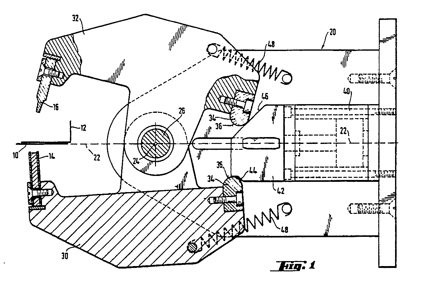
Description
Die Erfindung betrifft einen kraftbetriebenen zangenartigen Werkzeugträger für Handhabungsgeräte.The invention relates to a power-operated pliers-like tool holder for handling devices.
Unter einem Handhabungsgerät, landläufig "Roboter", soll ein Gerät verstanden werden, das programmgesteuert Bewegungen in Richtung mehrerer Freiheitsgrade ausführen kann. Ein bekanntes Beispiel sind Schweißautomaten, die an vorgegebenen Stellen von Kraftfahrzeugkarossen Punktschweißungen setzen. Dabei wird die Karosse oder, allgemeiner, das Werkstück in einer vorbestimmten Position abgestützt, wodurch ein räumliches Bezugs-Koordinatensystem gegeben ist, gemäß dem der Automat programmiert wird. Beim Schweißen üben beide Elektroden gleiche, entgegengesetzt gerichtete Kräfte auf das Werkstück aus, so daß dieses nicht deformiert, etwa durch eine Biegebelastung, wird.A handling device, commonly referred to as a “robot”, is to be understood as a device that can execute program-controlled movements in the direction of several degrees of freedom. A well-known example are automatic welding machines which place spot welds at predetermined positions on motor vehicle bodies. The body or, more generally, the workpiece is supported in a predetermined position, which provides a spatial reference coordinate system according to which the machine is programmed. When welding, both electrodes exert the same, oppositely directed forces on the workpiece so that it is not deformed, for example by a bending load.
Aufgabe der Erfindung ist es, einen Werkzeugträger für derartige Handhabungsgeräte für die Ausführung von Arbeitsgängen zu schaffen, bei denen einseitig wirkende Kräfte auftreten können.The object of the invention is to provide a tool carrier for handling devices of this type for carrying out work processes in which forces acting on one side can occur.
Diese Aufgabe wird durch die im Patentanspruch 1 angegebenen Merkmale gelöst. Der Nockenbahnkopf bestimmt dabei durch den Verlauf der jeweiligen Nockenbahnen den Bewegungsablauf der einzelnen (mindestens zwei) Zangenglieder, wobei jedoch nur ein einziger Antrieb vorgesehen zu sein braucht.This object is achieved by the features specified in claim 1. The cam track head determines the course of movement of the individual (at least two) pliers links through the course of the respective cam tracks, but only a single drive needs to be provided.
Die Unteransprüche definieren zweckmäßige Weiterbildungen des in Patentanspruch 1 zusammengefaßten Konzepts.The sub-claims define expedient developments of the concept summarized in claim 1.
Ein Ausführungsbeispiel des Gegenstandes der Erfindung ist in den beigefügten Zeichnungen weitgehend schematisiert dargestellt.An embodiment of the object of the invention is shown largely schematically in the accompanying drawings.
Die Figuren 1 bis 3 zeigen in teilgeschnittener Seitenansicht einen Werkzeugträger gemäß der Erfindung in drei aufeinanderfolgenden Etappen des Bewegungsablaufs.Figures 1 to 3 show a partially sectioned side view of a tool carrier according to the invention in three successive stages of the movement sequence.
Als Beispiel wird angenommen, daß ein Blechteil 10 mit einem Blechwinkel 12 mittels Durchsetzfügung verbunden werden soll; die hierfür verwendeten Werkzeuge sind im einzelnen in der Europäischen Patentschrift 77 932 beschrieben. Es genügt daher die nachfolgende Kurzbeschreibung:As an example, it is assumed that a
Die zu verbindenden Bleche werden auf einer Matrize 14 abgestützt, während ein Stempel von der andern Seite her die Bleche einschneidet und in den Matrizenhohlraum durchsetzt, wonach das durchgesetzte Material seitlich gebreitet wird; danach wird der Stempel 16 wieder zurückgezogen, und die Matrize wird vom Werkstück gelöst.The sheets to be connected are supported on a
Der Werkzeugträger umfaßt einen Sockel 20, der an einem Arbeitsarm (nicht gezeigt) eines Handhabungsgeräts in vorgegebener Position befestigt werden kann, z.B. durch Verschrauben. Damit ist die Lage des Sockels relativ zu den Arbeitsachsen des Handhabungsgeräts festgelegt. Es sei angenommen, daß der Arbeitsarm in Richtung einer Achse 22 verlagerbar sei und um diese Achse schwenken kann. Bei der Programmierung wird davon ausgegangen, daß die Unterseite des Blechs 10 die Bezugsebene ist, in der die Achse 22 liegen soll, und daß der Sockel 20 um die Achse 22 so gedreht wird, daß die Achse 24 des Gelenks 26 parallel zu dieser Bezugsebene verläuft. Wenn, wie hier vorgesehen, die Achse 22 die Gelenkachse 24 senkrecht schneidet, wird die Programmierung vereinfacht.The tool carrier comprises a
Abweichend von der vorgestellten Konstruktion können aber auch mehrere Gelenke vorgesehen sein, die vorzugsweise zueinander parallele Achsen aufweisen.Deviating from the construction presented, several joints can also be provided, which preferably have axes that are parallel to one another.
Um die Achse 24 schwenkbar sind zwei Zangenglieder 30 und 32, von denen das Zangenglied 30 die Matrize 14 und das Zangenglied 32 den Stempel 16 trägt. Die Zangenglieder sind als zweiarmige Hebel ausgeführt. Das den Werkzeugen -- Matrize bzw. Stempel -- abgewandte freie Ende ist jeweils mit einem Nockenfolger 34 bestückt, dessen Eingriffsfläche 36 abgerundet ist.Two
Am Sockel ist ein Arbeitszylinder, vorzugsweise ein Hydraulikzylinder 40 montiert, dessen Kolben einen Nockenbahnkopf 42 trägt. Der Nokkenbahnkopf ist auswechselbar zur Anpassung an unterschiedliche, an den Zangengliedern montierbare Werkzeuge. Der Nockenbahnkopf weist Nockenbahnen 44, 46 auf, jeweils eine für jedes Zangenglied, dessen Nockenfolger an der zugeordneten Nockenbahn mittels einer Vorspannfeder 48 in Anlage gehalten wird.A working cylinder, preferably a
In der Ausgangsposition nach Fig. 1 ist der Werkzeugträger in seiner Offenstellung, so daß er längs der Achse 22 über den Blechwinkel 12 in Arbeitsposition verfahren werden kann. Wird dann der Arbeitszylinder 40 betätigt, so wird zunächst das Zangenglied 30 durch die Nockenbahn 44 in seine Endlage verschwenkt, in der die Matrize gerade an der ihr zugekehrten Seite des Blechs 10 zur Anlage kommt. Zugleich wird der Stempel stetig dem Blechwinkel 12 genähert. Bei weiterem Hub des Arbeitskolbens bleibt das Zangenglied 30 stehen (der entsprechende Abschnitt der Nockenbahn 44 verläuft parallel zur Bezugs/ebene), während die Nockenbahn 46 den Stempel 16 in die in Fig. 3 dargestellte Position verschwenkt, in der der Fügevorgang beendet ist. Beim Rückhub des Arbeitskolbens verlaufen die Bewegungen der Zangenglieder in umgekehrter Reihenfolge.In the starting position according to FIG. 1, the tool carrier is in its open position, so that it can be moved along the
Es versteht sich, daß nicht nur -- wie im Ausführungsbeispiel -- zwei, sondern noch mehr Zangenglieder simultan betätigt werden können. So könnte beispielsweise ein weiteres Zangenglied ein Auswerferelement aufweisen, das das Werkstück aus der Matrize löst. Ferner könnte man auf die Vorspannfedern verzichten, wenn die Nockenfolger in kanalartigen Nockenbahnen zwangsgeführt würden.It goes without saying that not only - as in the exemplary embodiment - two, but even more pliers links can be actuated simultaneously. For example, another pliers member could have an ejector element that detaches the workpiece from the die. Furthermore, one could dispense with the bias springs if the cam followers were guided in channel-like cam tracks.
Claims (5)
einen in definierter Position mit dem Handhabungsgerät verbindbaren Sockel (20),
am Sockel angelenkte Zangenglieder (30, 32) in Form zweiarmiger Hebel, an deren Arbeitsende Werkzeuge (14, 16) befestigbar sind und an deren Antriebsende Nockenfolger (34) angeordnet sind,
einen am Sockel montierten Arbeitszylinder (40) zum Verlagern eines Nockenbahnkopfes (42) im wesentlichen senkrecht zu der Anlenkachse (24), welcher Nockenbahnkopf für jedes Zangenglied eine eigene Nockenbahn (44, 46) aufweist, an der der zugeordnete Nockenfolger anliegt.1. Power operated plier-like tool carrier for handling devices, comprising:
a base (20) which can be connected to the handling device in a defined position,
pliers links (30, 32) articulated on the base in the form of two-armed levers, tools (14, 16) can be attached to the working end thereof and cam followers (34) are arranged at the drive end,
a working cylinder (40) mounted on the base for displacing a cam track head (42) substantially perpendicular to the articulation axis (24), which cam track head has a separate cam track (44, 46) for each tong member, against which the assigned cam follower bears.
Applications Claiming Priority (2)
| Application Number | Priority Date | Filing Date | Title |
|---|---|---|---|
| DE3905466 | 1989-02-22 | ||
| DE3905466A DE3905466A1 (en) | 1989-02-22 | 1989-02-22 | POWERED PLIERS-LIKE TOOL HOLDER FOR HANDLING DEVICES |
Publications (3)
| Publication Number | Publication Date |
|---|---|
| EP0384100A2 true EP0384100A2 (en) | 1990-08-29 |
| EP0384100A3 EP0384100A3 (en) | 1991-05-29 |
| EP0384100B1 EP0384100B1 (en) | 1993-08-11 |
Family
ID=6374678
Family Applications (1)
| Application Number | Title | Priority Date | Filing Date |
|---|---|---|---|
| EP90100068A Expired - Lifetime EP0384100B1 (en) | 1989-02-22 | 1990-01-03 | Power driven pliers-type tool holder for handling devices |
Country Status (9)
| Country | Link |
|---|---|
| US (1) | US5040278A (en) |
| EP (1) | EP0384100B1 (en) |
| JP (1) | JPH02243287A (en) |
| AT (1) | ATE92802T1 (en) |
| CA (1) | CA2008433C (en) |
| DE (2) | DE3905466A1 (en) |
| DK (1) | DK0384100T3 (en) |
| ES (1) | ES2044233T3 (en) |
| SU (1) | SU1766242A3 (en) |
Cited By (1)
| Publication number | Priority date | Publication date | Assignee | Title |
|---|---|---|---|---|
| EP2508275A1 (en) * | 2011-04-04 | 2012-10-10 | Novopress GmbH Pressen und Presswerkzeuge & Co. KG | Press tool and pressed press fitting |
Families Citing this family (21)
| Publication number | Priority date | Publication date | Assignee | Title |
|---|---|---|---|---|
| US5077870A (en) | 1990-09-21 | 1992-01-07 | Minnesota Mining And Manufacturing Company | Mushroom-type hook strip for a mechanical fastener |
| US5337470A (en) * | 1993-03-03 | 1994-08-16 | Bethlehem Steel Corporation | Method and apparatus for removing a nozzle insert from a steelmaking ladle |
| US5404641A (en) * | 1993-08-16 | 1995-04-11 | Avco Corporation | Method of drilling through contiguous plate members using a robotic drill clamp |
| US5621958A (en) * | 1995-01-31 | 1997-04-22 | Woodcox; Gordon G. | Brake element processing device and method |
| US6115898A (en) * | 1995-06-06 | 2000-09-12 | Btm Corporation | Force multiplying apparatus for clamping a workpiece and forming a joint therein |
| GB2315236B (en) * | 1996-07-12 | 1999-04-07 | Standard Prod Ltd | Clinching apparatus |
| US5853211A (en) * | 1997-01-10 | 1998-12-29 | Btm Corporation | Universal gripper |
| US6132660A (en) * | 1997-06-19 | 2000-10-17 | 3M Innovative Properties Company | Method for forming headed stem mechanical fasteners |
| US5868987A (en) * | 1997-06-19 | 1999-02-09 | Minnesotamining And Manufacturing | Superimposed embossing of capped stem mechanical fastener structures |
| US6125684A (en) * | 1997-12-18 | 2000-10-03 | Phd, Inc. | Parts stamper |
| US6324886B1 (en) | 1997-12-18 | 2001-12-04 | Phd, Inc. | Parts stamper |
| US6233803B1 (en) * | 2000-02-25 | 2001-05-22 | Vought Aircraft Industries, Inc. | Angled C-squeezer attachment |
| US6405421B1 (en) * | 2001-01-03 | 2002-06-18 | Hon Hai Precisionind. Co., Ltd. | Die assembly for riveting |
| FR2865952B1 (en) * | 2004-02-10 | 2006-06-23 | Airbus France | METHOD AND DEVICE FOR THE MECHANICAL MACHINING OF FLEXIBLE PANELS, PARTICULARLY OF COMPLEX SHAPE |
| US20080016939A1 (en) * | 2004-07-02 | 2008-01-24 | Egbert Frenken | Pair of pressing jaws for hydraulic or electric pressing tools |
| US7216523B2 (en) * | 2004-07-02 | 2007-05-15 | Gustav Klauke Gmbh | Pair of pressing jaws for hydraulic or electric pressing tools, and insulating covering for a pressing jaw |
| DE202006013693U1 (en) * | 2006-09-07 | 2008-01-17 | Gustav Klauke Gmbh | Pressing jaw pair for hydraulic or electrical pressing devices |
| US7464578B2 (en) * | 2005-06-03 | 2008-12-16 | Fci Americas Technology, Inc. | Hand-held, portable, battery-powered hydraulic tool |
| US7290431B1 (en) | 2007-01-12 | 2007-11-06 | U.S. Industrial Tool & Supply Company | Rivet squeezer |
| DE102009049616B4 (en) * | 2009-10-16 | 2019-05-09 | Böllhoff Verbindungstechnik GmbH | Setting tool, feeding module of the setting device and joining method for connecting at least two components |
| CN109625929B (en) * | 2018-12-10 | 2024-05-03 | 苏州市天烨医疗设备有限公司 | Water mould autoloader |
Family Cites Families (10)
| Publication number | Priority date | Publication date | Assignee | Title |
|---|---|---|---|---|
| US1346022A (en) * | 1919-11-23 | 1920-07-06 | William G Hassel | Fuse remover and placer |
| US2405779A (en) * | 1944-05-17 | 1946-08-13 | Davis Jack | Tool for installing nut plates or the like |
| US3630391A (en) * | 1969-01-28 | 1971-12-28 | Gulf & Western Ind Prod Co | Work gripper |
| US3579795A (en) * | 1969-08-08 | 1971-05-25 | Burroughs Corp | Component removing tool |
| JPS5422458B2 (en) * | 1974-02-19 | 1979-08-07 | ||
| EP0077932B1 (en) * | 1981-10-28 | 1984-12-27 | WALTER ECKOLD GmbH & Co. KG Vorrichtungs- und Gerätebau | Apparatus for making a riveted joint of metal sheets |
| JPS60155390A (en) * | 1984-01-24 | 1985-08-15 | 三菱電機株式会社 | Hand device for industrial robot |
| US4571975A (en) * | 1984-03-29 | 1986-02-25 | Pawloski James A | Fluid actuated tool |
| US4599037A (en) * | 1984-07-02 | 1986-07-08 | United Technologies Corporation | Method and apparatus for manipulating miniature parts |
| AT391827B (en) * | 1984-12-07 | 1990-12-10 | Sticht Walter | HANDLING DEVICE FOR ASSEMBLY PARTS |
-
1989
- 1989-02-22 DE DE3905466A patent/DE3905466A1/en not_active Withdrawn
-
1990
- 1990-01-03 DK DK90100068.7T patent/DK0384100T3/en active
- 1990-01-03 EP EP90100068A patent/EP0384100B1/en not_active Expired - Lifetime
- 1990-01-03 ES ES90100068T patent/ES2044233T3/en not_active Expired - Lifetime
- 1990-01-03 DE DE9090100068T patent/DE59002234D1/en not_active Expired - Fee Related
- 1990-01-03 AT AT90100068T patent/ATE92802T1/en not_active IP Right Cessation
- 1990-01-24 CA CA002008433A patent/CA2008433C/en not_active Expired - Fee Related
- 1990-02-15 JP JP2035050A patent/JPH02243287A/en active Pending
- 1990-02-21 SU SU904743194A patent/SU1766242A3/en active
-
1991
- 1991-02-01 US US07/650,976 patent/US5040278A/en not_active Expired - Fee Related
Cited By (1)
| Publication number | Priority date | Publication date | Assignee | Title |
|---|---|---|---|---|
| EP2508275A1 (en) * | 2011-04-04 | 2012-10-10 | Novopress GmbH Pressen und Presswerkzeuge & Co. KG | Press tool and pressed press fitting |
Also Published As
| Publication number | Publication date |
|---|---|
| DE3905466A1 (en) | 1990-08-23 |
| EP0384100B1 (en) | 1993-08-11 |
| ES2044233T3 (en) | 1994-01-01 |
| CA2008433A1 (en) | 1990-08-22 |
| US5040278A (en) | 1991-08-20 |
| CA2008433C (en) | 1995-01-17 |
| ATE92802T1 (en) | 1993-08-15 |
| EP0384100A3 (en) | 1991-05-29 |
| DK0384100T3 (en) | 1993-10-25 |
| DE59002234D1 (en) | 1993-09-23 |
| SU1766242A3 (en) | 1992-09-30 |
| JPH02243287A (en) | 1990-09-27 |
Similar Documents
| Publication | Publication Date | Title |
|---|---|---|
| EP0384100B1 (en) | Power driven pliers-type tool holder for handling devices | |
| DE69001202T2 (en) | TOOLING SYSTEM FOR RIVETING WORKPIECES. | |
| DE3610317C2 (en) | ||
| DE2839978C2 (en) | ||
| DE69632478T2 (en) | PUNCHING PRESS AND PUNCHING PROCESS | |
| DE4020804C2 (en) | Device and method for welding connecting components to a pipe | |
| DE68904261T2 (en) | INDUSTRIAL ROBOTS FOR A PRESS SYSTEM, PRESS ARRANGEMENT AND METHOD FOR SHEETS. | |
| EP3191254B1 (en) | Laser ablation and welding method for workpieces | |
| DE3715927C2 (en) | ||
| DE10052509C1 (en) | Device for spot welding at least two components | |
| DE3506314A1 (en) | METHOD AND DEVICE FOR AUTOMATIC JOINTING AND EDITING | |
| DE3120772A1 (en) | WELDING DEVICE FOR A MOTOR VEHICLE BODY | |
| DE19905527A1 (en) | Ductile workpiece joining device, with reaction part of joining tool fixed to linearly movable part of holding-down device | |
| CH650424A5 (en) | FORGING MACHINE WITH AUTOMATIC TOOL CHANGE. | |
| EP0638010B1 (en) | Method and device for the automatic assembly and working of several components | |
| DE102016009520A1 (en) | Processing system with machine tool and robot for attaching and detaching a workpiece | |
| DE102020133999B4 (en) | Resetting device and method for resetting a plate-shaped workpiece in a processing machine | |
| AT397625B (en) | MANIPULATOR FOR A BENDING MACHINE AND ROBOT EQUIPPED WITH THIS MANIPULATOR | |
| EP4380738B1 (en) | Device for clinch joining | |
| DE3916014C2 (en) | ||
| DE3428992C1 (en) | Apparatus for the automatic loading of several work stations or machine tools with workpieces | |
| EP3381581B1 (en) | Punch rivet device and method for operating the same | |
| DE60112648T2 (en) | Method for cutting parts out of a metal sheet | |
| DE3431974C2 (en) | ||
| DE4125946A1 (en) | METHOD FOR ASSEMBLING CONSTRUCTIONS, ESPECIALLY AVIATION TECHNICAL CONSTRUCTIONS |
Legal Events
| Date | Code | Title | Description |
|---|---|---|---|
| PUAI | Public reference made under article 153(3) epc to a published international application that has entered the european phase |
Free format text: ORIGINAL CODE: 0009012 |
|
| AK | Designated contracting states |
Kind code of ref document: A2 Designated state(s): AT BE CH DE DK ES FR GB GR IT LI LU NL SE |
|
| PUAL | Search report despatched |
Free format text: ORIGINAL CODE: 0009013 |
|
| AK | Designated contracting states |
Kind code of ref document: A3 Designated state(s): AT BE CH DE DK ES FR GB GR IT LI LU NL SE |
|
| 17P | Request for examination filed |
Effective date: 19911127 |
|
| 17Q | First examination report despatched |
Effective date: 19920709 |
|
| GRAA | (expected) grant |
Free format text: ORIGINAL CODE: 0009210 |
|
| AK | Designated contracting states |
Kind code of ref document: B1 Designated state(s): AT BE CH DE DK ES FR GB GR IT LI LU NL SE |
|
| PG25 | Lapsed in a contracting state [announced via postgrant information from national office to epo] |
Ref country code: GR Free format text: LAPSE BECAUSE OF FAILURE TO SUBMIT A TRANSLATION OF THE DESCRIPTION OR TO PAY THE FEE WITHIN THE PRESCRIBED TIME-LIMIT Effective date: 19930811 |
|
| REF | Corresponds to: |
Ref document number: 92802 Country of ref document: AT Date of ref document: 19930815 Kind code of ref document: T |
|
| REF | Corresponds to: |
Ref document number: 59002234 Country of ref document: DE Date of ref document: 19930923 |
|
| ITF | It: translation for a ep patent filed | ||
| REG | Reference to a national code |
Ref country code: DK Ref legal event code: T3 |
|
| ET | Fr: translation filed | ||
| GBT | Gb: translation of ep patent filed (gb section 77(6)(a)/1977) |
Effective date: 19931118 |
|
| REG | Reference to a national code |
Ref country code: ES Ref legal event code: FG2A Ref document number: 2044233 Country of ref document: ES Kind code of ref document: T3 |
|
| PG25 | Lapsed in a contracting state [announced via postgrant information from national office to epo] |
Ref country code: LU Free format text: LAPSE BECAUSE OF NON-PAYMENT OF DUE FEES Effective date: 19940131 |
|
| PLBE | No opposition filed within time limit |
Free format text: ORIGINAL CODE: 0009261 |
|
| STAA | Information on the status of an ep patent application or granted ep patent |
Free format text: STATUS: NO OPPOSITION FILED WITHIN TIME LIMIT |
|
| 26N | No opposition filed | ||
| EAL | Se: european patent in force in sweden |
Ref document number: 90100068.7 |
|
| PGFP | Annual fee paid to national office [announced via postgrant information from national office to epo] |
Ref country code: GB Payment date: 19971211 Year of fee payment: 9 |
|
| PGFP | Annual fee paid to national office [announced via postgrant information from national office to epo] |
Ref country code: SE Payment date: 19971217 Year of fee payment: 9 |
|
| PGFP | Annual fee paid to national office [announced via postgrant information from national office to epo] |
Ref country code: AT Payment date: 19971223 Year of fee payment: 9 |
|
| PGFP | Annual fee paid to national office [announced via postgrant information from national office to epo] |
Ref country code: DK Payment date: 19971230 Year of fee payment: 9 |
|
| PGFP | Annual fee paid to national office [announced via postgrant information from national office to epo] |
Ref country code: FR Payment date: 19971231 Year of fee payment: 9 |
|
| PGFP | Annual fee paid to national office [announced via postgrant information from national office to epo] |
Ref country code: CH Payment date: 19980107 Year of fee payment: 9 |
|
| PGFP | Annual fee paid to national office [announced via postgrant information from national office to epo] |
Ref country code: BE Payment date: 19980108 Year of fee payment: 9 |
|
| PGFP | Annual fee paid to national office [announced via postgrant information from national office to epo] |
Ref country code: ES Payment date: 19980119 Year of fee payment: 9 |
|
| PGFP | Annual fee paid to national office [announced via postgrant information from national office to epo] |
Ref country code: NL Payment date: 19980130 Year of fee payment: 9 |
|
| PGFP | Annual fee paid to national office [announced via postgrant information from national office to epo] |
Ref country code: DE Payment date: 19980318 Year of fee payment: 9 |
|
| PG25 | Lapsed in a contracting state [announced via postgrant information from national office to epo] |
Ref country code: GB Free format text: LAPSE BECAUSE OF NON-PAYMENT OF DUE FEES Effective date: 19990103 Ref country code: AT Free format text: LAPSE BECAUSE OF NON-PAYMENT OF DUE FEES Effective date: 19990103 |
|
| PG25 | Lapsed in a contracting state [announced via postgrant information from national office to epo] |
Ref country code: SE Free format text: LAPSE BECAUSE OF NON-PAYMENT OF DUE FEES Effective date: 19990104 Ref country code: ES Free format text: LAPSE BECAUSE OF EXPIRATION OF PROTECTION Effective date: 19990104 |
|
| PG25 | Lapsed in a contracting state [announced via postgrant information from national office to epo] |
Ref country code: LI Free format text: LAPSE BECAUSE OF NON-PAYMENT OF DUE FEES Effective date: 19990131 Ref country code: CH Free format text: LAPSE BECAUSE OF NON-PAYMENT OF DUE FEES Effective date: 19990131 Ref country code: BE Free format text: LAPSE BECAUSE OF NON-PAYMENT OF DUE FEES Effective date: 19990131 |
|
| PG25 | Lapsed in a contracting state [announced via postgrant information from national office to epo] |
Ref country code: DK Free format text: LAPSE BECAUSE OF NON-PAYMENT OF DUE FEES Effective date: 19990202 |
|
| BERE | Be: lapsed |
Owner name: MAASS HANS Effective date: 19990131 Owner name: ECKOLD GERD-JURGEN Effective date: 19990131 |
|
| PG25 | Lapsed in a contracting state [announced via postgrant information from national office to epo] |
Ref country code: NL Free format text: LAPSE BECAUSE OF NON-PAYMENT OF DUE FEES Effective date: 19990801 |
|
| GBPC | Gb: european patent ceased through non-payment of renewal fee |
Effective date: 19990103 |
|
| REG | Reference to a national code |
Ref country code: CH Ref legal event code: PL |
|
| PG25 | Lapsed in a contracting state [announced via postgrant information from national office to epo] |
Ref country code: FR Free format text: LAPSE BECAUSE OF NON-PAYMENT OF DUE FEES Effective date: 19990930 |
|
| PG25 | Lapsed in a contracting state [announced via postgrant information from national office to epo] |
Ref country code: DE Free format text: LAPSE BECAUSE OF NON-PAYMENT OF DUE FEES Effective date: 19991103 |
|
| REG | Reference to a national code |
Ref country code: FR Ref legal event code: ST |
|
| REG | Reference to a national code |
Ref country code: DK Ref legal event code: EBP |
|
| REG | Reference to a national code |
Ref country code: ES Ref legal event code: FD2A Effective date: 20010910 |
|
| PG25 | Lapsed in a contracting state [announced via postgrant information from national office to epo] |
Ref country code: IT Free format text: LAPSE BECAUSE OF NON-PAYMENT OF DUE FEES;WARNING: LAPSES OF ITALIAN PATENTS WITH EFFECTIVE DATE BEFORE 2007 MAY HAVE OCCURRED AT ANY TIME BEFORE 2007. THE CORRECT EFFECTIVE DATE MAY BE DIFFERENT FROM THE ONE RECORDED. Effective date: 20050103 |