EP0384149A1 - Vorrichtung zur Erzeugung unterschiedlicher Drehzahlen für eine Waschmaschine - Google Patents
Vorrichtung zur Erzeugung unterschiedlicher Drehzahlen für eine Waschmaschine Download PDFInfo
- Publication number
- EP0384149A1 EP0384149A1 EP90101525A EP90101525A EP0384149A1 EP 0384149 A1 EP0384149 A1 EP 0384149A1 EP 90101525 A EP90101525 A EP 90101525A EP 90101525 A EP90101525 A EP 90101525A EP 0384149 A1 EP0384149 A1 EP 0384149A1
- Authority
- EP
- European Patent Office
- Prior art keywords
- speed variator
- drum
- flyweight
- speed
- flyweights
- Prior art date
- Legal status (The legal status is an assumption and is not a legal conclusion. Google has not performed a legal analysis and makes no representation as to the accuracy of the status listed.)
- Granted
Links
- 238000010412 laundry washing Methods 0.000 title claims abstract description 9
- 230000005540 biological transmission Effects 0.000 claims abstract description 9
- 238000001035 drying Methods 0.000 claims abstract description 8
- 238000004900 laundering Methods 0.000 claims abstract description 7
- 239000000463 material Substances 0.000 claims abstract description 4
- 239000013536 elastomeric material Substances 0.000 claims 1
- 238000006073 displacement reaction Methods 0.000 description 5
- 230000004308 accommodation Effects 0.000 description 3
- 238000010276 construction Methods 0.000 description 1
- 239000013013 elastic material Substances 0.000 description 1
- 230000008030 elimination Effects 0.000 description 1
- 238000003379 elimination reaction Methods 0.000 description 1
- 238000010348 incorporation Methods 0.000 description 1
- 239000002184 metal Substances 0.000 description 1
Images

Classifications
-
- D—TEXTILES; PAPER
- D06—TREATMENT OF TEXTILES OR THE LIKE; LAUNDERING; FLEXIBLE MATERIALS NOT OTHERWISE PROVIDED FOR
- D06F—LAUNDERING, DRYING, IRONING, PRESSING OR FOLDING TEXTILE ARTICLES
- D06F37/00—Details specific to washing machines covered by groups D06F21/00 - D06F25/00
- D06F37/30—Driving arrangements
- D06F37/36—Driving arrangements for rotating the receptacle at more than one speed
Definitions
- the present invention relates to a speed variator for a laundry washing machine, which is configured to ensure its silent and reliable operation.
- Conventional laundry washing machines are equipped with a speed variator operable to rotate the drum of the respective machine at variable transmission ratios and substantially comprising a variable-diameter driving pulley fixedly mounted on the output shaft of the electric motor of the machine and connected by a transmission V-belt to a corresponding driven pulley fixedly mounted on the shaft of the drum, said driving pulley being provided with radially displaceable flyweights dimensioned and designed to be directly displaceable from radially contracted first position corresponding to the laundering speed of the drum, to a radially expanded second position corresponding to the maximum spin-drying speed of the machine, and back again to the first position.
- a speed variator of this type is obtained by the incorporation therein of the structural characteristics described with particular reference to the claims of the present application.
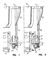
- a speed variator 5 for a laundry washing machine operable to control the rotation of the drum 6 of the machine at variable transmission ratios, and comprising a driving pulley 7 adapted to be rotated by an electric motor 8 of the machine and connected by a transmission V-belt 9 to a driven pulley 10 fixedly secured to the rotatable shaft 11 of drum 6.
- driving pulley 7 is composed of a disc 12 fixedly mounted on the output shaft 13 of motor 8, a disc 14 mounted for axial displacement on shaft 13 relative to disc 12, and a further disc 15 secured to the end of output shaft 13, discs 12 and 14 cooperating to form a V-shaped groove 16 for the accommodation therein of V-belt 9.
- Discs 14 and 15 on their part cooperate to define at least one internal cavity 17 therebetween, formed with seats 18 for the accommodation therein of a corresponding number of radially displaceable flyweights 19 of preferably cylindrical shape (cf. also fig. 3).
- motor 8 thus results in the rotation of driving pulley 7 in unison with flyweights 19.
- Motor 8 is advantageously designed to rotate drum 6 at two different speeds, specifically at a lower laundering speed and a higher spin-drying speed; the motor may also be designed, however, to operate at a greater number of different speeds.
- Flyweights 19 on their part are dimensioned and designed to radially expand in response to the operation of motor 8 at the spin-drying speed, to thereby cause movable disc 14 to be axially displaced towards fixed disc 12, with the consequent variation of the effective diameter of driving pulley 7.
- V-belt 9 is displaced between different diameters of driving pulley 9, specifically between a minimum diameter as shown in fig. 1 and a maximum effective diameter illustrated in fig. 2, corresponding respectively to the laundering speed and the spin-drying speed of motor 8, to thereby rotate drum 6 at different transmission ratios.
- each flyweight 19 is subdivided into at least two symmetrically identical metal components 20 and 21 adapted to be joined to one another by the interposition therebetween of at least one elastic element 22 made of rubber or a similarly elastic material capable of dampening mechanical loads (cf. figs. 3 and 4).
- Elastic element 22 is formed with a central flange 23 of circular shape and two cylindrical portions 24 and 25 projecting laterally from flange 23 and adapted to be inserted by the exertion thereon of a slight force into corresponding blind bores 26 and 27 formed respectively in the two components 20 and 21 of flyweight 19.
- Each cylindrical portion 24 and 25 is formed with a central recess 28 and 29, respectively, of preferably conical shape extending thereinto from the respective outer end face, and with a number of grooves or slots 30 and 31, respectively, extending over the full length of the outer surface of the respective portion.
- Conical recesses 28 and 29 serve the purpose of permitting the material of the cylindrical portion 24 and 25 of elastic element 22 to resiliently yield to mechanical loads, so that, thanks to the abutment of the central flange 23 of the elastic element on the respective end faces of the two components 20 and 21 of flyweight 19, the elastic element 22 is capable of effectively absorbing and dampening the mechanical loads transmitted axially through the flyweight during the operation of the speed variator.
- the axial grooves or slots 30 and 31 serve the purpose of permitting air to escape from the blind bores 26 and 27 of the two parts 20 and 21, respectively, of flyweight 19 when the cylindrical portions 24 and 25 of elastic element 22 are inserted thereinto during assembly of flyweight 19, to thereby establish a state of equilibrium between the air pressure within the respective blind bore and the outside air pressure,resulting in the correct posit ioning of the cylindrical portions in the respective blind bores during the operation of the laundry washing machine.
- the central flange 23 of the respective elastic element 22 is addionally capable of effectively absorbing and dampening mechanical loads acting on the flyweight in the radial direction, thanks to the elastic yielding of the material of the flange when coming into contact with the wall of the respective seat 18 formed in the speed variator for the accommodation of the respective flyweight.
Landscapes
- Engineering & Computer Science (AREA)
- Textile Engineering (AREA)
- Detail Structures Of Washing Machines And Dryers (AREA)
- Main Body Construction Of Washing Machines And Laundry Dryers (AREA)
- Apparatuses For Bulk Treatment Of Fruits And Vegetables And Apparatuses For Preparing Feeds (AREA)
- Connection Of Motors, Electrical Generators, Mechanical Devices, And The Like (AREA)
- Accessory Of Washing/Drying Machine, Commercial Washing/Drying Machine, Other Washing/Drying Machine (AREA)
- Centrifugal Separators (AREA)
- Detergent Compositions (AREA)
Priority Applications (1)
| Application Number | Priority Date | Filing Date | Title |
|---|---|---|---|
| AT90101525T ATE93906T1 (de) | 1989-02-23 | 1990-01-25 | Vorrichtung zur erzeugung unterschiedlicher drehzahlen fuer eine waschmaschine. |
Applications Claiming Priority (2)
| Application Number | Priority Date | Filing Date | Title |
|---|---|---|---|
| IT8945712A IT1234687B (it) | 1989-02-23 | 1989-02-23 | Variatore di velocita' per macchine lavabiancheria. |
| IT4571289 | 1989-02-23 |
Publications (2)
| Publication Number | Publication Date |
|---|---|
| EP0384149A1 true EP0384149A1 (de) | 1990-08-29 |
| EP0384149B1 EP0384149B1 (de) | 1993-09-01 |
Family
ID=11257536
Family Applications (1)
| Application Number | Title | Priority Date | Filing Date |
|---|---|---|---|
| EP90101525A Expired - Lifetime EP0384149B1 (de) | 1989-02-23 | 1990-01-25 | Vorrichtung zur Erzeugung unterschiedlicher Drehzahlen für eine Waschmaschine |
Country Status (5)
| Country | Link |
|---|---|
| EP (1) | EP0384149B1 (de) |
| AT (1) | ATE93906T1 (de) |
| DE (1) | DE69002961T2 (de) |
| ES (1) | ES2054112T3 (de) |
| IT (1) | IT1234687B (de) |
Cited By (3)
| Publication number | Priority date | Publication date | Assignee | Title |
|---|---|---|---|---|
| WO2017025010A1 (zh) * | 2015-08-07 | 2017-02-16 | 青岛海尔洗衣机有限公司 | 洗衣机 |
| WO2017036371A1 (zh) * | 2015-08-28 | 2017-03-09 | 青岛海尔洗衣机有限公司 | 洗衣机 |
| KR20180033298A (ko) * | 2015-08-17 | 2018-04-02 | 칭다오 하이어 워싱 머신 캄파니 리미티드 | 세탁기 |
Citations (3)
| Publication number | Priority date | Publication date | Assignee | Title |
|---|---|---|---|---|
| GB2129072A (en) * | 1982-10-27 | 1984-05-10 | Riccardo Bertolino | Expanding pulley |
| US4496335A (en) * | 1982-12-13 | 1985-01-29 | Dayco Corporation | Pulley construction and method of making the same |
| EP0175218A2 (de) * | 1984-09-18 | 1986-03-26 | INDUSTRIE ZANUSSI S.p.A. | Wechselgetriebe für Waschmaschine |
-
1989
- 1989-02-23 IT IT8945712A patent/IT1234687B/it active
-
1990
- 1990-01-25 EP EP90101525A patent/EP0384149B1/de not_active Expired - Lifetime
- 1990-01-25 ES ES90101525T patent/ES2054112T3/es not_active Expired - Lifetime
- 1990-01-25 DE DE90101525T patent/DE69002961T2/de not_active Expired - Fee Related
- 1990-01-25 AT AT90101525T patent/ATE93906T1/de not_active IP Right Cessation
Patent Citations (3)
| Publication number | Priority date | Publication date | Assignee | Title |
|---|---|---|---|---|
| GB2129072A (en) * | 1982-10-27 | 1984-05-10 | Riccardo Bertolino | Expanding pulley |
| US4496335A (en) * | 1982-12-13 | 1985-01-29 | Dayco Corporation | Pulley construction and method of making the same |
| EP0175218A2 (de) * | 1984-09-18 | 1986-03-26 | INDUSTRIE ZANUSSI S.p.A. | Wechselgetriebe für Waschmaschine |
Cited By (12)
| Publication number | Priority date | Publication date | Assignee | Title |
|---|---|---|---|---|
| WO2017025010A1 (zh) * | 2015-08-07 | 2017-02-16 | 青岛海尔洗衣机有限公司 | 洗衣机 |
| CN107849789A (zh) * | 2015-08-07 | 2018-03-27 | 青岛海尔洗衣机有限公司 | 洗衣机 |
| KR20180033299A (ko) * | 2015-08-07 | 2018-04-02 | 칭다오 하이어 워싱 머신 캄파니 리미티드 | 세탁기 |
| US20180216275A1 (en) * | 2015-08-07 | 2018-08-02 | Qingdao Haier Washing Machine Co., Ltd. | Washing machine |
| EP3333304A4 (de) * | 2015-08-07 | 2019-04-24 | Qingdao Haier Washing Machine Co., Ltd. | Waschmaschine |
| CN107849789B (zh) * | 2015-08-07 | 2020-06-23 | 青岛胶南海尔洗衣机有限公司 | 洗衣机 |
| KR20180033298A (ko) * | 2015-08-17 | 2018-04-02 | 칭다오 하이어 워싱 머신 캄파니 리미티드 | 세탁기 |
| CN107923110A (zh) * | 2015-08-17 | 2018-04-17 | 青岛海尔洗衣机有限公司 | 洗衣机 |
| CN107923110B (zh) * | 2015-08-17 | 2020-05-12 | 青岛海尔洗衣机有限公司 | 洗衣机 |
| WO2017036371A1 (zh) * | 2015-08-28 | 2017-03-09 | 青岛海尔洗衣机有限公司 | 洗衣机 |
| KR20180044392A (ko) * | 2015-08-28 | 2018-05-02 | 칭다오 하이어 워싱 머신 캄파니 리미티드 | 세탁기 |
| KR102032734B1 (ko) | 2015-08-28 | 2019-10-16 | 칭다오 하이어 워싱 머신 캄파니 리미티드 | 세탁기 |
Also Published As
| Publication number | Publication date |
|---|---|
| EP0384149B1 (de) | 1993-09-01 |
| ATE93906T1 (de) | 1993-09-15 |
| DE69002961T2 (de) | 1993-12-16 |
| DE69002961D1 (de) | 1993-10-07 |
| IT1234687B (it) | 1992-05-26 |
| ES2054112T3 (es) | 1994-08-01 |
| IT8945712A0 (it) | 1989-02-23 |
Similar Documents
| Publication | Publication Date | Title |
|---|---|---|
| KR100504867B1 (ko) | 인덕션모터를 구비한 드럼 세탁기 | |
| EP0384149B1 (de) | Vorrichtung zur Erzeugung unterschiedlicher Drehzahlen für eine Waschmaschine | |
| US3393572A (en) | Variable pulley | |
| US2718294A (en) | Automatic, centrifugal clutch mechanisms | |
| EP0147625B1 (de) | Wechselgetriebe für eine Waschmaschine | |
| KR20040094407A (ko) | 다중 시동장치-발전기 수단을 구비하는 클러치-바이-와이어 | |
| EP0993098A2 (de) | Vorrichtung zur Regelung eines Wechselstromgenerators für Fahrzeuge | |
| EP0285072A2 (de) | Treibriemen | |
| EP0175218B1 (de) | Wechselgetriebe für Waschmaschine | |
| US3459061A (en) | Variable diameter pulley construction | |
| JPS5842854A (ja) | ベルト式自動変速機 | |
| GB2137732A (en) | Speed equalizing couplings | |
| EP1662182B1 (de) | Stufenloses Getriebe für Motor-Fahrzeuge | |
| GB2129072A (en) | Expanding pulley | |
| US3088303A (en) | Automatic washing machine having a variable speed drive | |
| KR100276918B1 (ko) | 벨트무단변속장치 | |
| EP1087156A2 (de) | Stufenloses Getriebe mit Vorrichtung zur Einstellung der Axialkraft die auf die bewegliche Scheibenhälfte ausgeübt wird, als eine Funktion des übertragenen Drehmoments | |
| IT1270268B (it) | Variatore di velocita' con puleggia a diametro variabile | |
| SU889955A1 (ru) | Центробежна муфта | |
| SU1418365A1 (ru) | Центрифуга дл отжима текстильных изделий | |
| FR2432572A1 (fr) | Dispositif perfectionne pour la transmission du mouvement a une machine a laver le linge | |
| KR940021807A (ko) | 전자동 세탁기 | |
| JPH04219552A (ja) | 車載補機の駆動装置 | |
| SU1076669A1 (ru) | Бесступенчата передача | |
| KR100286609B1 (ko) | 자동차 밸트형무단변속기의 2웨이클러치 |
Legal Events
| Date | Code | Title | Description |
|---|---|---|---|
| PUAI | Public reference made under article 153(3) epc to a published international application that has entered the european phase |
Free format text: ORIGINAL CODE: 0009012 |
|
| AK | Designated contracting states |
Kind code of ref document: A1 Designated state(s): AT DE ES FR GB IT SE |
|
| 17P | Request for examination filed |
Effective date: 19910214 |
|
| 17Q | First examination report despatched |
Effective date: 19920708 |
|
| ITF | It: translation for a ep patent filed | ||
| GRAA | (expected) grant |
Free format text: ORIGINAL CODE: 0009210 |
|
| AK | Designated contracting states |
Kind code of ref document: B1 Designated state(s): AT DE ES FR GB IT SE |
|
| REF | Corresponds to: |
Ref document number: 93906 Country of ref document: AT Date of ref document: 19930915 Kind code of ref document: T |
|
| ET | Fr: translation filed | ||
| REF | Corresponds to: |
Ref document number: 69002961 Country of ref document: DE Date of ref document: 19931007 |
|
| PLBE | No opposition filed within time limit |
Free format text: ORIGINAL CODE: 0009261 |
|
| STAA | Information on the status of an ep patent application or granted ep patent |
Free format text: STATUS: NO OPPOSITION FILED WITHIN TIME LIMIT |
|
| REG | Reference to a national code |
Ref country code: ES Ref legal event code: FG2A Ref document number: 2054112 Country of ref document: ES Kind code of ref document: T3 |
|
| 26N | No opposition filed | ||
| EAL | Se: european patent in force in sweden |
Ref document number: 90101525.5 |
|
| REG | Reference to a national code |
Ref country code: GB Ref legal event code: IF02 |
|
| PGFP | Annual fee paid to national office [announced via postgrant information from national office to epo] |
Ref country code: AT Payment date: 20021205 Year of fee payment: 14 |
|
| PGFP | Annual fee paid to national office [announced via postgrant information from national office to epo] |
Ref country code: FR Payment date: 20021209 Year of fee payment: 14 |
|
| PGFP | Annual fee paid to national office [announced via postgrant information from national office to epo] |
Ref country code: GB Payment date: 20021212 Year of fee payment: 14 |
|
| PGFP | Annual fee paid to national office [announced via postgrant information from national office to epo] |
Ref country code: DE Payment date: 20021213 Year of fee payment: 14 |
|
| PGFP | Annual fee paid to national office [announced via postgrant information from national office to epo] |
Ref country code: SE Payment date: 20021230 Year of fee payment: 14 |
|
| PGFP | Annual fee paid to national office [announced via postgrant information from national office to epo] |
Ref country code: ES Payment date: 20030113 Year of fee payment: 14 |
|
| PG25 | Lapsed in a contracting state [announced via postgrant information from national office to epo] |
Ref country code: GB Free format text: LAPSE BECAUSE OF NON-PAYMENT OF DUE FEES Effective date: 20040125 Ref country code: AT Free format text: LAPSE BECAUSE OF NON-PAYMENT OF DUE FEES Effective date: 20040125 |
|
| PG25 | Lapsed in a contracting state [announced via postgrant information from national office to epo] |
Ref country code: SE Free format text: LAPSE BECAUSE OF NON-PAYMENT OF DUE FEES Effective date: 20040126 Ref country code: ES Free format text: LAPSE BECAUSE OF NON-PAYMENT OF DUE FEES Effective date: 20040126 |
|
| PG25 | Lapsed in a contracting state [announced via postgrant information from national office to epo] |
Ref country code: DE Free format text: LAPSE BECAUSE OF NON-PAYMENT OF DUE FEES Effective date: 20040803 |
|
| EUG | Se: european patent has lapsed | ||
| GBPC | Gb: european patent ceased through non-payment of renewal fee |
Effective date: 20040125 |
|
| PG25 | Lapsed in a contracting state [announced via postgrant information from national office to epo] |
Ref country code: FR Free format text: LAPSE BECAUSE OF NON-PAYMENT OF DUE FEES Effective date: 20040930 |
|
| REG | Reference to a national code |
Ref country code: FR Ref legal event code: ST |
|
| PG25 | Lapsed in a contracting state [announced via postgrant information from national office to epo] |
Ref country code: IT Free format text: LAPSE BECAUSE OF NON-PAYMENT OF DUE FEES;WARNING: LAPSES OF ITALIAN PATENTS WITH EFFECTIVE DATE BEFORE 2007 MAY HAVE OCCURRED AT ANY TIME BEFORE 2007. THE CORRECT EFFECTIVE DATE MAY BE DIFFERENT FROM THE ONE RECORDED. Effective date: 20050125 |
|
| REG | Reference to a national code |
Ref country code: ES Ref legal event code: FD2A Effective date: 20040126 |