EP0384706A1 - Aubes de redresseur à calage variable pour compresseur - Google Patents
Aubes de redresseur à calage variable pour compresseur Download PDFInfo
- Publication number
- EP0384706A1 EP0384706A1 EP90301806A EP90301806A EP0384706A1 EP 0384706 A1 EP0384706 A1 EP 0384706A1 EP 90301806 A EP90301806 A EP 90301806A EP 90301806 A EP90301806 A EP 90301806A EP 0384706 A1 EP0384706 A1 EP 0384706A1
- Authority
- EP
- European Patent Office
- Prior art keywords
- vane
- vanes
- fluid
- compressor
- button
- Prior art date
- Legal status (The legal status is an assumption and is not a legal conclusion. Google has not performed a legal analysis and makes no representation as to the accuracy of the status listed.)
- Granted
Links
- 239000012530 fluid Substances 0.000 claims abstract description 28
- 230000000452 restraining effect Effects 0.000 claims abstract description 6
- 238000010276 construction Methods 0.000 description 7
- 230000004044 response Effects 0.000 description 5
- 230000006872 improvement Effects 0.000 description 3
- 238000000034 method Methods 0.000 description 2
- 238000012986 modification Methods 0.000 description 2
- 230000004048 modification Effects 0.000 description 2
- 230000000712 assembly Effects 0.000 description 1
- 238000000429 assembly Methods 0.000 description 1
- 230000005284 excitation Effects 0.000 description 1
- 230000008520 organization Effects 0.000 description 1
Images

Classifications
-
- F—MECHANICAL ENGINEERING; LIGHTING; HEATING; WEAPONS; BLASTING
- F01—MACHINES OR ENGINES IN GENERAL; ENGINE PLANTS IN GENERAL; STEAM ENGINES
- F01D—NON-POSITIVE DISPLACEMENT MACHINES OR ENGINES, e.g. STEAM TURBINES
- F01D17/00—Regulating or controlling by varying flow
- F01D17/10—Final actuators
- F01D17/12—Final actuators arranged in stator parts
- F01D17/14—Final actuators arranged in stator parts varying effective cross-sectional area of nozzles or guide conduits
- F01D17/16—Final actuators arranged in stator parts varying effective cross-sectional area of nozzles or guide conduits by means of nozzle vanes
- F01D17/162—Final actuators arranged in stator parts varying effective cross-sectional area of nozzles or guide conduits by means of nozzle vanes for axial flow, i.e. the vanes turning around axes which are essentially perpendicular to the rotor centre line
-
- F—MECHANICAL ENGINEERING; LIGHTING; HEATING; WEAPONS; BLASTING
- F01—MACHINES OR ENGINES IN GENERAL; ENGINE PLANTS IN GENERAL; STEAM ENGINES
- F01D—NON-POSITIVE DISPLACEMENT MACHINES OR ENGINES, e.g. STEAM TURBINES
- F01D5/00—Blades; Blade-carrying members; Heating, heat-insulating, cooling or antivibration means on the blades or the members
- F01D5/12—Blades
- F01D5/26—Antivibration means not restricted to blade form or construction or to blade-to-blade connections or to the use of particular materials
-
- F—MECHANICAL ENGINEERING; LIGHTING; HEATING; WEAPONS; BLASTING
- F01—MACHINES OR ENGINES IN GENERAL; ENGINE PLANTS IN GENERAL; STEAM ENGINES
- F01D—NON-POSITIVE DISPLACEMENT MACHINES OR ENGINES, e.g. STEAM TURBINES
- F01D9/00—Stators
- F01D9/02—Nozzles; Nozzle boxes; Stator blades; Guide conduits, e.g. individual nozzles
- F01D9/04—Nozzles; Nozzle boxes; Stator blades; Guide conduits, e.g. individual nozzles forming ring or sector
- F01D9/042—Nozzles; Nozzle boxes; Stator blades; Guide conduits, e.g. individual nozzles forming ring or sector fixing blades to stators
-
- F—MECHANICAL ENGINEERING; LIGHTING; HEATING; WEAPONS; BLASTING
- F04—POSITIVE - DISPLACEMENT MACHINES FOR LIQUIDS; PUMPS FOR LIQUIDS OR ELASTIC FLUIDS
- F04D—NON-POSITIVE-DISPLACEMENT PUMPS
- F04D29/00—Details, component parts, or accessories
- F04D29/40—Casings; Connections of working fluid
- F04D29/52—Casings; Connections of working fluid for axial pumps
- F04D29/54—Fluid-guiding means, e.g. diffusers
- F04D29/56—Fluid-guiding means, e.g. diffusers adjustable
- F04D29/563—Fluid-guiding means, e.g. diffusers adjustable specially adapted for elastic fluid pumps
Definitions
- This invention relates generally to improvements to variable inlet guide vanes in compressors, such, for example, as axial flow compressors of the type used in industrial gas turbines. More particularly, the invention relates to improved constructions for reducing or suppressing vibratory response in variable inlet guide vanes which are caused by aerodynamic forces on the vanes at different rotated positions, particularly when the vanes are in the open position.
- Axial flow compressors used in industrial gas turbines often employ stationary radial vanes which may be rotated in unison to vary the angles of the vanes with respect to the fluid flowing through an annular passage in the frame of the compressor.
- the vanes are often rotatably mounted on radial spindles which support the outer part of the vanes.
- the inner tips of the vanes are subject to deflection and vibratory response, which varies with the turbulent conditions of fluid flow and with the position of the vanes.
- one object of the present invention is to provide an improved construction for suppressing or reducing vibratory response of variable inlet guide vanes in compressors, especially in an open position of the vanes when aerodynamic forces are at a minimum.
- an improved form of inner tip support for the variable inlet guide vanes in an axial flow compressor which includes a frame defining an annular path for axial fluid flow and a set of variable, radially extending, circumferentially spaced inlet guide vanes.
- Each of the guide vanes is rotatably mounted on a spindle at its radially outer end and has radially inner ends subject to deflection and vibration due to aerodynamic forces of the axial fluid flow.
- a bushing disposed in the frame radially inward of each of said guide vanes, and a button on the end of each of said guide vanes is contained within the forms close clearances with the bushing walls.
- the improvement comprises the mounting of the button so that it is eccentrically offset with resepct to the guide vane spindle by a preselected amount and in a preselected direction to cause the button to provide restraining force on the vane inner ends when the vanes are rotated into an open position.
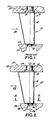
- FIG. 1 of the drawing a prior art inlet guide vane for an axial flow air compressor used in an industrial gas turbine is shown in elevational view.
- the construction of the axial flow gas turbine compressor itself is well-known in the art and is omitted from the drawings, but includes a rotor with several stages of radially extending blades interspersed between stages of radially extending circumferentially spaced stationary blades or vanes. Air flowing through an annular passage defined in the frame is compressed as it passes alternately between rotating and stationary stages.
- a first row of stationary blades called inlet guide vanes is constructed so that the angle of the vanes with respect to the fluid flow can be altered. Commonly this is accomplished by mounting each of the vanes on a spindle which is rotatably mounted in the frame. An operating crank on each of the spindles outside of the frame is connected to a ring encircling the frame which is positioned by a servomechanism in response to the dictates of the control system.
- the vanes may be varied between an "open” position where they provide only slight deflection of the air into the first stage of rotating compressor blades and a "closed” position where they provide maximum deflection of the fluid.
- a variable inlet guide vane assembly is indicated generally at reference number 10.
- the guide vane assembly comprises an airfoil-shaped vane 12, a platform 14 and a spindle 16 with an axis of rotation 18.
- the vane 12 is one of a circumferential row of radially extending circumferentially-spaced vanes supported in a gas turbine frame shown generally at 20.
- Frame 20 includes an outer annular casing 22 and an inner annular casing member 24 defining together between them an annular passage 26 for the axial flow of fluid, in this case air, in the direction shown by the arrow.
- the outer frame member 22 includes circumferentially-spaced spindle journal bearings 28 which rotatably support the spindles 16 and permit rotation of the vanes 12.
- Means (not shown) are provided exterior to the frame 20 in known manner to cause the vanes to pivot in unison.
- the inner frame member 24 includes a number of circumferentially-spaced inner bushings 30.
- Each of the vane assemblies 10 includes a cylindrical radially projecting button 32 which is contained within one of the bushings 30 with close clearances.
- the primary support of the vane is from its outer spindle 16.
- the radially inner end of each vane is subject to deflection and vibratory excitation from the aerodynamic forces of the turbulent fluid flowing through the annular passage 26.
- buttons 32 contact the walls of bushings 30 to restrain further movement and suppress vibration.
- the button 32 has been coaxial with spindle 16.
- Fig. 2 utilizes the same reference numerals as Fig. 1 where elements are the same.
- the radially inner portion of the vane is supplied with a cylindrical radially extending button 34 which has a central axis 36.
- Axis 36 of button 34 is offset in a preselected direction and by a preselected amount designed to minimize and suppress vibration as will be explained.
- the inner frame member 24 has a number of circumferentially-spaced bushings 38 which contain the respective buttons 34 with close clearances, preferably with a uniform circumferential clearance (see Fig. 3) in the absence of air flow through the compressor.
- FIG. 3 plan views are shown in order to illustrate the operation under different conditions.
- the reference numerals correspond to those of Fig. 2, but the respective sizes of the parts are not necessarily to scale, in order to illustrate the operation.
- the axis of rotation of the inlet guide vane assembly is shown at reference number 18.
- FIG. 3 shows that the axis 36 of button 34 is offset by a pre-selected distance preferably in a range of approximately .070 to .120 inches (1.78 to 3.05 mm) from the axis 18 of spindle 16.
- the offset is in a direction toward the bottom of the drawing, ie, toward the downstream direction of the flow of air through the compressor.
- Fig. 3 illustrates the position of the button 34 centered within the bushing 38 in the absence of flow, so as to provide a uniform circumferential clearance designated 40, perferably in a range of .01 to .05 inches (0.25 to 1.25 mm) between button 34 and walls of bushing 38.
- Vane 12 is shown rotated to a "closed" position.
- Fig. 4 of the drawing illustrates the vane 12 in the closed position similar to Fig. 3, but in the presence of air flow through the compressor.
- the button 34 is caused by the aerodynamic forces of air on vane 12 in its closed position to deflect approximately to the location indicated by arrow 44 and press there against the wall of bushing 38. This is due to aerodynamic forces on vane 12 in the closed position rather than due to eccentricity of button 34 when the vane is rotated.
- vane 12 is shown rotated to an "open" position about the axis 18 of spindle 16.
- the eccentrically offset axis 36 of button 34 is rotated clockwise through a vane rotation angle designated 42. Since button 34 is no longer centered within the bushing, it presses against the wall of bushing 38 at a location denoted by arrow 46. Location 46 is approximately the same as that toward which button 34 would be deflected due to aerodynamic forces of the air on vane 12 when the vane is in the "open" position shown.
- the compressor inlet guide vanes are pivoted in unison to selected positions in accordance with the operating requirements of the gas turbine. Rotation about spindles 18 without binding is permitted by the circumferential clearance 40 indicated in Fig. 3.
- the vane button need not be circular, the only requirement being that a projection which is eccentrically-offset with respect to the axis of rotation is arranged to cooperate with a portion of the stationary frame.
- the invention has been illustrated in the context of inlet guide vanes for an axial flow air compressor, the same principles are applicable to variable position inlet vanes of any shape or orientation in compressors for fluids of all types, where the airfoils experience greater or lesser aerodynamic forces in different orientations.
Landscapes
- Engineering & Computer Science (AREA)
- Mechanical Engineering (AREA)
- General Engineering & Computer Science (AREA)
- Structures Of Non-Positive Displacement Pumps (AREA)
Applications Claiming Priority (2)
| Application Number | Priority Date | Filing Date | Title |
|---|---|---|---|
| US312264 | 1989-02-21 | ||
| US07/312,264 US4950129A (en) | 1989-02-21 | 1989-02-21 | Variable inlet guide vanes for an axial flow compressor |
Publications (2)
| Publication Number | Publication Date |
|---|---|
| EP0384706A1 true EP0384706A1 (fr) | 1990-08-29 |
| EP0384706B1 EP0384706B1 (fr) | 1993-04-14 |
Family
ID=23210638
Family Applications (1)
| Application Number | Title | Priority Date | Filing Date |
|---|---|---|---|
| EP90301806A Expired - Lifetime EP0384706B1 (fr) | 1989-02-21 | 1990-02-20 | Aubes de redresseur à calage variable pour compresseur |
Country Status (4)
| Country | Link |
|---|---|
| US (1) | US4950129A (fr) |
| EP (1) | EP0384706B1 (fr) |
| JP (1) | JPH02248694A (fr) |
| DE (1) | DE69001310T2 (fr) |
Cited By (6)
| Publication number | Priority date | Publication date | Assignee | Title |
|---|---|---|---|---|
| GB2289726A (en) * | 1994-05-25 | 1995-11-29 | Gen Electric | Stator vane support |
| FR2771447A1 (fr) * | 1997-11-27 | 1999-05-28 | Daimler Benz Ag | Turbine a flux radial de turbocompresseur a gaz d'echappement |
| WO2010079204A1 (fr) * | 2009-01-09 | 2010-07-15 | Snecma | Aube a calage variable pour etage de redresseur, comprenant une plateforme interne non circulaire |
| CN102322298A (zh) * | 2011-08-25 | 2012-01-18 | 中国南方航空工业(集团)有限公司 | 涡轮导向器及涡轮机 |
| CN104781509A (zh) * | 2012-11-16 | 2015-07-15 | 通用电气公司 | 波状的定子护罩 |
| CN111527293A (zh) * | 2017-12-19 | 2020-08-11 | 西门子股份公司 | 压气机控制 |
Families Citing this family (26)
| Publication number | Priority date | Publication date | Assignee | Title |
|---|---|---|---|---|
| EP0417433B1 (fr) * | 1989-09-12 | 1993-06-09 | Asea Brown Boveri Ag | Turbine axiale |
| US6134876A (en) * | 1997-11-26 | 2000-10-24 | General Electric Company | Gas turbine engine with exhaust expander and compressor |
| JP2001193695A (ja) * | 2000-01-12 | 2001-07-17 | Mitsubishi Heavy Ind Ltd | 圧縮機 |
| US6412269B1 (en) | 2000-05-22 | 2002-07-02 | General Electric Company | Method for operating an engine system including a gas turbine engine, an inverted Brayton cycle apparatus having blow-in doors and blow-out doors for engine protection |
| US6450763B1 (en) | 2000-11-17 | 2002-09-17 | General Electric Company | Replaceable variable stator vane for gas turbines |
| US6619916B1 (en) | 2002-02-28 | 2003-09-16 | General Electric Company | Methods and apparatus for varying gas turbine engine inlet air flow |
| TW577194B (en) * | 2002-11-08 | 2004-02-21 | Endpoints Technology Corp | Digital adjustable chip oscillator |
| US6886343B2 (en) | 2003-01-15 | 2005-05-03 | General Electric Company | Methods and apparatus for controlling engine clearance closures |
| US7093419B2 (en) * | 2003-07-02 | 2006-08-22 | General Electric Company | Methods and apparatus for operating gas turbine engine combustors |
| US6955038B2 (en) * | 2003-07-02 | 2005-10-18 | General Electric Company | Methods and apparatus for operating gas turbine engine combustors |
| US7040096B2 (en) * | 2003-09-08 | 2006-05-09 | General Electric Company | Methods and apparatus for supplying feed air to turbine combustors |
| US7051532B2 (en) * | 2003-10-17 | 2006-05-30 | General Electric Company | Methods and apparatus for film cooling gas turbine engine combustors |
| US7036316B2 (en) * | 2003-10-17 | 2006-05-02 | General Electric Company | Methods and apparatus for cooling turbine engine combustor exit temperatures |
| US7310952B2 (en) * | 2003-10-17 | 2007-12-25 | General Electric Company | Methods and apparatus for attaching swirlers to gas turbine engine combustors |
| FR2920469A1 (fr) * | 2007-08-30 | 2009-03-06 | Snecma Sa | Aube a calage variable de turbomachine |
| DE102008021683A1 (de) * | 2008-04-30 | 2009-11-05 | Rolls-Royce Deutschland Ltd & Co Kg | Rotierende Einheit für einen Axialkompressor |
| US8123471B2 (en) * | 2009-03-11 | 2012-02-28 | General Electric Company | Variable stator vane contoured button |
| US9394804B2 (en) | 2012-01-24 | 2016-07-19 | Florida Institute Of Technology | Apparatus and method for rotating fluid controlling vanes in small turbine engines and other applications |
| US8528312B1 (en) * | 2013-01-08 | 2013-09-10 | Ali A. A. J. Shammoh | Turbojet engine inlet and exhaust covers |
| DE102013222980A1 (de) * | 2013-11-12 | 2015-06-11 | MTU Aero Engines AG | Leitschaufel für eine Strömungsmaschine mit einer Dichtungsvorrichtung, Leitrad sowie Strömungsmaschine |
| US10208619B2 (en) * | 2015-11-02 | 2019-02-19 | Florida Turbine Technologies, Inc. | Variable low turbine vane with aft rotation axis |
| US10704411B2 (en) | 2018-08-03 | 2020-07-07 | General Electric Company | Variable vane actuation system for a turbo machine |
| DE102019200885A1 (de) | 2019-01-24 | 2020-07-30 | MTU Aero Engines AG | Leitgitter für eine Strömungsmaschine |
| DE102020210094A1 (de) | 2020-08-10 | 2022-02-10 | MTU Aero Engines AG | Verstellbare Leitschaufelanordnung |
| US11674400B2 (en) * | 2021-03-12 | 2023-06-13 | Ge Avio S.R.L. | Gas turbine engine nozzles |
| US11970948B2 (en) * | 2022-08-09 | 2024-04-30 | Pratt & Whitney Canada Corp. | Variable vane airfoil with airfoil twist to accommodate protuberance |
Citations (6)
| Publication number | Priority date | Publication date | Assignee | Title |
|---|---|---|---|---|
| US3042370A (en) * | 1957-10-07 | 1962-07-03 | Gen Motors Corp | Vane ring assembly |
| US3070352A (en) * | 1957-11-06 | 1962-12-25 | Gen Motors Corp | Vane ring assembly |
| US3314654A (en) * | 1965-07-30 | 1967-04-18 | Gen Electric | Variable area turbine nozzle for axial flow gas turbine engines |
| CH491288A (de) * | 1968-05-20 | 1970-05-31 | Sulzer Ag | Halterung für den Leitschaufelträger einer mehrstufigen Gasturbine |
| FR2106561A1 (fr) * | 1970-09-16 | 1972-05-05 | United Kingdom Government | |
| DE2165529A1 (de) * | 1971-12-30 | 1973-07-05 | Kloeckner Humboldt Deutz Ag | Einrichtung zum zentrieren und fixieren eines koerpers |
Family Cites Families (8)
| Publication number | Priority date | Publication date | Assignee | Title |
|---|---|---|---|---|
| DE25275C (de) * | W. MORRIS in Oakengates, County of | Bewegliche Wenderohre für Walzwerke | ||
| NL86599C (fr) * | 1955-06-17 | |||
| US2985427A (en) * | 1955-11-25 | 1961-05-23 | Gen Electric | Adjustable blading for fluid flow machines |
| FR1257377A (fr) * | 1959-07-01 | 1961-03-31 | Vevey Atel Const Mec | Distributeur à aubes mobiles destiné à une turbine à basse chute |
| US3101926A (en) * | 1960-09-01 | 1963-08-27 | Garrett Corp | Variable area nozzle device |
| CH423669A (de) * | 1965-06-04 | 1966-10-31 | Escher Wyss Ag | Regulierbarer Leitapparat einer Wasserturbine oder Pumpe |
| US3887297A (en) * | 1974-06-25 | 1975-06-03 | United Aircraft Corp | Variable leading edge stator vane assembly |
| US4770605A (en) * | 1981-02-16 | 1988-09-13 | Mitsubishi Jukogyo Kabushiki Kaisha | Diffuser device in a centrifugal compressor and method for manufacturing the same |
-
1989
- 1989-02-21 US US07/312,264 patent/US4950129A/en not_active Expired - Fee Related
-
1990
- 1990-02-20 EP EP90301806A patent/EP0384706B1/fr not_active Expired - Lifetime
- 1990-02-20 DE DE9090301806T patent/DE69001310T2/de not_active Expired - Fee Related
- 1990-02-20 JP JP2037545A patent/JPH02248694A/ja active Pending
Patent Citations (6)
| Publication number | Priority date | Publication date | Assignee | Title |
|---|---|---|---|---|
| US3042370A (en) * | 1957-10-07 | 1962-07-03 | Gen Motors Corp | Vane ring assembly |
| US3070352A (en) * | 1957-11-06 | 1962-12-25 | Gen Motors Corp | Vane ring assembly |
| US3314654A (en) * | 1965-07-30 | 1967-04-18 | Gen Electric | Variable area turbine nozzle for axial flow gas turbine engines |
| CH491288A (de) * | 1968-05-20 | 1970-05-31 | Sulzer Ag | Halterung für den Leitschaufelträger einer mehrstufigen Gasturbine |
| FR2106561A1 (fr) * | 1970-09-16 | 1972-05-05 | United Kingdom Government | |
| DE2165529A1 (de) * | 1971-12-30 | 1973-07-05 | Kloeckner Humboldt Deutz Ag | Einrichtung zum zentrieren und fixieren eines koerpers |
Cited By (16)
| Publication number | Priority date | Publication date | Assignee | Title |
|---|---|---|---|---|
| GB2289726A (en) * | 1994-05-25 | 1995-11-29 | Gen Electric | Stator vane support |
| GB2289726B (en) * | 1994-05-25 | 1998-02-04 | Gen Electric | Stator vane housing |
| FR2771447A1 (fr) * | 1997-11-27 | 1999-05-28 | Daimler Benz Ag | Turbine a flux radial de turbocompresseur a gaz d'echappement |
| GB2331790A (en) * | 1997-11-27 | 1999-06-02 | Daimler Benz Ag | Radial flow exhaust-gas turbocharger guide blades |
| US6050775A (en) * | 1997-11-27 | 2000-04-18 | Daimlerchrysler Ag | Radial-flow exhaust-gas turbocharger turbine |
| GB2331790B (en) * | 1997-11-27 | 2000-05-17 | Daimler Benz Ag | Turbocharger including a radial-flow exhaust-gas turbocharger turbine |
| CN102272458A (zh) * | 2009-01-09 | 2011-12-07 | 斯奈克玛 | 静子级的变螺距叶片,包括非圆形内平台 |
| FR2941018A1 (fr) * | 2009-01-09 | 2010-07-16 | Snecma | Aube a calage variable pour etage de redresseur, comprenant une plateforme interne non circulaire |
| WO2010079204A1 (fr) * | 2009-01-09 | 2010-07-15 | Snecma | Aube a calage variable pour etage de redresseur, comprenant une plateforme interne non circulaire |
| CN102272458B (zh) * | 2009-01-09 | 2014-04-09 | 斯奈克玛 | 静子级的变螺距叶片,包括非圆形内平台 |
| US8721269B2 (en) | 2009-01-09 | 2014-05-13 | Snecma | Variable-pitch vane for stator stage, including a non-circular inner platform |
| CN102322298A (zh) * | 2011-08-25 | 2012-01-18 | 中国南方航空工业(集团)有限公司 | 涡轮导向器及涡轮机 |
| CN102322298B (zh) * | 2011-08-25 | 2014-04-30 | 中国南方航空工业(集团)有限公司 | 涡轮导向器及涡轮机 |
| CN104781509A (zh) * | 2012-11-16 | 2015-07-15 | 通用电气公司 | 波状的定子护罩 |
| CN111527293A (zh) * | 2017-12-19 | 2020-08-11 | 西门子股份公司 | 压气机控制 |
| CN111527293B (zh) * | 2017-12-19 | 2023-04-21 | 西门子能源环球有限责任两合公司 | 压气机控制 |
Also Published As
| Publication number | Publication date |
|---|---|
| DE69001310T2 (de) | 1993-08-26 |
| JPH02248694A (ja) | 1990-10-04 |
| DE69001310D1 (de) | 1993-05-19 |
| EP0384706B1 (fr) | 1993-04-14 |
| US4950129A (en) | 1990-08-21 |
Similar Documents
| Publication | Publication Date | Title |
|---|---|---|
| EP0384706B1 (fr) | Aubes de redresseur à calage variable pour compresseur | |
| EP4008884B1 (fr) | Ensemble d'aubes directrices variables pour un moteur à turbine à gaz et moteur à turbine à gaz | |
| EP2659096B1 (fr) | Aube variable pour moteur à turbine à gaz | |
| US11460047B2 (en) | Throttle mechanism for centrifugal compressor and turbocharger | |
| CN106948871B (zh) | 可变定子导叶底切扣状体 | |
| EP1234950B1 (fr) | Système de réglage des aubes de turbine et procédé de réalisation | |
| KR102027695B1 (ko) | 스크롤 압축기 | |
| US10975886B2 (en) | Turbocharger | |
| US6808364B2 (en) | Methods and apparatus for sealing gas turbine engine variable vane assemblies | |
| JP2009150363A (ja) | 可変ノズル機構を備えた可変容量型排気ターボ過給機 | |
| US5796199A (en) | Pivoting vane internal extremity bearing | |
| EP2581556A2 (fr) | Aubes variables avec inclinaison non uniforme | |
| US3295827A (en) | Variable configuration blade | |
| EP1792054B1 (fr) | Diffuseur radial a surface variable | |
| US11118508B2 (en) | Variable displacement turbocharger | |
| US10662871B2 (en) | Nozzle drive mechanism, turbocharger, variable capacity turbocharger | |
| CN107795525B (zh) | 轴式涡轮机压缩机的内叶冠和可取向叶片 | |
| US8366380B2 (en) | Turbo-molecular pump and method of assembling turbo-molecular pump | |
| EP3705698A1 (fr) | Turbine et turbocompresseur | |
| EP3722564B1 (fr) | Agencement de levier d'aube directrice pour moteur à turbine à gaz, procéde de rétention axiale redondante d'un levier d'aube directrice et moteur à turbine à gaz associés | |
| US20170159467A1 (en) | Guide vane ring casing for a turbomachine and turbomachine having a guide vane ring casing | |
| EP1031703A2 (fr) | Dispositifs de commande d'aubes directrices | |
| US11215190B2 (en) | Centrifugal compressor | |
| JP2009299528A (ja) | ターボ機械 | |
| EP3913200B1 (fr) | Structure de palier lisse et compresseur de suralimentation équipé de cette dernière |
Legal Events
| Date | Code | Title | Description |
|---|---|---|---|
| PUAI | Public reference made under article 153(3) epc to a published international application that has entered the european phase |
Free format text: ORIGINAL CODE: 0009012 |
|
| AK | Designated contracting states |
Kind code of ref document: A1 Designated state(s): CH DE FR GB IT LI |
|
| 17P | Request for examination filed |
Effective date: 19901210 |
|
| 17Q | First examination report despatched |
Effective date: 19920109 |
|
| GRAA | (expected) grant |
Free format text: ORIGINAL CODE: 0009210 |
|
| AK | Designated contracting states |
Kind code of ref document: B1 Designated state(s): CH DE FR GB IT LI |
|
| ITF | It: translation for a ep patent filed | ||
| REF | Corresponds to: |
Ref document number: 69001310 Country of ref document: DE Date of ref document: 19930519 |
|
| ET | Fr: translation filed | ||
| PLBE | No opposition filed within time limit |
Free format text: ORIGINAL CODE: 0009261 |
|
| STAA | Information on the status of an ep patent application or granted ep patent |
Free format text: STATUS: NO OPPOSITION FILED WITHIN TIME LIMIT |
|
| PG25 | Lapsed in a contracting state [announced via postgrant information from national office to epo] |
Ref country code: GB Effective date: 19940220 |
|
| PG25 | Lapsed in a contracting state [announced via postgrant information from national office to epo] |
Ref country code: LI Effective date: 19940228 Ref country code: CH Effective date: 19940228 |
|
| 26N | No opposition filed | ||
| GBPC | Gb: european patent ceased through non-payment of renewal fee |
Effective date: 19940220 |
|
| PG25 | Lapsed in a contracting state [announced via postgrant information from national office to epo] |
Ref country code: FR Effective date: 19941031 |
|
| REG | Reference to a national code |
Ref country code: CH Ref legal event code: PL |
|
| PG25 | Lapsed in a contracting state [announced via postgrant information from national office to epo] |
Ref country code: DE Effective date: 19941101 |
|
| REG | Reference to a national code |
Ref country code: FR Ref legal event code: ST |
|
| PG25 | Lapsed in a contracting state [announced via postgrant information from national office to epo] |
Ref country code: IT Free format text: LAPSE BECAUSE OF NON-PAYMENT OF DUE FEES;WARNING: LAPSES OF ITALIAN PATENTS WITH EFFECTIVE DATE BEFORE 2007 MAY HAVE OCCURRED AT ANY TIME BEFORE 2007. THE CORRECT EFFECTIVE DATE MAY BE DIFFERENT FROM THE ONE RECORDED. Effective date: 20050220 |