EP0386427A2 - Installation à arc électrique pour la pulvérisation à haut rendement de fils pleins ou de remplissage - Google Patents
Installation à arc électrique pour la pulvérisation à haut rendement de fils pleins ou de remplissage Download PDFInfo
- Publication number
- EP0386427A2 EP0386427A2 EP19900101386 EP90101386A EP0386427A2 EP 0386427 A2 EP0386427 A2 EP 0386427A2 EP 19900101386 EP19900101386 EP 19900101386 EP 90101386 A EP90101386 A EP 90101386A EP 0386427 A2 EP0386427 A2 EP 0386427A2
- Authority
- EP
- European Patent Office
- Prior art keywords
- arc
- arc spraying
- spraying system
- nozzles
- contact
- Prior art date
- Legal status (The legal status is an assumption and is not a legal conclusion. Google has not performed a legal analysis and makes no representation as to the accuracy of the status listed.)
- Withdrawn
Links
- 238000005507 spraying Methods 0.000 title claims abstract description 34
- 239000007787 solid Substances 0.000 title claims description 8
- 238000009434 installation Methods 0.000 title 1
- 239000007789 gas Substances 0.000 claims abstract description 53
- 239000007921 spray Substances 0.000 claims abstract description 51
- 239000000203 mixture Substances 0.000 claims abstract description 7
- 229910000906 Bronze Inorganic materials 0.000 claims abstract description 4
- 229910000831 Steel Inorganic materials 0.000 claims abstract description 4
- 239000010974 bronze Substances 0.000 claims abstract description 4
- KUNSUQLRTQLHQQ-UHFFFAOYSA-N copper tin Chemical compound [Cu].[Sn] KUNSUQLRTQLHQQ-UHFFFAOYSA-N 0.000 claims abstract description 4
- 239000010959 steel Substances 0.000 claims abstract description 4
- 239000012530 fluid Substances 0.000 claims abstract description 3
- 239000002245 particle Substances 0.000 claims description 17
- XKRFYHLGVUSROY-UHFFFAOYSA-N Argon Chemical compound [Ar] XKRFYHLGVUSROY-UHFFFAOYSA-N 0.000 claims description 8
- IJGRMHOSHXDMSA-UHFFFAOYSA-N Atomic nitrogen Chemical compound N#N IJGRMHOSHXDMSA-UHFFFAOYSA-N 0.000 claims description 8
- 230000005540 biological transmission Effects 0.000 claims description 5
- 229910052786 argon Inorganic materials 0.000 claims description 4
- 229910052757 nitrogen Inorganic materials 0.000 claims description 4
- 239000003570 air Substances 0.000 claims description 3
- XLYOFNOQVPJJNP-UHFFFAOYSA-N water Substances O XLYOFNOQVPJJNP-UHFFFAOYSA-N 0.000 claims description 2
- 239000011241 protective layer Substances 0.000 abstract description 5
- 238000005260 corrosion Methods 0.000 abstract description 4
- 230000007797 corrosion Effects 0.000 abstract description 4
- 238000007751 thermal spraying Methods 0.000 abstract description 3
- 238000002844 melting Methods 0.000 description 13
- 230000008018 melting Effects 0.000 description 11
- 238000000889 atomisation Methods 0.000 description 5
- 239000010410 layer Substances 0.000 description 4
- VNWKTOKETHGBQD-UHFFFAOYSA-N methane Chemical compound C VNWKTOKETHGBQD-UHFFFAOYSA-N 0.000 description 4
- 238000000034 method Methods 0.000 description 4
- RYGMFSIKBFXOCR-UHFFFAOYSA-N Copper Chemical compound [Cu] RYGMFSIKBFXOCR-UHFFFAOYSA-N 0.000 description 3
- 239000000919 ceramic Substances 0.000 description 3
- 229910052802 copper Inorganic materials 0.000 description 3
- 239000010949 copper Substances 0.000 description 3
- 239000000956 alloy Substances 0.000 description 2
- 229910045601 alloy Inorganic materials 0.000 description 2
- 230000003628 erosive effect Effects 0.000 description 2
- 238000010285 flame spraying Methods 0.000 description 2
- 230000003647 oxidation Effects 0.000 description 2
- 238000007254 oxidation reaction Methods 0.000 description 2
- 230000021715 photosynthesis, light harvesting Effects 0.000 description 2
- 238000007750 plasma spraying Methods 0.000 description 2
- 101000793686 Homo sapiens Azurocidin Proteins 0.000 description 1
- 230000001133 acceleration Effects 0.000 description 1
- 230000001464 adherent effect Effects 0.000 description 1
- 239000011362 coarse particle Substances 0.000 description 1
- 239000011248 coating agent Substances 0.000 description 1
- 238000000576 coating method Methods 0.000 description 1
- 238000007796 conventional method Methods 0.000 description 1
- 238000001816 cooling Methods 0.000 description 1
- 230000001419 dependent effect Effects 0.000 description 1
- 230000008021 deposition Effects 0.000 description 1
- 238000010891 electric arc Methods 0.000 description 1
- 238000010438 heat treatment Methods 0.000 description 1
- 239000000463 material Substances 0.000 description 1
- 239000000155 melt Substances 0.000 description 1
- 239000002184 metal Substances 0.000 description 1
- 229910052751 metal Inorganic materials 0.000 description 1
- 239000003345 natural gas Substances 0.000 description 1
- TWNQGVIAIRXVLR-UHFFFAOYSA-N oxo(oxoalumanyloxy)alumane Chemical compound O=[Al]O[Al]=O TWNQGVIAIRXVLR-UHFFFAOYSA-N 0.000 description 1
- 230000002028 premature Effects 0.000 description 1
- 238000004886 process control Methods 0.000 description 1
- 230000005855 radiation Effects 0.000 description 1
- 230000001105 regulatory effect Effects 0.000 description 1
- 230000002787 reinforcement Effects 0.000 description 1
- 239000000758 substrate Substances 0.000 description 1
Images

Classifications
-
- B—PERFORMING OPERATIONS; TRANSPORTING
- B05—SPRAYING OR ATOMISING IN GENERAL; APPLYING FLUENT MATERIALS TO SURFACES, IN GENERAL
- B05B—SPRAYING APPARATUS; ATOMISING APPARATUS; NOZZLES
- B05B7/00—Spraying apparatus for discharge of liquids or other fluent materials from two or more sources, e.g. of liquid and air, of powder and gas
- B05B7/16—Spraying apparatus for discharge of liquids or other fluent materials from two or more sources, e.g. of liquid and air, of powder and gas incorporating means for heating or cooling the material to be sprayed
- B05B7/22—Spraying apparatus for discharge of liquids or other fluent materials from two or more sources, e.g. of liquid and air, of powder and gas incorporating means for heating or cooling the material to be sprayed electrically, magnetically or electromagnetically, e.g. by arc
- B05B7/222—Spraying apparatus for discharge of liquids or other fluent materials from two or more sources, e.g. of liquid and air, of powder and gas incorporating means for heating or cooling the material to be sprayed electrically, magnetically or electromagnetically, e.g. by arc using an arc
- B05B7/224—Spraying apparatus for discharge of liquids or other fluent materials from two or more sources, e.g. of liquid and air, of powder and gas incorporating means for heating or cooling the material to be sprayed electrically, magnetically or electromagnetically, e.g. by arc using an arc the material having originally the shape of a wire, rod or the like
Definitions
- the invention relates to an arc spraying system for high-performance spraying of solid and cored wires.
- an atomizer nozzle arranged centrally behind the melting wire electrodes or an additional nozzle is used which gives an atomizing gas flow acting in the radial direction on the spray jet (DE 3533966, DE 2821889 and EP 0051869).
- the achievable speed of the atomizing gas at the melting point at the height of the wire tips is a maximum of approx. 300 m / s and the spray particle speed between approx. 30 - 80 m / s (conference proceedings "2nd Int. Conf. On Surface Engineering", England, 1987, paper 39), although to achieve good adherent, dense and homogeneous protective layers a higher gas and particle speed, as with other thermal spray processes with a lower application rate, eg plasma spraying and high-speed flame spraying (magazine "face und JOT ", year 1988, issue 9, Pages 30 to 39) is required. In this way, in particular a finer atomization and a higher kinetic energy of the spray particles are achieved on impact on the workpiece to be coated.
- the present invention aims to overcome the disadvantages mentioned.
- the invention has for its object to develop an arc spraying system for high-performance spraying of solid and cored wires, which in particular in a cost-effective manner, i.e. With high application rates, the reinforcement of large components, such as rollers, shafts, containers, with high-quality wear and corrosion-resistant protective layers.
- an arc spraying system is used for high-performance spraying, which is equipped with two separately controllable nozzles for accelerating and atomizing the spray particles (melt), which produce two independent supersonic flows.
- a controlled expansion of the atomizing gas is achieved by using two independently adjustable nozzles in the form of so-called Laval nozzles. This makes it possible to keep the energy dissipation small and to achieve supersonic gas velocity, i.e. the momentum transfer of the atomizing gas to the spray particles is significantly increased.
- the atomizing gas used is preferably preheated by means of electrically heated heat exchangers before entering the nozzles inside and / or outside the spray gun belonging to the arc system.
- the expandability and thus the exit speed of the atomizing gas are drastically increased as a result of the increase in volume of the atomizing gas associated with this preheating, and finer atomization and a considerable increase in the speed of the spray particles are achieved even with very high electrical power consumption by the spray gun.
- the contact nozzles with springs e.g. made of steel or bronze.
- the contact nozzles are inside by a gas flow independent of the atomizing gas, e.g. Air, argon, nitrogen or other fluids such as water are cooled.
- a gas flow independent of the atomizing gas e.g. Air, argon, nitrogen or other fluids such as water are cooled.
- the spray gun is equipped with a wire feed device, in which the contact pressure of the feed rollers can be adjusted continuously, or a wire feed device is used which conveys the wire outside the gun in the same way.
- the pneumatically or electrically operated wire feed is steplessly controlled by servomotors independently for both wires and the position of the contact nozzles separately for each contact nozzle .
- a high-melting ceramic cap preferably made of aluminum oxide, is used to guide both wires to close to the melting point. A centering of the wire tips is also possible with the aid of manually or electromotive actuating screws acting on the contact nozzles.
- the length and / or the geometric shape of the arc is used as a measure. Values from arithmetic operations with one or both of these variables can also be used for this regulation.
- the respective arc voltage and / or the current are preferably electronically compared with a predetermined setpoint. In order to maintain this setpoint, the feed speed of one spray wire or both spray wires is varied.
- a transferred arc can be used for preheating the workpiece to be coated and for arc spraying.
- the advantages achieved by the invention are, in particular, that high-quality wear-resistant and corrosion-resistant protective layers can be produced with the described arc spraying system at high application rates by spraying solid and cored wires.
- this arc spraying system for high-performance spraying compared to other conventional methods of thermal spraying, with which comparable high-quality layers can be produced, such as plasma spraying or high-speed flame spraying, application rates which are up to 10 times higher, i.e. up to approx. 30 kg / h, with system costs reduced by a factor of 3-6 at the same time.
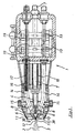
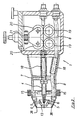
- FIG. 1 and 2 show diagrammatic representations of a spray gun belonging to the arc spraying system in section.
- the spray gun generally designated 1
- These nozzles are supplied with the atomizing gas independently of one another by two infinitely variable supply lines 7, 8 using needle, ball or solenoid valves (not shown in the drawing).
- a gas velocity of up to about 500 m / s is achieved and at the same time by using inert and active gases, such as argon, nitrogen, methane, natural gas or their gas mixtures, as the enveloping gas the erosion of alloy elements due to the resulting reduction in oxidation by the surrounding atmosphere is considerably reduced.
- inert and active gases such as argon, nitrogen, methane, natural gas or their gas mixtures
- a high-melting ceramic cap 13 is preferably used. Centering of the spray wires 9, 10 is also possible with the aid of adjusting screws 15 acting on contact nozzles 14.
- the contact nozzles 14 used for the current transmission to the spray wires 9, 10, preferably made of copper, have steel or bronze springs 16 on the inside for low-loss and low-wear transmission of the electrical current.
- these are used to increase the electrical power consumption and to achieve a small size of the spray gun 1 by means of a further gas stream 17 which is independent of the atomizing gas, e.g. consisting of air, argon, nitrogen, cooled inside.
- the arc spray gun for preheating the atomizing gas is preferably equipped with two separately controllable electrical heat exchangers 18.
- This preheating up to approx. 750 ° C increases the speed of the atomizing gas by more than 100% compared to conventional spray guns, i.e. up to approx. Achieve 800 m / s.
- the two spray wires 9, 10 are transported during the spraying process with a wire feed device, preferably consisting of four driven feed rollers 19 and four idle rollers 20.
- the contact pressure of the pneumatically or electrically driven ones Feed rollers 19 are continuously adjustable depending on the ductility, the mechanical stability and the diameter of the wires used.
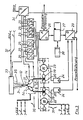
- process-dependent parameters preferably the arc voltage, which is a measure of the length and / or geometric shape of the arc 12 blown by the atomizing gas, are used as a measure of the feed control 24 via a measuring transducer 25 and an analog-digital converter 26 with a microcomputer Memory 27 supplied.
- the input data are compared with the target values specified by an operator unit 28. The resulting differences between target and actual values are calculated numerically and fed to the feed control 24 via a digital-to-analog converter 29 to correct the wire feed.
- the spray wire 9 is advanced more quickly via the feed control 24 with the aid of the servo motor 22 in order to achieve the desired value of the voltage.
- the advance of the spray wire 9 is slowed down until the target value is set.
- the feed speed of the feed motor 23 for the spray wire 10 remains constant during the control process.
- the position of the contact nozzles 14 can be regulated in the same way.
- control loops 30, 31, 32 can be seen for further explanation. As shown in the following, these can intervene in the workflow during the application of the coating via parameter acquisition and process control.
- the control circuit 30 thus enables the two contact nozzles 14 to be positioned independently of one another via an electromechanical adjustment (not shown in the drawing) in the x-y-z direction. In this way, in addition to the feed control 24 of the spray wires 9, 10, it is possible to center the wire tips at the level of the melting point 11 in a simple manner and to quickly achieve a stable arc 12.
- this control circuit 30 independently detects the temperature and pressure of the atomizing gas for both high-speed nozzles 4, 5 and the temperature of the internally cooled contact nozzles 14.
- the contact pressure of the feed rollers 19 and the slip between the feed speed of the spray wires 9, 10 and the speed of the feed rollers 19 are controlled independently by the control circuit 31 for both spray wires 9, 10.
- the workpiece 33 to be coated can be positioned in the x-y-z direction via servo drives (not shown in the drawing) and the temperature of a workpiece 33 can be detected.
- Negative or positive electrical polarity of the workpiece 33 relative to the spray wires 9, 10 also makes it possible to preheat the workpiece 33 or arc spray by means of a transmitted arc 35, for example by contact or high-frequency ignition and using an electronically controllable current source 34.
- FIG. 4 shows an example of the configuration of a high-speed ring nozzle 36 with a blind cap 37 for further explanation.
- the outflow angle 39 of the high-speed ring nozzle 35 can also be 3-38 ° in order to be able to exert stronger shear forces on the spray particles 2 and thereby achieve a finer atomization.
Landscapes
- Physics & Mathematics (AREA)
- Electromagnetism (AREA)
- Coating By Spraying Or Casting (AREA)
- Nozzles (AREA)
Applications Claiming Priority (2)
| Application Number | Priority Date | Filing Date | Title |
|---|---|---|---|
| DE3902736 | 1989-01-31 | ||
| DE19893902736 DE3902736A1 (de) | 1989-01-31 | 1989-01-31 | Lichtbogenspritzanlage zum hochleistungsspritzen von massiv- und fuelldraehten |
Publications (2)
| Publication Number | Publication Date |
|---|---|
| EP0386427A2 true EP0386427A2 (fr) | 1990-09-12 |
| EP0386427A3 EP0386427A3 (fr) | 1991-09-18 |
Family
ID=6373093
Family Applications (1)
| Application Number | Title | Priority Date | Filing Date |
|---|---|---|---|
| EP19900101386 Withdrawn EP0386427A3 (fr) | 1989-01-31 | 1990-01-24 | Installation à arc électrique pour la pulvérisation à haut rendement de fils pleins ou de remplissage |
Country Status (2)
| Country | Link |
|---|---|
| EP (1) | EP0386427A3 (fr) |
| DE (1) | DE3902736A1 (fr) |
Cited By (6)
| Publication number | Priority date | Publication date | Assignee | Title |
|---|---|---|---|---|
| RU2162749C2 (ru) * | 1999-01-05 | 2001-02-10 | Государственное объединение "Уральский завод транспортного машиностроения" | Устройство для электродуговой металлизации |
| DE10204252A1 (de) * | 2002-02-02 | 2003-08-14 | Daimler Chrysler Ag | Verfahren und Spitzpistole zum Lichtbogenspritzen |
| DE102005012360A1 (de) * | 2005-03-17 | 2006-09-28 | Daimlerchrysler Ag | Lichtbogendrahtbrenner |
| WO2007091102A1 (fr) * | 2006-02-07 | 2007-08-16 | The Boc Group Plc | Appareil de pulverisation cinetique et procede |
| EP2468914A1 (fr) | 2010-12-23 | 2012-06-27 | Linde Aktiengesellschaft | Procédé et dispositif destinés à l'injection à arc électrique |
| CN113957377A (zh) * | 2021-10-20 | 2022-01-21 | 卡贝尼新材料科技(上海)有限公司 | 电弧喷涂金属涂层的工艺方法及系统 |
Families Citing this family (6)
| Publication number | Priority date | Publication date | Assignee | Title |
|---|---|---|---|---|
| DE4042276A1 (de) * | 1990-12-31 | 1992-07-02 | Castolin Sa | Vorrichtung und verfahren zum herstellen von schutzschichten |
| RU2254933C2 (ru) * | 2003-08-12 | 2005-06-27 | Литовченко Николай Николаевич | Электродуговой металлизатор |
| DE102008004607A1 (de) * | 2008-01-16 | 2009-05-28 | Daimler Ag | Lichtbogendrahtbrenner |
| CN107930885A (zh) * | 2017-12-19 | 2018-04-20 | 代卫东 | 一种可旋转内孔双丝电弧喷枪 |
| RU2687905C1 (ru) * | 2018-12-19 | 2019-05-16 | Федеральное государственное бюджетное научное учреждение "Федеральный научный агроинженерный центр ВИМ" (ФГБНУ ФНАЦ ВИМ) | Электродуговой металлизатор "Дракон" |
| CN110038747B (zh) * | 2019-04-17 | 2022-04-15 | 广东工业大学 | 一种电弧喷枪 |
Family Cites Families (6)
| Publication number | Priority date | Publication date | Assignee | Title |
|---|---|---|---|---|
| GB210759A (en) * | 1923-02-03 | 1924-09-11 | Electroquimica De Flix Soc | Improvements in apparatus for spraying and projecting molten metals |
| US3358114A (en) * | 1962-08-07 | 1967-12-12 | Inoue Kiyoshi | Method of and apparatus for the electric spray-coating of substrates |
| US3546415A (en) * | 1968-11-07 | 1970-12-08 | Flame Spray Ind Inc | Electric arc metallizing device |
| CH593754A5 (fr) * | 1976-01-15 | 1977-12-15 | Castolin Sa | |
| GB1554820A (en) * | 1978-05-11 | 1979-10-31 | Yoshagiken Kk | Electric arc spraying apparatus |
| US4370538A (en) * | 1980-05-23 | 1983-01-25 | Browning Engineering Corporation | Method and apparatus for ultra high velocity dual stream metal flame spraying |
-
1989
- 1989-01-31 DE DE19893902736 patent/DE3902736A1/de not_active Withdrawn
-
1990
- 1990-01-24 EP EP19900101386 patent/EP0386427A3/fr not_active Withdrawn
Cited By (8)
| Publication number | Priority date | Publication date | Assignee | Title |
|---|---|---|---|---|
| RU2162749C2 (ru) * | 1999-01-05 | 2001-02-10 | Государственное объединение "Уральский завод транспортного машиностроения" | Устройство для электродуговой металлизации |
| DE10204252A1 (de) * | 2002-02-02 | 2003-08-14 | Daimler Chrysler Ag | Verfahren und Spitzpistole zum Lichtbogenspritzen |
| DE102005012360A1 (de) * | 2005-03-17 | 2006-09-28 | Daimlerchrysler Ag | Lichtbogendrahtbrenner |
| DE102005012360B4 (de) * | 2005-03-17 | 2009-09-03 | Daimler Ag | Lichtbogendrahtbrenner |
| WO2007091102A1 (fr) * | 2006-02-07 | 2007-08-16 | The Boc Group Plc | Appareil de pulverisation cinetique et procede |
| EP2468914A1 (fr) | 2010-12-23 | 2012-06-27 | Linde Aktiengesellschaft | Procédé et dispositif destinés à l'injection à arc électrique |
| CN113957377A (zh) * | 2021-10-20 | 2022-01-21 | 卡贝尼新材料科技(上海)有限公司 | 电弧喷涂金属涂层的工艺方法及系统 |
| CN113957377B (zh) * | 2021-10-20 | 2023-09-01 | 卡贝尼新材料科技(上海)有限公司 | 电弧喷涂金属涂层的工艺方法及系统 |
Also Published As
| Publication number | Publication date |
|---|---|
| DE3902736A1 (de) | 1990-08-02 |
| EP0386427A3 (fr) | 1991-09-18 |
Similar Documents
| Publication | Publication Date | Title |
|---|---|---|
| DE69123152T2 (de) | Hochgeschwindigkeitslichtbogenspritzvorrichtung und verfahren zum formen von material | |
| DE3942050B4 (de) | Vorrichtung zur Laserplasmaspritzung mit axialer Strömung | |
| EP1999297B1 (fr) | Pistolet de projection a gaz froid | |
| DE3878570T2 (de) | Verfahren und apparat zum hochleistungsplasmaspritzen. | |
| EP3083107B1 (fr) | Dispositif et procédé de fusion en zone flottante d'un matériau et d'atomisation du matériau fondu pour fabriquer de la poudre | |
| DE69729805T2 (de) | Vorrichtung und verfahren von thermischem spritzen mit übertragenem lichtbogen | |
| DE10051907B4 (de) | Verfahren und Gerät zum thermischen Spritzen | |
| DE10128565B4 (de) | Thermisches Plasmaspritzen mit auf einen Draht übertragenem Lichtbogen mit hoher Abscheidungsgeschwindigkeit und Vorrichtung | |
| EP0386427A2 (fr) | Installation à arc électrique pour la pulvérisation à haut rendement de fils pleins ou de remplissage | |
| EP0808663A2 (fr) | Appareil de pulvérisation électrostatique | |
| DE2615679A1 (de) | Lichtbogen-metallspritzgeraet | |
| WO2021047821A1 (fr) | Unité de dépôt de matériau ayant une zone de focalisation de matériau multiple et procédé de soudage par rechargement | |
| DE10319481A1 (de) | Lavaldüse für das thermische Spritzen und das kinetische Spritzen | |
| DE2656330C2 (de) | Verfahren und Vorrichtung zur Herstellung von Pulvern oder Granulaten aus Metallen und Legierungen | |
| EP2785491B1 (fr) | Procédé pour réparer une aube directrice variable | |
| DE102012003307A1 (de) | Vorrichtung und Plasmaspritzverfahren zum Plasmabeschichten einer Oberfläche eines Substrats | |
| EP1147844B1 (fr) | Méthode de brasage plasma avec poudre | |
| DE8901020U1 (de) | Lichtbogenspritzpistole | |
| EP2622111B1 (fr) | Procédé et dispositif de projection thermique | |
| DE102018113643A1 (de) | Vorrichtung zur Beschichtung einer Oberfläche | |
| EP4082670B1 (fr) | Dispositif de revêtement thermique au moyen de la pulvérisation à fil à arc électrique | |
| DE3117715A1 (de) | "vorrichtung zum spruehbeschichten von gegenstaenden mit pulver" | |
| EP3990681B1 (fr) | Installation de pulvérisation par gaz froid à rayon de particules réglable | |
| EP0493695B1 (fr) | Appareillage de pulvérisation à fil | |
| DE3318931C2 (de) | Verfahren zum Spritzbeschichten von Gegenständen und Vorrichtung zur Durchführung des Verfahrens |
Legal Events
| Date | Code | Title | Description |
|---|---|---|---|
| PUAI | Public reference made under article 153(3) epc to a published international application that has entered the european phase |
Free format text: ORIGINAL CODE: 0009012 |
|
| AK | Designated contracting states |
Kind code of ref document: A2 Designated state(s): AT BE CH DE DK ES FR GB GR IT LI LU NL SE |
|
| 17P | Request for examination filed |
Effective date: 19901214 |
|
| PUAL | Search report despatched |
Free format text: ORIGINAL CODE: 0009013 |
|
| AK | Designated contracting states |
Kind code of ref document: A3 Designated state(s): AT BE CH DE DK ES FR GB GR IT LI LU NL SE |
|
| RAP1 | Party data changed (applicant data changed or rights of an application transferred) |
Owner name: BUSSE, KARL-HERMANN |
|
| RIN1 | Information on inventor provided before grant (corrected) |
Inventor name: BUSSE, KARL-HERMANN |
|
| 17Q | First examination report despatched |
Effective date: 19940223 |
|
| STAA | Information on the status of an ep patent application or granted ep patent |
Free format text: STATUS: THE APPLICATION HAS BEEN WITHDRAWN |
|
| 18W | Application withdrawn |
Withdrawal date: 19940817 |