EP0386437A2 - Dispositif pour mettre en place des tubes de bobines et pour transporter des bobines à un métier à filer à anneaux - Google Patents
Dispositif pour mettre en place des tubes de bobines et pour transporter des bobines à un métier à filer à anneaux Download PDFInfo
- Publication number
- EP0386437A2 EP0386437A2 EP90101656A EP90101656A EP0386437A2 EP 0386437 A2 EP0386437 A2 EP 0386437A2 EP 90101656 A EP90101656 A EP 90101656A EP 90101656 A EP90101656 A EP 90101656A EP 0386437 A2 EP0386437 A2 EP 0386437A2
- Authority
- EP
- European Patent Office
- Prior art keywords
- plates
- spinning machine
- ring spinning
- spinning
- station
- Prior art date
- Legal status (The legal status is an assumption and is not a legal conclusion. Google has not performed a legal analysis and makes no representation as to the accuracy of the status listed.)
- Withdrawn
Links
Images


Classifications
-
- D—TEXTILES; PAPER
- D01—NATURAL OR MAN-MADE THREADS OR FIBRES; SPINNING
- D01H—SPINNING OR TWISTING
- D01H9/00—Arrangements for replacing or removing bobbins, cores, receptacles, or completed packages at paying-out or take-up stations ; Combination of spinning-winding machine
- D01H9/18—Arrangements for replacing or removing bobbins, cores, receptacles, or completed packages at paying-out or take-up stations ; Combination of spinning-winding machine for supplying bobbins, cores, receptacles, or completed packages to, or transporting from, paying-out or take-up stations ; Arrangements to prevent unwinding of roving from roving bobbins
- D01H9/187—Arrangements for replacing or removing bobbins, cores, receptacles, or completed packages at paying-out or take-up stations ; Combination of spinning-winding machine for supplying bobbins, cores, receptacles, or completed packages to, or transporting from, paying-out or take-up stations ; Arrangements to prevent unwinding of roving from roving bobbins on individual supports, e.g. pallets
Definitions
- the invention relates to a device for providing empty bobbin tubes at the spinning stations of a ring spinning machine and for transporting spinning bobbins away from the spinning stations with a transport device for plates which is guided around the ring spinning machine and which is provided with an upstanding pin for receiving a bobbin tube or a spinning bobbin. and with means for feeding and removing the plates from the transport device.
- transport elements are provided on both sides of the ring spinning machine, which are driven for a reciprocating movement. These transport elements only take the plates in one direction of movement, which means that these plates are exactly aligned with the spinning positions so that they are in the correct position for an automatic bobbin change.
- drive and transport means are also provided which move the plates transversely from one machine side to the other at least at one machine end.
- the transport device contains an upright, endless belt which is guided around the area of the spinning positions of the ring spinning machine and is provided with carriers for the plates.
- the drivers position the plates in the correct position.
- devices for introducing and / or discharging the plates are also provided in the area of at least one end of the ring spinning machine.
- the invention has for its object to provide a device of the type mentioned in such a way that the positioning of the plates in the desired position is easier and safer, and that additional means are provided which ensure an orderly removal of full spinning bobbins and an orderly supply of empty ones Enable coil sleeves.
- This object is achieved in that an upright, endless belt is guided around the area of the spinning positions of the ring spinning machine, which is provided with carriers for the plates, which align the plates at a distance corresponding to the division of the spinning positions, and that at least in the area One end of the ring spinning machine means for introducing and / or discharging the plates are provided, and that at least one plate is taken over by the transport device of the ring spinning machine and / or plate is transferred to the transport device of the ring spinning machine to the devices for introducing and / or discharging the Plate is connectable.
- the plates can be brought exactly into the desired positions without complicated drives being necessary.
- the additional storage device receives the spinning bobbins to be removed with the plates and delivers empty bobbin tubes on the plates to the ring spinning machine back.
- a particular advantage is that the finished spinning bobbins can also be combined in batches and temporarily stored in the storage device.
- the storage device is designed as a wheeled, movable carriage. This storage device can thus move between the ring spinning machine or also several ring spinning machines and one or more winding machines. It is no problem to take different batches into account accordingly.
- the storage device is provided with a plurality of guides which each hold a plurality of plates arranged in a row one behind the other.
- the plates can easily be transferred into these guides. It is also possible to remove the plates from the guides in a simple manner.
- the storage device is equipped with a receiving station at which the guide located there can be filled with plates, with storage stations in which the guides can be parked with plates, and with a delivery station at which each guide located there the plates contained in it are dispensable.
- the guides are thus moved within the storage device, so that the individual plates with bobbin tubes or spinning bobbins present thereon do not have to be moved.
- the storage station has several floors for receiving guides.
- the receiving station and the delivery station are arranged on both sides of the storage stations which occupy several floors. This results in a good division of space and a meaningful functional sequence of movements within the storage device.
- the receiving station and the delivery station are arranged at such a distance from one another on the storage device that the receiving station of the respectively associated device for discharging and the delivery station of the device for introducing can be delivered at the same time.
- Fig. 1 shows a schematic representation of a ring spinning machine (10), which has on both sides with a plurality of spinning stations arranged side by side in a row.
- a band (11) is guided around deflection rollers (13) which have vertical axes. At least one of the deflection rollers (13) is designed as a drive roller.
- a tensioning device for the endless belt (11) is provided in a manner not shown.
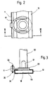
- This upright belt (11) is, as will be explained with reference to FIGS. 2 and 3, provided with drivers (17) which are arranged at regular intervals.
- the drivers (17), which are fork-shaped in the exemplary embodiment, are each assigned to a plate (18).
- the plates (18) have a disk-shaped base plate (19) on which a pin (21) is attached with the interposition of a collar (20). Empty bobbin tubes (22) or full spinning bobbins (23) with their bobbin tubes can be plugged onto these pins (21).
- the plates (18) are guided in a U-shaped profile (24) which forms a U-shaped guide track (12) running around the area of the spinning positions of the ring spinning machine (10).
- the fork-shaped carriers (17) grip the collars (20) of the plates (18) with their fork tines, so that they are positioned in the area of the ring spinning machine (10) according to the distance between the carriers (17).
- the endless belt (11) is guided in the vertical and horizontal directions. In the exemplary embodiment, this guidance takes place by means of guide profiles (25, 26) which surround the band (11) on the lower and upper edge.
- devices (15) for discharging plates (18) and devices (16) for inserting plates (18) adjoin the U-shaped guideway (12).
- These devices (15, 16) can, for example, be continuations of the profile of the guideway (12).
- short conveyor belts are provided in the area of the devices (15, 16), through which the plates can be taken along and actively transported.
- a storage device (14) adjoins the devices (15, 16) for introducing and discharging them, which takes over plates (18) with full spinning bobbins from the ring spinning machine (10) via the device (15) for discharging and plates (18) emits empty bobbin tubes (22) to the ring spinning machine (10) via the device (16) for introducing them.
- the storage device (14) serves as an intermediate store for the full spinning bobbins (23) which are transported to a winding machine by means of the storage device (14). There the full spinning bobbins (23) are delivered to the winding machine together with the plates (18), which in turn then delivers plates with empty bobbin tubes (22) to the storage device (14) via a device corresponding to the device (15) for discharging.
- the storage device (14) then brings the plates (18) with the empty bobbin tubes back to the ring spinning machine (10).
- the storage device (14) has a frame which can be moved on wheels (30). At least one of the impellers (30) expediently contains a drive. At least two of the wheels (30) are also steerable.
- the frame frame is provided on several floors with slide guides (31) for receiving C-shaped guides (32).
- the guides (32) can be moved parallel to one another in the horizontal direction on the sliding guides (31).
- a receiving station (27) and a delivery station (29) are arranged on both sides of the slide guides (31) forming the storage stations (28).
- the receiving station (27) and the delivery station (29) are arranged at such a distance from one another that, when the storage device (14) is delivered to the ring spinning machine (10), it is simultaneously with the device (15) for discharging and the device (16 ) work together to inject, ie are delivered to them.
- the receiving station (27) contains a base plate (33) which is adjustable in height.
- a threaded spindle (34) is provided, which is driven by an electric motor (35).
- the base plate (33) is provided with a nut guided on the threaded spindle (34) so that the base plate (33) can be adjusted in height.
- the guide (32) on the base plate (33) is filled with plates (18) carrying full spinning bobbins (23)
- the level of the sliding guide (31) to which the guide (32) with the full spinning bobbins (23 ) should be delivered.
- the guide (32) with the full spinning bobbins is then pushed laterally onto the corresponding sliding guide (31) by pneumatic cylinders (36).
- all of the guides (32) located on the relevant slide guide (31) are laterally shifted by one position. Since all floors of the storage stations (28) were equipped with guides (32) which contained plates (18) with empty spools, a guide (32) with plates (18) with empty spool sleeves on the receiving station (27 ) on the opposite side to the delivery station (29).
- the delivery station (29) has a structure that is comparable to the structure of the receiving station (27). It contains a base plate (37) which can be adjusted in height by means of a threaded spindle (39) driven by an electric motor (38). The base plate (37) of the delivery station (29) is adjusted in height parallel to the base plate (33) of the receiving station (27). The guide (32) with empty coil sleeves (22), which is delivered at the end of the sliding guide (31) facing it, is pushed onto the base plate (37). The receiving station (27) and the delivery station (29) then move back into their positions assigned to the spinning machine, i.e. to the level of the facilities (15, 16). The delivery station (29) has a transport device with which the plates (18) with the empty bobbin tubes can be delivered in this position.
- the transport device contains a belt (40) which can be moved parallel to the guide (32) received by the base plate (37) and to which a drive motor (41) is assigned.
- Carriers (42) are attached to the belt (40) and can be designed, for example, in accordance with the embodiment according to FIG. 2.
- This band (40) is also placed upright and guided around deflection elements with vertical axes.
- the empty guide (32) is transferred to an additional sliding guide (31), which is located under the storage stations (28) and which serves as a maneuvering level.
- the empty guide (32) is pushed out of the delivery station (29) by a pneumatic cylinder (42) assigned to the maneuvering level, which grips the guide (32) located in the delivery station (29) and pulls on the sliding guide (31) of the maneuvering level.
- An empty guide (32) is transferred to the base plate (33) on the side of the receiving station (27). The work cycle can then start again.
Landscapes
- Engineering & Computer Science (AREA)
- Mechanical Engineering (AREA)
- Textile Engineering (AREA)
- Spinning Or Twisting Of Yarns (AREA)
- Replacing, Conveying, And Pick-Finding For Filamentary Materials (AREA)
Applications Claiming Priority (2)
| Application Number | Priority Date | Filing Date | Title |
|---|---|---|---|
| DE19893907596 DE3907596A1 (de) | 1989-03-09 | 1989-03-09 | Vorrichtung zum bereitstellen von leeren spulenhuelsen und zum abtransportieren von spinnspulen an einer ringspinnmaschine |
| DE3907596 | 1989-03-09 |
Publications (2)
| Publication Number | Publication Date |
|---|---|
| EP0386437A2 true EP0386437A2 (fr) | 1990-09-12 |
| EP0386437A3 EP0386437A3 (fr) | 1991-07-24 |
Family
ID=6375905
Family Applications (1)
| Application Number | Title | Priority Date | Filing Date |
|---|---|---|---|
| EP19900101656 Withdrawn EP0386437A3 (fr) | 1989-03-09 | 1990-01-27 | Dispositif pour mettre en place des tubes de bobines et pour transporter des bobines à un métier à filer à anneaux |
Country Status (3)
| Country | Link |
|---|---|
| EP (1) | EP0386437A3 (fr) |
| JP (1) | JPH02277833A (fr) |
| DE (1) | DE3907596A1 (fr) |
Family Cites Families (8)
| Publication number | Priority date | Publication date | Assignee | Title |
|---|---|---|---|---|
| GB1170660A (en) * | 1967-07-01 | 1969-11-12 | Giddings & Lewis Fraser Ltd | Magazine for Supplying Bobbins to a Winding Machine |
| LU60529A1 (fr) * | 1970-03-16 | 1971-11-08 | ||
| IT1058677B (it) * | 1976-03-23 | 1982-05-10 | Edera Off Mec Tessili | Dispositivo per il carocamento dei tubetti di raccolta del filato su fronti di fusi di filatoi e ritorcitoi |
| DE2656811C3 (de) * | 1976-12-06 | 1979-10-25 | Toray Industries, Inc., Tokio | Verfahren und Vorrichtung zum Transportieren einer Gruppe von Hülsen bzw. Spulen zu und von einer Spulmaschine |
| JPS6194977A (ja) * | 1984-10-16 | 1986-05-13 | Murata Mach Ltd | パツケ−ジ格納装置 |
| DE3712027A1 (de) * | 1986-04-11 | 1987-10-22 | Toyoda Automatic Loom Works | Verfahren und vorrichtung zum transportieren von vollen spulen und leeren spulenkernen bei einer textilmaschine |
| DE3812342C2 (de) * | 1988-04-14 | 1994-08-11 | Zinser Textilmaschinen Gmbh | Transportvorrichtung zum Bereitstellen von leeren Spulenhülsen und zum Abtransport von vollen Spinnspulen an einer doppelseitigen Spinnmaschine |
| EP0344507B1 (fr) * | 1988-05-31 | 1995-10-18 | Maschinenfabrik Rieter Ag | Système de transport entre des machines textiles, en particulier entre des continus à filer à anneaux et des machines de bobinage |
-
1989
- 1989-03-09 DE DE19893907596 patent/DE3907596A1/de not_active Withdrawn
-
1990
- 1990-01-27 EP EP19900101656 patent/EP0386437A3/fr not_active Withdrawn
- 1990-03-07 JP JP5390690A patent/JPH02277833A/ja active Pending
Also Published As
| Publication number | Publication date |
|---|---|
| JPH02277833A (ja) | 1990-11-14 |
| EP0386437A3 (fr) | 1991-07-24 |
| DE3907596A1 (de) | 1990-09-13 |
Similar Documents
| Publication | Publication Date | Title |
|---|---|---|
| EP0709501B1 (fr) | Procédé pour remplacer des pots entre un chariot de transport pour pots plats et un métier à filer à bout libre et chariot de transport pour la mise en oeuvre de ce procédé | |
| DE3431790C2 (fr) | ||
| DE3906718A1 (de) | Transport- und handhabungssystem fuer vielstellen-textilmaschinen insbesondere zwirnmaschinen | |
| EP0454979A2 (fr) | Dispositif pour transporter des bobines | |
| CH662586A5 (de) | Spinnanlage zur herstellung von garn aus vorgarn. | |
| DE3518906A1 (de) | Kopstransportvorrichtung | |
| DE3712027C2 (fr) | ||
| DE3831498C2 (de) | Transportvorrichtung für Kopse | |
| CH648784A5 (de) | Vorrichtung zum zu- und wegfuehren von statoren in kombination mit be- und entladeeinrichtungen bei parallelgeschalteten statorwickelmaschinen. | |
| DE2410408C2 (de) | Vorrichtung zum Auswechseln voller Spulen gegen leere Spulenkörper bei Steck- bzw. Zwirnmaschinen | |
| DE3630670A1 (de) | Spulenfoerdereinrichtung zum transportieren von spinnspulen | |
| DE4338552A1 (de) | Kreuzspulen herstellende Textilmaschine mit einer Vielzahl von in Reihe angeordneten Spulstellen | |
| DE2159860A1 (de) | Verfahren und Vorrichtung zum Ersatz von Garnpaketen eines nicht-gestreckten Garns, das in einer Ziehvorrichtung gestreckt werden soll | |
| DE3513003A1 (de) | Verfahren und vorrichtung zum transport und zur lagerung von spulen, insbesondere zur entsorgung von spinnautomaten oder dergleichen | |
| DE4015938A1 (de) | Spinnereianlage | |
| DE3440598A1 (de) | Spinnmaschine mit einer vielzahl nebeneinander angeordneter spinnstellen | |
| DE19621151B4 (de) | Vorrichtung zum Transportieren von Garnspulen | |
| CH689920A5 (de) | Vorrichtung zum Ent- und Versorgen einer Kreuzspulen herstellenden Maschine. | |
| DE3942492C2 (de) | Palettiervorrichtung für Spulen | |
| DE3877305T2 (de) | Vorrichtung an einer vorspinnmaschine zum automatischen auswechseln von vollen vorgarnspulen gegen spulenhuelsen, auf die das vorgarn aufgewunden wird. | |
| DE3606612A1 (de) | Verfahren und vorrichtung zum selbsttaetigen wechseln von auslaufenden vorgarnspulen an einer spinnmaschine | |
| DE3918877C2 (de) | Transportvorrichtung zum Bereitstellen von Spulenhülsen an den Spinnstellen und zum Abtransportieren von Spinnspulen von den Spinnstellen einer doppelseitigen Spinnmaschine | |
| EP0628648B1 (fr) | Dispositif pour garnir les broches d'un cantre | |
| DE102019110294A1 (de) | Hülsenspeicher- und -transporteinrichtung für eine Kreuzspulen herstellende Textilmaschine | |
| DE68909831T2 (de) | Verfahren zum Transport von Vorgarnspulen, bei dem das Vorgarn vorher in eine bestimmte Lage gebracht wurde. |
Legal Events
| Date | Code | Title | Description |
|---|---|---|---|
| PUAI | Public reference made under article 153(3) epc to a published international application that has entered the european phase |
Free format text: ORIGINAL CODE: 0009012 |
|
| AK | Designated contracting states |
Kind code of ref document: A2 Designated state(s): CH DE FR IT LI |
|
| 17P | Request for examination filed |
Effective date: 19901212 |
|
| PUAL | Search report despatched |
Free format text: ORIGINAL CODE: 0009013 |
|
| AK | Designated contracting states |
Kind code of ref document: A3 Designated state(s): CH DE FR IT LI |
|
| STAA | Information on the status of an ep patent application or granted ep patent |
Free format text: STATUS: THE APPLICATION IS DEEMED TO BE WITHDRAWN |
|
| 18D | Application deemed to be withdrawn |
Effective date: 19920125 |