EP0386531A2 - Plieuse - Google Patents
Plieuse Download PDFInfo
- Publication number
- EP0386531A2 EP0386531A2 EP90103371A EP90103371A EP0386531A2 EP 0386531 A2 EP0386531 A2 EP 0386531A2 EP 90103371 A EP90103371 A EP 90103371A EP 90103371 A EP90103371 A EP 90103371A EP 0386531 A2 EP0386531 A2 EP 0386531A2
- Authority
- EP
- European Patent Office
- Prior art keywords
- cylinder
- folding
- radial direction
- strips
- sections
- Prior art date
- Legal status (The legal status is an assumption and is not a legal conclusion. Google has not performed a legal analysis and makes no representation as to the accuracy of the status listed.)
- Granted
Links
Images


Classifications
-
- B—PERFORMING OPERATIONS; TRANSPORTING
- B65—CONVEYING; PACKING; STORING; HANDLING THIN OR FILAMENTARY MATERIAL
- B65H—HANDLING THIN OR FILAMENTARY MATERIAL, e.g. SHEETS, WEBS, CABLES
- B65H45/00—Folding thin material
- B65H45/12—Folding articles or webs with application of pressure to define or form crease lines
- B65H45/16—Rotary folders
- B65H45/162—Rotary folders with folding jaw cylinders
- B65H45/166—Rotary folders with folding jaw cylinders having an adjustable circumference
-
- B—PERFORMING OPERATIONS; TRANSPORTING
- B41—PRINTING; LINING MACHINES; TYPEWRITERS; STAMPS
- B41F—PRINTING MACHINES OR PRESSES
- B41F13/00—Common details of rotary presses or machines
- B41F13/54—Auxiliary folding, cutting, collecting or depositing of sheets or webs
- B41F13/56—Folding or cutting
- B41F13/62—Folding-cylinders or drums
Definitions
- the invention relates to a folding apparatus with at least two folding cylinders provided with interacting folding tools in the form of folding knives or folding flaps.
- the folding cylinders are placed against one another while maintaining a fixed gap through which the products to be manufactured must pass.
- the clear width of the gap is adapted to the product thickness and usually in such a way that there is a slight undersize compared to the product thickness, which is compensated for by the elasticity of an elastic cylinder support. This only leads to a certain product thickness satisfactory results.
- With a smaller product thickness there is no reliable contact on the cylinder surface.
- the greater product thickness results in a large bulge due to strong pressure in the area of the elastic support, which can lead to a displacement of the products.
- very great difficulties can arise here.
- At least one folding cylinder has circumferential sections which are adjustable in the radial direction at least in some areas.
- the measures according to the invention therefore enable the production of products with very different thicknesses and nevertheless guarantee the same production accuracy and product protection in every case.
- the measures according to the invention thus enable a not inconsiderable broadening of the area of use of a generic folding apparatus and thus result in an overall increase in economy.
- the folding cylinder provided with folding jaws can expediently have circumferential sections which are adjustable in the radial direction, since the length of the products resting on the folding jaw cylinder is shortened to half the length of the section as a result of the folding process. It is therefore sufficient if the peripheral area between the successive folding members is divided into two sections, of which only the section following the adjacent folding member is adjustable in the radial direction and the other is fixed.
- a further expedient measure can consist in the fact that the sections which can be adjusted in the radial direction have a spacing which is arranged next to one another and can be exhibited jointly in the radial direction and which are preferably provided with an elastic covering. This simplifies the structural design, since the strips can simply be arranged to be retractable and extendable. For this purpose, these can expediently be pivoted about a pivot axis parallel to the cylinder axis and provided in the area of the leading strip end.
- the strips can be slidably and tiltably received on a respective cylinder-fixed pin which is encompassed by a return spring and rest on the one hand on a cylinder-side support surface and on the other hand on an adjusting device provided on the cylinder.
- the actuating device can simply have an eccentric shaft which extends parallel to the cylinder parallel to the associated strips and which can be rotated by means of a rotating device and can be fixed by means of a clamping device, which ensures a simple and clear structure and a high level of user friendliness.
- all the eccentric shafts provided on a cylinder can be provided with side drive wheels, the drive wheels provided in the area of a cylinder end face being able to engage a common adjusting ring which is coaxial with the cylinder axis, which advantageously enables all eccentric shafts to be adjusted jointly .
- the structure and mode of operation of folders are known per se.
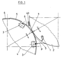
- the centerpiece of a folder is a transverse folder of the type on which the figure is based.
- This comprises a folder knife cylinder 2 provided with folder blades 1 and a folder cylinder 4 cooperating with folder blades 1.
- the two cylinders 2, 4 are driven in such a way that they meet at the same speed
- a gap s is provided between the two cylinders 2, 4, the inside width of which corresponds to the thickness of the unfolded product P or has a slight undersize, so that the product P passing through the gap s is reliably pressed against the surface of the folding knife cylinder 2.
- the clear width of the gap s can be adjusted.
- the circumferential areas between the successive folding flaps 3 are each divided into two sections 5, 6, of which the leading in the direction of rotation Section 5, that is, the section 5 adjacent to the folding flap 3 advancing in the direction of rotation can be adjusted at least with its rear end in the radial direction. This results in a change in the diameter of the folding jaw cylinder in the region of the peripheral sections 5, which prevents the gap s from being too large or too small.
- the adjustable circumferential sections 5 are formed by curved strips 7, which are uniformly distributed over the cylinder width and are arranged next to one another at a distance, which are provided with an elastic covering 8 and which can be opened together in the radial direction.
- strips 9, such as their covering 8, which are made of elastic material can be provided in the extension of the strips 7.
- the spaced-apart strips 7 are received in assigned circumferential slots 10 and can be extended or retracted from these. In the retracted state, the circumferential contour indicated in FIG. 2 results with dashed lines, which merges practically steplessly into the circumferential contour of the strips 9 which are fixedly arranged on the cylinder circumference.
- the strips 7 are pivoted out radially with their rear end in the direction of rotation, so that there is a step with respect to the adjacent, fixed strips 9.
- the resulting increase in diameter of the jaw cylinder 4 enables reliable pressing against the surface of the folder cylinder 2 even in the manufacture of very thin products.
- the strips 7 are swung out so far that the minimum gap width of the gap s when the rear ends of the strips 7 pass the adjacent folding blade cylinder 2 has an undersize of 0.5 mm compared to the product thickness, which is absorbed by deformation of the elastic strips 8.
- the strips 7, as can be seen in FIG. 2, are adjustable in the radial direction and can be tilted on a respectively assigned radial pin 11 arranged in a cylinder-fixed manner.
- the strips 7 are provided with a bracket 12 which is penetrated by the respectively assigned radial pin 11 and which is gripped behind by a chamber-shaped recess 13 into which the end of the respectively assigned radial pin 11 which carries a head 14 projects.
- the yoke 12 is provided with a bore 5 which is penetrated by the shaft of the associated radial pin 11 and which is oversized with respect to the shaft diameter, so that the respective strip 7 can tilt.
- the end of the radial pin 11 protruding into the recess 13 is encompassed by a plate spring assembly 16 which bears on the one hand on the head 14 and on the other hand on the yoke 12 which engages under the head 14.
- the strips 7 are each provided with a support foot 17 or 18.
- the front support leg 17 stands on a cylinder-side support surface 19.
- the rear support foot 18 bears against an eccentric shaft 20 which is parallel to the cylinder axis and which can be rotated in order to pivot out the strips 7 each forming an adjustable peripheral section 5.
- the plate spring 16 is compressed. This works demented speaking as a return spring.
- the eccentric shaft 20 which is parallel to the cylinder, passes through the entire cylinder width in the case of single-width cylinders, so that all strips 7 of an adjustable peripheral section 5, which are uniformly distributed over the cylinder width, can be adjusted together.
- the eccentric shaft 20, as can best be seen in FIG. 3, is received with eccentric collars 21 on roller bearings 22 which are mounted in an associated cylinder bore 23 close to the circumference.
- the eccentric shaft 20 is provided with a protruding square 24 in the region of a cylinder end face, to which a rotary key can be attached.
- the square 24 protrudes over a collar 25 serving as an axial bearing, which rests against the cylinder end face and which can be clamped by means of a clamping claw 26 to secure the set position.
- the collar 25 is designed as a scale carrier provided with a scale 27, which can cooperate with a marking provided on the cylinder side, for example in the form of a notch.
- the folding jaw cylinder 4 is provided with a plurality of folding jaws 3 on the circumference and accordingly with a plurality of adjustable circumferential sections 5, an actuating device assigned to all eccentric shafts can be provided to simplify the operation.
- the eccentric shafts 20, as can best be seen from FIG. 4 can each be provided with a lateral drive wheel 28, wherein all drive wheels 28 are in engagement with a common adjusting ring 29 arranged coaxially to the cylinder axis.
- this is provided with peripheral toothed strips 30, in each of which an associated drive wheel 28 engages.
- the toothed strips 30 are offset from one another by circumferential recesses 31, into which cassettes provided on the cylinder side engage to accommodate the folding jaws 3.
- the adjusting ring 29 arranged in the area of a cylinder end face is received on pins 32 on the cylinder side which engage in assigned arc slots 33. At least one of the pins 32 is designed as a clamping screw 32a, by means of which the adjusting ring 29 can be locked.
- the adjusting ring 29 can be turned by hand.
- the adjusting ring 29 is provided with a toothing 34 provided in the region of its inner circumference, into which engages an adjusting wheel 35 which is mounted in the region of the cylinder end face and which can be provided with a hexagon 36 for attaching a rotary key.
- FIG. 5 This is a double-width jaw cylinder with two cylinder sections 38a, b which can be operated next to one another on a common axis 37 and can be operated independently of one another.
- the strips 7 provided in the region of the two cylinder sections 38a, 38b, which can be retracted and extended in the radial direction, with elastic covering 8 can be operated independently of the strips of the adjacent cylinder section.
- the basic structure corresponds to the structure shown in FIG. 2, the eccentric shaft 20 not passing over the entire cylinder width, but only extending over the associated cylinder section 38a, b.
- the eccentric shafts 20 of the two cylinder sections 38a, b are provided with drive means in the region of the cylinder faces facing away from one another. These correspond to the embodiment according to FIG. 4, with the difference that the adjusting wheel 35 meshing with the adjusting ring 29 is driven by a respectively assigned drive motor 39, which is arranged here inside the cylinder or the respective cylinder section and attached to the relevant end wall from the inside is.
- peripheral portions 6 can tip out in the radial direction only with their rear end in the direction of rotation ensures that only the rear end of the products p, after being provided at the inlet to the gap between the cylinders 2, 4, in FIG 40 indicated guide means, such as brushes, tapes, etc. is no longer guided, pressed against the cylinders 2 and can thus be guided.
- guide means such as brushes, tapes, etc.
- the limitation of the contact pressure to the rear end of the product ensures that the flexing work to be taken up by the sections 6 remains limited and that the products are not damaged, such as a marking, etc.
Landscapes
- Engineering & Computer Science (AREA)
- Mechanical Engineering (AREA)
- Folding Of Thin Sheet-Like Materials, Special Discharging Devices, And Others (AREA)
Applications Claiming Priority (2)
| Application Number | Priority Date | Filing Date | Title |
|---|---|---|---|
| DE3906975 | 1989-03-04 | ||
| DE3906975A DE3906975A1 (de) | 1989-03-04 | 1989-03-04 | Falzapparat |
Publications (3)
| Publication Number | Publication Date |
|---|---|
| EP0386531A2 true EP0386531A2 (fr) | 1990-09-12 |
| EP0386531A3 EP0386531A3 (fr) | 1991-04-10 |
| EP0386531B1 EP0386531B1 (fr) | 1994-06-01 |
Family
ID=6375534
Family Applications (1)
| Application Number | Title | Priority Date | Filing Date |
|---|---|---|---|
| EP90103371A Expired - Lifetime EP0386531B1 (fr) | 1989-03-04 | 1990-02-22 | Plieuse |
Country Status (4)
| Country | Link |
|---|---|
| US (1) | US5039076A (fr) |
| EP (1) | EP0386531B1 (fr) |
| JP (1) | JP2788321B2 (fr) |
| DE (2) | DE3906975A1 (fr) |
Cited By (3)
| Publication number | Priority date | Publication date | Assignee | Title |
|---|---|---|---|---|
| DE4234307A1 (de) * | 1992-10-12 | 1994-04-14 | Heidelberger Druckmasch Ag | Einrichtung zur störungsfreien Produktförderung in Falzapparaten |
| EP1074500A1 (fr) * | 1999-08-05 | 2001-02-07 | Heidelberger Druckmaschinen Aktiengesellschaft | Cylindre de transport de produits d'imprimerie d'un appareil de pliage |
| EP3363634A1 (fr) * | 2017-02-21 | 2018-08-22 | manroland web systems GmbH | Élément rapporté pour un cylindre de pliage à mâchoires et procédé de fabrication d'un élément rapporté d'un cylindre de pliage à mâchoires |
Families Citing this family (19)
| Publication number | Priority date | Publication date | Assignee | Title |
|---|---|---|---|---|
| DE4041613A1 (de) * | 1990-02-19 | 1991-08-22 | Frankenthal Ag Albert | Falzapparat |
| EP0576810B1 (fr) * | 1992-05-29 | 1996-09-18 | Heidelberger Druckmaschinen Aktiengesellschaft | Installation pour aider à transporter d'une façon controlée des exemplaires dans la plieuse de machines d'impression rotatives |
| DE4344622A1 (de) * | 1993-12-24 | 1995-06-29 | Koenig & Bauer Ag | Räderfalzapparat für eine Rotationsdruckmaschine |
| DE29502957U1 (de) * | 1995-02-22 | 1995-04-06 | MAN Roland Druckmaschinen AG, 63075 Offenbach | Zylinder in einem Falzwerk mit vertellbarem Durchmesser |
| DE19516443A1 (de) * | 1995-05-04 | 1996-11-07 | Wifag Maschf | Einzeln angetriebener Falzapparat für eine Rotationsdruckmaschine |
| US6110093A (en) * | 1998-07-06 | 2000-08-29 | Heidelberger Druckmaschinen Ag | Variable diameter roller |
| US6250622B1 (en) * | 1999-05-20 | 2001-06-26 | Heidelberger Druckmaschinen Aktiengesellschaft | Cylinder assembly for a folding apparatus of a rotary printing press |
| JP3056484B1 (ja) | 1999-05-21 | 2000-06-26 | 株式会社東京機械製作所 | 折胴の外径調節装置 |
| US7338425B1 (en) * | 2000-01-12 | 2008-03-04 | Goss International Americas, Inc. | Variable length cutting device |
| US6923752B1 (en) | 2000-04-18 | 2005-08-02 | Goss International Americas, Inc. | Folding cylinder with expansion segment |
| US6761678B1 (en) * | 2000-05-15 | 2004-07-13 | Heidelberger Druckmaschinen Ag | Folding cylinder with expansion plate |
| JP3392110B2 (ja) | 2000-08-09 | 2003-03-31 | 株式会社東京機械製作所 | 折畳装置の回転胴 |
| DE10102808A1 (de) * | 2001-01-23 | 2002-07-25 | Heidelberger Druckmasch Ag | Selbsttätig schliessendes Flächenelement am Umfang von Zylindern |
| DE10148503C5 (de) | 2001-10-01 | 2008-01-31 | Koenig & Bauer Aktiengesellschaft | Falzapparat mit umfangsverstellbarem Zylinder |
| DE10148504C1 (de) * | 2001-10-01 | 2003-01-23 | Koenig & Bauer Ag | Umfangsverstellbarer Zylinder |
| DE10311393B4 (de) * | 2003-03-13 | 2007-07-19 | Koenig & Bauer Aktiengesellschaft | Falzzylinder mit an seiner Mantelfläche verstellbaren Elementen |
| DE102004020304B4 (de) * | 2004-04-26 | 2007-11-29 | Koenig & Bauer Aktiengesellschaft | Zylinder für die Bearbeitung von Flachmaterial |
| US7896795B2 (en) * | 2005-10-25 | 2011-03-01 | Goss International Americas, Inc. | Folder with signature support |
| DE102022207528A1 (de) | 2022-07-22 | 2024-01-25 | Bhs Corrugated Maschinen- Und Anlagenbau Gmbh | Gegenzylinder-Anordnung |
Family Cites Families (15)
| Publication number | Priority date | Publication date | Assignee | Title |
|---|---|---|---|---|
| DE1074057B (fr) * | 1960-01-28 | |||
| US1499106A (en) * | 1923-03-28 | 1924-06-24 | Hoe & Co R | Folding cylinder |
| US1821713A (en) * | 1930-01-17 | 1931-09-01 | Scott Isabella | Paper handling device |
| US1865696A (en) * | 1930-09-19 | 1932-07-05 | Wood Newspaper Corp | Adjustable folding cylinder |
| DE1132564B (de) * | 1961-08-12 | 1962-07-05 | Albert Schnellpressen | Nuten- und Falzmesserzylinder an Punkturfalzapparaten |
| CH417646A (de) * | 1963-05-24 | 1966-07-31 | Winkler Fallert & Co Maschf | Falzmesser- und Sammelzylinder an Punkturfalzapparaten |
| US3477709A (en) * | 1967-03-20 | 1969-11-11 | Wood Industries Inc | Folding cylinder having adjustable band construction |
| DE2011661B1 (de) * | 1970-03-12 | 1971-07-15 | Maschinenfabrik Augsburg Nuernberg Ag | Falzmesszylinder für Rotationsdruckma schinen |
| DE2040494B2 (de) * | 1970-08-14 | 1971-07-29 | Maschf Augsburg Nuernberg Ag | Sammel und falzzylinder fuer falzapparate von rotations druckmaschinen |
| DE2309919A1 (de) * | 1973-02-28 | 1974-09-05 | Frankenthal Ag Albert | Nuten- und falzmesserzylinder an falzapparaten von rotationsdruckmaschinen |
| DE2530365C3 (de) * | 1975-07-08 | 1979-05-17 | Maschinenfabrik Augsburg-Nuernberg Ag, 8900 Augsburg | Einrichtung zur Durchmesserverstellung eines Zylinders |
| DE2656267C3 (de) * | 1976-12-11 | 1980-05-08 | Koenig & Bauer Ag, 8700 Wuerzburg | Falzapparat für Rollenrotationsdruckmaschinen |
| US4437855A (en) * | 1980-03-24 | 1984-03-20 | Publishers Equipment Corporation | Reduction of cutoff length for folding mechanisms |
| DE3217169C2 (de) * | 1982-05-07 | 1985-08-08 | Koenig & Bauer AG, 8700 Würzburg | Falzmesserzylinder |
| JP2538925B2 (ja) * | 1987-06-24 | 1996-10-02 | 三菱重工業株式会社 | 輪転機における折胴の胴径調整装置 |
-
1989
- 1989-03-04 DE DE3906975A patent/DE3906975A1/de not_active Withdrawn
-
1990
- 1990-02-05 US US07/475,189 patent/US5039076A/en not_active Expired - Lifetime
- 1990-02-22 DE DE59005857T patent/DE59005857D1/de not_active Expired - Fee Related
- 1990-02-22 EP EP90103371A patent/EP0386531B1/fr not_active Expired - Lifetime
- 1990-03-02 JP JP2051621A patent/JP2788321B2/ja not_active Expired - Fee Related
Cited By (3)
| Publication number | Priority date | Publication date | Assignee | Title |
|---|---|---|---|---|
| DE4234307A1 (de) * | 1992-10-12 | 1994-04-14 | Heidelberger Druckmasch Ag | Einrichtung zur störungsfreien Produktförderung in Falzapparaten |
| EP1074500A1 (fr) * | 1999-08-05 | 2001-02-07 | Heidelberger Druckmaschinen Aktiengesellschaft | Cylindre de transport de produits d'imprimerie d'un appareil de pliage |
| EP3363634A1 (fr) * | 2017-02-21 | 2018-08-22 | manroland web systems GmbH | Élément rapporté pour un cylindre de pliage à mâchoires et procédé de fabrication d'un élément rapporté d'un cylindre de pliage à mâchoires |
Also Published As
| Publication number | Publication date |
|---|---|
| DE3906975A1 (de) | 1990-09-06 |
| JP2788321B2 (ja) | 1998-08-20 |
| EP0386531B1 (fr) | 1994-06-01 |
| DE59005857D1 (de) | 1994-07-07 |
| EP0386531A3 (fr) | 1991-04-10 |
| US5039076A (en) | 1991-08-13 |
| JPH02270763A (ja) | 1990-11-05 |
Similar Documents
| Publication | Publication Date | Title |
|---|---|---|
| EP0386531A2 (fr) | Plieuse | |
| DE69215206T2 (de) | Lünette mit einer internen Einstellungsvorrichtung für die Zentrumachse | |
| DE68914769T2 (de) | Vorrichtung zum Regeln der Schneidelänge. | |
| DE2755361C2 (de) | Falzklappenzylinder für Rotationsfalzwerk | |
| DE2602262B2 (de) | Vorrichtung für das Abkanten von topfförmigen, metallenen Werkstücken, insbesondere Dosenriimpfen u.dgl | |
| EP1551214A1 (fr) | Barre de coupe | |
| DE2827983A1 (de) | Schneidmaschine mit rotierendem messer | |
| DE2206935C3 (de) | Werkzeug zum rückwärtigen Ansenken des Randes von Durchgangsbohrungen | |
| DE2307266A1 (de) | Schneidwerkswellen-vorrichtung in einer pelletisiermaschine fuer kunststoffe | |
| DE3234215C2 (fr) | ||
| DE60206315T2 (de) | Vorrichtung zur Montage und Demontage der Tücher einer Gegenwalze in einer Rotationsstanzmaschine | |
| DE3404098C1 (de) | Mikrotom mit einer Objektrueckzugeinrichtung | |
| DE3049171A1 (de) | Horizontalbandsaegemaschine | |
| DE2820259B2 (de) | Quetsch-Zuspitzmaschine zur Formung des Führungsendes von Schrauben oder ähnlichen Befestigungsmitteln | |
| EP0348806A2 (fr) | Dispositif pour accoupler la broche d'une bobine ou similaire avec un arbre d'entraînement | |
| DE3026162C2 (de) | Vorrichtung zum Festspannen eines Holzklotzes zum exzentrischen oder Stay-log-Schälen | |
| EP2296857B1 (fr) | Granulateur de joncs à espace de coupe réglable et procédé de réglage pour l'espace de coupe | |
| DE2948719C2 (de) | Messerwalzen-Maschine zur Bearbeitung von Häuten und Fellen | |
| DE3308219C2 (de) | Maschine zum Profilieren von Blechen für die Herstellung von Falzen | |
| DE9411121U1 (de) | Greiferzylinder in einem Falzapparat | |
| DE2648777C2 (de) | Abrichtvorrichtung für Profilschleifscheiben | |
| DE2614419B2 (de) | Sägenschärfmaschine | |
| EP0102014B1 (fr) | Cage de laminoir pour le laminage de feuillard à largeur différente | |
| DE69205473T2 (de) | Vorrichtung zum Formen einer Einschnürung an der offener Seite einer metallen Dosenkörper. | |
| DE2723432A1 (de) | Tischanschlag fuer eine stanzmaschine |
Legal Events
| Date | Code | Title | Description |
|---|---|---|---|
| PUAI | Public reference made under article 153(3) epc to a published international application that has entered the european phase |
Free format text: ORIGINAL CODE: 0009012 |
|
| AK | Designated contracting states |
Kind code of ref document: A2 Designated state(s): CH DE FR GB IT LI SE |
|
| PUAL | Search report despatched |
Free format text: ORIGINAL CODE: 0009013 |
|
| AK | Designated contracting states |
Kind code of ref document: A3 Designated state(s): CH DE FR GB IT LI SE |
|
| 17P | Request for examination filed |
Effective date: 19910423 |
|
| 17Q | First examination report despatched |
Effective date: 19921119 |
|
| GRAA | (expected) grant |
Free format text: ORIGINAL CODE: 0009210 |
|
| AK | Designated contracting states |
Kind code of ref document: B1 Designated state(s): CH DE FR GB IT LI SE |
|
| REF | Corresponds to: |
Ref document number: 59005857 Country of ref document: DE Date of ref document: 19940707 |
|
| ITF | It: translation for a ep patent filed | ||
| GBT | Gb: translation of ep patent filed (gb section 77(6)(a)/1977) |
Effective date: 19940824 |
|
| ET | Fr: translation filed | ||
| EAL | Se: european patent in force in sweden |
Ref document number: 90103371.2 |
|
| PLBE | No opposition filed within time limit |
Free format text: ORIGINAL CODE: 0009261 |
|
| STAA | Information on the status of an ep patent application or granted ep patent |
Free format text: STATUS: NO OPPOSITION FILED WITHIN TIME LIMIT |
|
| 26N | No opposition filed | ||
| REG | Reference to a national code |
Ref country code: GB Ref legal event code: IF02 |
|
| PGFP | Annual fee paid to national office [announced via postgrant information from national office to epo] |
Ref country code: CH Payment date: 20080221 Year of fee payment: 19 |
|
| PGFP | Annual fee paid to national office [announced via postgrant information from national office to epo] |
Ref country code: SE Payment date: 20080219 Year of fee payment: 19 Ref country code: IT Payment date: 20080221 Year of fee payment: 19 Ref country code: GB Payment date: 20080219 Year of fee payment: 19 Ref country code: DE Payment date: 20080311 Year of fee payment: 19 |
|
| PGFP | Annual fee paid to national office [announced via postgrant information from national office to epo] |
Ref country code: FR Payment date: 20080215 Year of fee payment: 19 |
|
| REG | Reference to a national code |
Ref country code: CH Ref legal event code: PL |
|
| EUG | Se: european patent has lapsed | ||
| GBPC | Gb: european patent ceased through non-payment of renewal fee |
Effective date: 20090222 |
|
| PG25 | Lapsed in a contracting state [announced via postgrant information from national office to epo] |
Ref country code: CH Free format text: LAPSE BECAUSE OF NON-PAYMENT OF DUE FEES Effective date: 20090228 Ref country code: LI Free format text: LAPSE BECAUSE OF NON-PAYMENT OF DUE FEES Effective date: 20090228 |
|
| REG | Reference to a national code |
Ref country code: FR Ref legal event code: ST Effective date: 20091030 |
|
| PG25 | Lapsed in a contracting state [announced via postgrant information from national office to epo] |
Ref country code: DE Free format text: LAPSE BECAUSE OF NON-PAYMENT OF DUE FEES Effective date: 20090901 |
|
| PG25 | Lapsed in a contracting state [announced via postgrant information from national office to epo] |
Ref country code: GB Free format text: LAPSE BECAUSE OF NON-PAYMENT OF DUE FEES Effective date: 20090222 Ref country code: FR Free format text: LAPSE BECAUSE OF NON-PAYMENT OF DUE FEES Effective date: 20090302 |
|
| PG25 | Lapsed in a contracting state [announced via postgrant information from national office to epo] |
Ref country code: IT Free format text: LAPSE BECAUSE OF NON-PAYMENT OF DUE FEES Effective date: 20090222 |
|
| PG25 | Lapsed in a contracting state [announced via postgrant information from national office to epo] |
Ref country code: SE Free format text: LAPSE BECAUSE OF NON-PAYMENT OF DUE FEES Effective date: 20090223 |