EP0387052A2 - Magnetooptisches Aufzeichnungsgerät mit Mitteln zur Verzögerung des Eingangssignales zur Verhinderung von Bitverschiebung - Google Patents
Magnetooptisches Aufzeichnungsgerät mit Mitteln zur Verzögerung des Eingangssignales zur Verhinderung von Bitverschiebung Download PDFInfo
- Publication number
- EP0387052A2 EP0387052A2 EP90302466A EP90302466A EP0387052A2 EP 0387052 A2 EP0387052 A2 EP 0387052A2 EP 90302466 A EP90302466 A EP 90302466A EP 90302466 A EP90302466 A EP 90302466A EP 0387052 A2 EP0387052 A2 EP 0387052A2
- Authority
- EP
- European Patent Office
- Prior art keywords
- medium
- light beam
- signal
- magnetic field
- recording
- Prior art date
- Legal status (The legal status is an assumption and is not a legal conclusion. Google has not performed a legal analysis and makes no representation as to the accuracy of the status listed.)
- Granted
Links
- 230000003287 optical effect Effects 0.000 claims abstract description 36
- 230000003111 delayed effect Effects 0.000 claims abstract description 20
- 238000000034 method Methods 0.000 claims description 18
- 230000000694 effects Effects 0.000 claims 2
- 230000005855 radiation Effects 0.000 claims 2
- 230000003313 weakening effect Effects 0.000 claims 1
- 239000004065 semiconductor Substances 0.000 description 14
- 238000010586 diagram Methods 0.000 description 7
- 230000001934 delay Effects 0.000 description 4
- 230000002093 peripheral effect Effects 0.000 description 4
- 230000000875 corresponding effect Effects 0.000 description 3
- 230000012447 hatching Effects 0.000 description 3
- 238000010276 construction Methods 0.000 description 2
- 230000001276 controlling effect Effects 0.000 description 2
- 239000011521 glass Substances 0.000 description 2
- 230000005415 magnetization Effects 0.000 description 2
- 230000000630 rising effect Effects 0.000 description 2
- 239000000758 substrate Substances 0.000 description 2
- ZXVONLUNISGICL-UHFFFAOYSA-N 4,6-dinitro-o-cresol Chemical compound CC1=CC([N+]([O-])=O)=CC([N+]([O-])=O)=C1O ZXVONLUNISGICL-UHFFFAOYSA-N 0.000 description 1
- 230000002596 correlated effect Effects 0.000 description 1
- 238000001514 detection method Methods 0.000 description 1
- 230000004044 response Effects 0.000 description 1
Images






Classifications
-
- G—PHYSICS
- G11—INFORMATION STORAGE
- G11B—INFORMATION STORAGE BASED ON RELATIVE MOVEMENT BETWEEN RECORD CARRIER AND TRANSDUCER
- G11B11/00—Recording on or reproducing from the same record carrier wherein for these two operations the methods are covered by different main groups of groups G11B3/00 - G11B7/00 or by different subgroups of group G11B9/00; Record carriers therefor
- G11B11/10—Recording on or reproducing from the same record carrier wherein for these two operations the methods are covered by different main groups of groups G11B3/00 - G11B7/00 or by different subgroups of group G11B9/00; Record carriers therefor using recording by magnetic means or other means for magnetisation or demagnetisation of a record carrier, e.g. light induced spin magnetisation; Demagnetisation by thermal or stress means in the presence or not of an orienting magnetic field
- G11B11/105—Recording on or reproducing from the same record carrier wherein for these two operations the methods are covered by different main groups of groups G11B3/00 - G11B7/00 or by different subgroups of group G11B9/00; Record carriers therefor using recording by magnetic means or other means for magnetisation or demagnetisation of a record carrier, e.g. light induced spin magnetisation; Demagnetisation by thermal or stress means in the presence or not of an orienting magnetic field using a beam of light or a magnetic field for recording by change of magnetisation and a beam of light for reproducing, i.e. magneto-optical, e.g. light-induced thermomagnetic recording, spin magnetisation recording, Kerr or Faraday effect reproducing
- G11B11/10502—Recording on or reproducing from the same record carrier wherein for these two operations the methods are covered by different main groups of groups G11B3/00 - G11B7/00 or by different subgroups of group G11B9/00; Record carriers therefor using recording by magnetic means or other means for magnetisation or demagnetisation of a record carrier, e.g. light induced spin magnetisation; Demagnetisation by thermal or stress means in the presence or not of an orienting magnetic field using a beam of light or a magnetic field for recording by change of magnetisation and a beam of light for reproducing, i.e. magneto-optical, e.g. light-induced thermomagnetic recording, spin magnetisation recording, Kerr or Faraday effect reproducing characterised by the transducing operation to be executed
- G11B11/10504—Recording
- G11B11/10508—Recording by modulating only the magnetic field at the transducer
-
- G—PHYSICS
- G11—INFORMATION STORAGE
- G11B—INFORMATION STORAGE BASED ON RELATIVE MOVEMENT BETWEEN RECORD CARRIER AND TRANSDUCER
- G11B11/00—Recording on or reproducing from the same record carrier wherein for these two operations the methods are covered by different main groups of groups G11B3/00 - G11B7/00 or by different subgroups of group G11B9/00; Record carriers therefor
- G11B11/10—Recording on or reproducing from the same record carrier wherein for these two operations the methods are covered by different main groups of groups G11B3/00 - G11B7/00 or by different subgroups of group G11B9/00; Record carriers therefor using recording by magnetic means or other means for magnetisation or demagnetisation of a record carrier, e.g. light induced spin magnetisation; Demagnetisation by thermal or stress means in the presence or not of an orienting magnetic field
- G11B11/105—Recording on or reproducing from the same record carrier wherein for these two operations the methods are covered by different main groups of groups G11B3/00 - G11B7/00 or by different subgroups of group G11B9/00; Record carriers therefor using recording by magnetic means or other means for magnetisation or demagnetisation of a record carrier, e.g. light induced spin magnetisation; Demagnetisation by thermal or stress means in the presence or not of an orienting magnetic field using a beam of light or a magnetic field for recording by change of magnetisation and a beam of light for reproducing, i.e. magneto-optical, e.g. light-induced thermomagnetic recording, spin magnetisation recording, Kerr or Faraday effect reproducing
- G11B11/10502—Recording on or reproducing from the same record carrier wherein for these two operations the methods are covered by different main groups of groups G11B3/00 - G11B7/00 or by different subgroups of group G11B9/00; Record carriers therefor using recording by magnetic means or other means for magnetisation or demagnetisation of a record carrier, e.g. light induced spin magnetisation; Demagnetisation by thermal or stress means in the presence or not of an orienting magnetic field using a beam of light or a magnetic field for recording by change of magnetisation and a beam of light for reproducing, i.e. magneto-optical, e.g. light-induced thermomagnetic recording, spin magnetisation recording, Kerr or Faraday effect reproducing characterised by the transducing operation to be executed
- G11B11/1053—Recording on or reproducing from the same record carrier wherein for these two operations the methods are covered by different main groups of groups G11B3/00 - G11B7/00 or by different subgroups of group G11B9/00; Record carriers therefor using recording by magnetic means or other means for magnetisation or demagnetisation of a record carrier, e.g. light induced spin magnetisation; Demagnetisation by thermal or stress means in the presence or not of an orienting magnetic field using a beam of light or a magnetic field for recording by change of magnetisation and a beam of light for reproducing, i.e. magneto-optical, e.g. light-induced thermomagnetic recording, spin magnetisation recording, Kerr or Faraday effect reproducing characterised by the transducing operation to be executed to compensate for the magnetic domain drift or time shift
Definitions
- This invention relates to a magneto-optical recording apparatus for recording signals by applying a magnetic field modulated in conformity with a recording signal to a magneto-optical recording medium while applying a laser beam to the magneto-optical recording medium.
- magneto-optical recording has been drawing attention because of its capability of rewriting information.
- a method of the magneto-optical recording there is known a method of applying a magnetic field modulated in conformity with a recording signal to a magneto-optical recording medium while applying a light beam to the magneto-optical recording medium. This method is called the magnetic field modulation method, and has a feature that signals to be renewed can be overwritten without previously recorded signals being erased in advance.
- FIG. 1 An example of a magneto-optical recording apparatus using the above-described method is schematically shown in Figure 1 of the accompanying drawings.
- the reference numeral 1 designates a magneto-optical disk which is formed by attaching vertically magnetized film 3 to a glass substrate 2. This magneto-optical disk 1 is rotated about the center axis 0 - 0′.
- the reference numeral 4 denotes an optical head for applying a laser light to the vertically magnetized film 3 of the magneto-optical disk 1.
- This optical head 4 is comprised chiefly of a semiconductor laser 5 and a condensing lens 6.
- the optical head 4 is designed to act on the vertically magnetized film 3 so that the laser light may be focused thereon, and to be movable radially of the magneto-optical disk 1.
- the reference numeral 7 desingates an electromagnet disposed so as to be opposed to the optical head 4 relative to the magneto-optical disk 1 and applying a bias magnetic field to the vertically magnetized film 3.
- This electromagnet 7 is designed to move radially of the magneto-optical disk in operative association with the optical head 4.
- An electric current inverted in phase in conformity with a recording signal is supplied from a magnetic field modulation circuit 9 to the coil 8 of the electromagnet 7.
- the magnetic field modulation circuit 9 is operated by a recording signal input from a terminal 10.
- the electromagnet 7 produces a magnetic field shown in (d1) of Figure 2 in synchronism therewith.
- the recording signal is "1”
- a magnetic field of a predetermined intensity +H is produced in a direction with the direction of magnetization of the vertically magnetized film 3 as the upward direction.
- the recording signal is "0”
- a magnetic field of a predetermined intensity -H is produced just in the opposite direction to that when the recording signal is "1".
- the optical head 4 continuously emits a laser light of a predetermined intensity as shown in (c1) of Figure 2 when the recording condition is brought about, and the laser light locally illuminates the vertically magnetized film of the magneto-optical disk 1.
- the temperature of the vertically magnetized film in this irradiated portion rises to the curie point or higher.
- a recording pattern as shown as a model in (e1) of Figure 2 is formed on the vertically magnetized film.
- the white portions and the recording patterns indicated by hatching show the upwardly magnetized state and the downwardly magnetized state, respectively.
- the spot of the light beam has a finite size, and this has led to a problem that the end portion of each bit of the recording pattern suffers from positional deviation relative to the recording signal, i.e., so-called bit shift, as shown in Figure 2.
- bit shift the shape of the recording bit becomes a chevron-like shape as shown in (e1) of Figure 2 and therefore, there has been created a time different t2 between the center of the recording signal and the peak of a signal (f1) reproduced from this recording pattern. This phenomenon will hereinafter be referred to as the peak shift.
- the time t1 to the peak of the reproduction signal (f1) becomes shorter by (t3 - t2) relative to the time t0 from a synchronizing signal reproduced from a prepit formed unevenly on the magneto-optical disk 1 to the center of "1" of the recording signal.
- t3 is the time difference by bit shift
- t2 is the time difference by peak shift.
- an apparatus for recording an input signal on a magneto-optical recording medium comprising means for applying a light beam to said medium, means for delaying said input signal by a time for preventing a bit recorded on the medium from shifting relative to said input signal, means for applying a magnetic field modulated in conformity with said delayed signal to that portion of the medium to which the light beam is applied, and means for moving said medium relative to said light beam.
- provision may be made of means for making the intensity of the magnetic field applied to the medium smaller in the rear portion of each pulse of a recording signal than in the other portion, whereby a recording bit can be prevented from assuming a chevron-like shape, thereby eliminating peak shift.
- Figure 3 is a schematic view showing the construction of a first embodiment of the magneto-optical recording apparatus according to the present invention.
- the reference numeral 11 designates a magneto-optical disk which is formed by attaching vertically magnetized film 13 to a glass substrate 12. A plurality of tracks are formed concentrically or spirally on the disk 11. This magneto-optical disk 11 is rotated about the center axis 0 - 0′ by a spindle motor, not shown.
- the reference numeral 14 denotes an optical head basically comprised of a semiconductor laser 15 and a lens 16. A laser light emitted from the semiconductor laser 15 is condensed by the lens 16 so as to be always focused on the vertically magnetized film 13.
- the optical head 14 is also movable radially of the magneto-optical disk 11.
- the reference numeral 17 designates a bias magnetic field producing head disposed in opposed relationship with the position at which the laser light is condensed by the optical head 14.
- the bias magnetic field producing head 17 comprises an electromagnet including a coil 18.
- the bias magnetic field producing head 17 is driven by a magnetic field modulation circuit 19.
- the reference numeral 20 denotes a delay circuit for delaying an information signal input from a terminal 21.
- the magnetic field modulation circuit 19 is driven in synchronism with the information signal delayed by the delay circuit 20.
- the amount of delay by the delay circuit 20 is a time corresponding to t3 shown in Figure 2 which shows the prior art.
- the bias magnetic field producing head 17 is designed to move radially of the optical disk 11, following the optical head 14.
- a synchronizing signal (a2) indicative of the beginning of an information recording area has been obtained from a prepit prerecorded on the magneto-optical disk 11.
- a recording signal (b2) is input with this synchronizing signal a2 as a reference.
- This recording signal (b2) is input from the terminal 21 to the delay circuit 20, where it is delayed by the time t3 and becomes a delay signal (c2).
- a laser light is emitted from the optical head 14, and as indicated by (d2), continues to be continuously applied onto the magneto-optical disk 11 with such a laser power Pw that will render the temperature of the vertically magnetized film 13 higher than the curie point.
- the magnetic field modulation circuit 19 in response to the delay signal (c2), applies a magnetic field modulated with intensities of ⁇ H shown in (e2) from the bias magnetic field producing head 17 to the disk.
- a pattern schematically shown in (f2) is recorded on the vertically magnetized film 13.
- the white portions and the hatching portions respectively represent that the vertically magnetized film is magnetized upwardly and downwardly.
- a signal reproduced from this recording pattern is such as shown in (g2).
- the reproduction signal assumes a waveform which is not affected by the bit shift as shown in the example of the prior art.
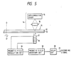
- FIG. 5 is a schematic view showing a second embodiment of the magneto-optical recording apparatus of the present invention.
- the present embodiment differs from the aforedescribed embodiment in that a magnetic field waveform adjusting circuit 30 is provided between the delay circuit 20 and the magnetic field modulation circuit 19.
- this circuit 30 makes the magnetic field intensity in the rear end portion of the recording pulse smaller than that in the other portion. Thereby, the recording pattern is prevented from assuming a chevron-like shape, and in addition to the aforementioned bit shift, peak shift is eliminated.
- a synchronizing signal (a3) is detected from the magneto-optical disk 11
- a recording signal (b3) is input with this synchronizing signal (a3) as a reference.
- This recording signal (b3) is delayed by t3 indicated in Figure 2 by the delay circuit 20, and becomes a delay signal (c3).
- the magnetic field waveform adjusting circuit 30 produces a bias magnetic field of the intensity shown in (e3) from the bias magnetic field producing head 17 through the magnetic field modulation circuit 19. This magnetic field is controlled so that its intensity may become smaller during the time corresponding to the rear portion of the bit in the pulse forming each bit than during the time corresponding to the other portion.
- a laser light of the intensity shown in (d3) is continuously applied from the optical head 14 to the disk 11. Since the intensity of the laser light is thus constant, the width of a recorded bit depends on the intensity of the magnetic field applied.
- the intensity of the magnetic field becomes weak in the rear end portion of the pulse, a bit is formed only in the higher temperature area of the temperature distribution on the vertically magnetized film 3. Accordingly, the pattern of the recorded bit becomes such as schematically shown in (f3) and does not assume a chevron-like shape.
- the white portions and the hatching portions respectively represent that the vertically magnetized film is magnetized upwardly and downwardly.
- a signal reproduced from such a recording pattern is free from bit shift and peak shift, as shown in (g3).
- the temperature of the medium has been constant, but it is conceivable that if this temperature changes, it will affect the amount of bit shift. This will now be described with reference to Figures 7 and 8.
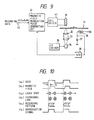
- Figure 9 is a schematic view showing a third embodiment of the present invention which takes the influence of the temperature of the medium upon bit shift into account.
- the reference numeral 31 designates a magneto-optical disk which is a recording medium
- the reference numeral 34 denotes a semiconductor laser unit
- the reference numeral 33 designates a collimator lens for collimating a light beam emitted from the semiconductor laser
- the reference numeral 32 denotes an objective lens for condensing the collimated light beam on the disk 31
- the reference numeral 35 designates a laser driver for driving the semiconductor laser unit 34.
- the reference numeral 36 denotes a thermistor for measuring the temperature of the surroundings of the recording medium
- the reference numeral 37 designates a fixed resistor
- the reference numeral 38 denotes an analog-digital (A/D) converter for converting the signal from the thermister 36 into a digital signal
- the reference numeral 39 designates a magnetic field producing coil
- the reference numeral 40 denotes a driver for the magnetic field producing coil 39
- the reference numeral 41 designates a magnetic field modulation pulse generating circuit
- the reference numeral 42 denotes a terminal to which recording data is input.
- the magneto-optical disk 31 is rotated at a predetermined number of rotations by a spindle motor, not shown.
- a certain set electric current flows from the laser driver 35 to the semiconductor laser unit 34, whereby a predetermined quantity of light is emitted therefrom.
- This emitted light passes through the collimator lens 33 and becomes a parallel light, and is condensed with a certain spot diameter on the disk by the objective lens 32.
- the thermistor 36 installed closely adjacent to the medium assumes a resistance value nearly correlated with the temperature of the medium. Accordingly, when the applied voltage to the thermistor is Vcc, a voltage value obtained by dividing Vcc by the resistance value of the thermistor and the fixed resistor 37 is input to the A/D converter 38.
- the output of the A/D converter 38 is input to the magnetic field modulation pulse generating circuit 41, where the amount of bit shift is calculated in accordance with the measured temperature and further, a delay time for compensating for this bit shift is calculated. Then, the circuit 41 delays the data input from the terminal 42 by the calculated time and sends it to the coil driver 40. In the coil driver 40, an electric current is caused to flow clockwisely or counter-clockwisely to the coil 39 in conformity with the data sent from the circuit 41, whereby the direction of the magnetic field is modulated. That is, in the present embodiment, the delay time of the input signal is lengthened or shortened in accordance with the rise or fall of the temperature of the medium. Thus, it is possible to compensate for the bit shift without being affected by a change in the temperature of the medium.
- Figure 10 schematically shows the manner of recording using the apparatus shown in Figure 9.
- the delay time tp of the magnetic field (b6) with respect to data (a6) is that calculated in the aforedescribed magnetic field modulation pulse generating circuit 41 on the basis of the detected temperature of the medium.
- the reproduction signal (f6) is made always free of time deviation relative to the data (a6).
- the temperature of the environment near the medium has been detected as the temperature of the medium.
- the temperature of the medium may be directly measured as by bringing a thermistor into contact with the medium.
- the variation in the amount of bit shift as described with reference to Figures 7 and 8 is caused not only by a change in the temperature of the medium, but also by a change in the relative speed of the medium and the light beam. This is because any change in the speed varies the energy applied to the unit area of the medium per unit time. For example, where the magneto-optical disk is rotated at a predetermined angular speed, the line speed of the light beam relative to the medium becomes lower when the light beam is on the inner peripheral portion of the disk than when the light beam is on the outer peripheral portion of the disk. Thereupon, the isothermal line of the magnetic film widens as in the case of Figure 8 and the amount of bit shift increases. Accordingly, it is conceivable that if the delay time is set in accord with the outer peripheral portion of the disk, bit shift cannot be completely eliminated on the inner peripheral portion.
- FIG. 11 A fourth embodiment of the present invention which takes the influence of the relative speed of the medium and the light beam as described above into account is shown in the schematic diagram of Figure 11.
- the reference numeral 44 designates a spindle motor for rotating the magneto-optical disk 31
- the reference numeral 43 denotes an optical head carrying the semiconductor laser unit 34, etc. thereon
- the reference numeral 46 designates a head feeding motor for moving the optical head 43 radially of the disk
- the reference numeral 45 denotes a motor control circuit for controlling the head feeding motor 46 and the spindle motor 44.
- the spindle motor 44 revolves under the control of the motor control circuit 45, whereby the disk 31 is rotated at a predetermined number of rotations.
- the address of a desired track on which recording is to be effected is indicated from a host controller, not shown, to the motor control circuit 45.
- the motor control circuit 45 drives the head feeding motor 46 on the basis of this indication, thereby moving the optical head 43 to right beneath the desired track.
- the light emitted from the semiconductor laser unit 34 is condensed by the objective lens 32 and applied to this track.
- the address of the above-mentioned track is input from the motor control circuit to the magnetic field modulation pulse generating circuit 41.
- the circuit 41 finds from this address the line speed of the disk relative to the light beam, and a delay time for compensating for the amount of bit shift conforming to this line speed is calculated.
- the circuit 41 delays the data input from the terminal 42 by the calculated time, and sends a magnetic field modulation pulse based on this delayed data to the coil driver 40.
- the coil driver 40 drives the coil 39 by the pulse sent from the circuit 41, thereby applying a magnetic field modulated in polarity to the disk 31.
- the line speed has been calculated from the address of a desired track, but for example, by mounting an encoder on the optical head, the radial position may be directly detected and the delay time may be calculated by the use of the result of the detection.
- Figure 12 is a schematic diagram showing a fifth embodiment of the present invention.
- the reference numeral 47 designates a laser unit containing therein a semiconductor laser and a photodiode for receiving part of the emitted light of the laser
- the reference numeral 48 denotes a current/voltage (I/V) converter for converting the output current of the photodiode into a voltage
- the reference numeral 49 designates a laser control circuit for controlling the laser driver 35 in accordance with the output of the converter 48.
- the laser control circuit 49 sets the reference value of the output power of the laser by a command from a centralized control circuit 50.
- the centralized control circuit 50 sends the address of a desired track to the motor control circuit 45, and moves the optical head 43 to right beneath a track on which recording is to be effected by the head feeding motor 46. Further, information regarding the temperature of the surroundings of the disk 31 is input to the centralized control circuit 50 through the analog-digital (A/D) converter 38.
- A/D analog-digital
- the magneto-optical disk 31 is rotated at a predetermined number of rotations by the spindle motor 44.
- the optical head 43 is moved to right beneath a desired track in the same manner as in the fourth embodiment, on the basis of the address indicated from the centralized control circuit 50.
- a light of power PomW is emitted from the semiconductor laser in the laser unit 47, and is collimated through the collimator lens 33 and condensed on the disk by the objective lens 32. At this time, part of the laser light is received by the photodiode contained in the laser unit 47 and a photocurrent flows. The photocurrent is converted into a voltage by the current/voltage converter 48 and input to the laser control circuit 49.
- This laser control circuit 49 controls the supplied current to the laser in accordance with the input thereto, thereby performing APC (auto power control) operation.
- the reference power of APC is changed over by instructions from the centralized control circuit 50.
- the centralized control circuit 50 judges the line speed of the disk from the address of the track indicated to the motor control circuit 45, and judges the power of the light beam from the instructions to the laser control circuit 49.
- the centralized control circuit 50 then calculates the amount of bit shift on the basis of the line speed, the laser power and the information of the temperature of the disk input from the A/D converter 38, and calculates a delay time for compensating for this bit shift.
- the circuit 50 then sends this delay time to the magnetic field modulation pulse generating circuit 41.
- the circuit 41 delays the data input from the terminal 42 by the calculated time and sends it to the coil driver 40.
- the current is caused to flow clockwise or counter-clockwise to the coil 39 in conformity with the data sent from the circuit 41 to thereby modulate the direction of the magnetic field. That is, in the present embodiment, the delay time is varied in conformity with the from-time-to-time situations (the laser power, the line speed and the temperature of the recording medium), whereby bit shift is reliably eliminated.
- the power of the light beam has been judged from the instructions of the centralized control circuit 50, the power of the light beam may be directly measured, for example, by detecting the reflected light of the light beam from the disk.
- the delay time has been calculated with the temperature of the medium, etc. as parameters, the actual amount of bit shift may be detected by effecting trial writing before recording and the input signal may be delayed by a time conforming to the detected amount of shift.
- the actual amount of bit shift may be detected by effecting trial writing before recording and the input signal may be delayed by a time conforming to the detected amount of shift.
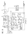
- Figure 13 is a schematic diagram showing a sixth embodiment of the present invention.
- the reference numeral 51 designates a magneto-optical disk
- the reference numeral 65 denotes magnetic film.
- the magneto-optical disk 51 is rotatively driven by a motor 64.
- the optical pick-up 63 contains therein a semiconductor laser 54 as a light source.
- a light emitted from the semiconductor laser 54 is transmitted through a collimator lens 53 and a beam splitter 55a, and is condensed on the magneto-optical disk 51 by an objective lens 52.
- the light reflected by the magneto-optical disk 51 again passes through the objective lens 52, is separated from the incident light by the beam splitter 55a, and the light is further divided into two lights by a beam splitter 55b, and one of the two lights is received by a photosensor 56a through a sensor lens 57a.
- a focus error signal and a track error signal are detected by an auto tracking and auto focusing (AT and AF) circuit 66.
- These error signals are input to an actuator 67 to drive the objective lens 52, whereby auto tracking and auto focusing are effected.
- the other light is further divided into two lights by a beam splitter 55c, and the respective lights are received by photosensors 56b and 56c through sensor lenses 57b and 57c.
- the sum of signals from the photosensors 56b and 56c is taken, whereby a reproduction signal is obtained.
- the optical pick-up 63 is designed such that the laser light of predetermined intensity continuously emitted from the semiconductor laser 54 is locally applied to the magnetic film 65 of the magneto-optical disk 51 to thereby cause the temperature of the magnetic film 65 in the irradiated portion to rise to the curie point or higher.
- the reference numeral 59 designates an electromagnet for applying a magnetic field to the magnetic film of the magneto-optical disk 51.
- this electromagnet 59 is operatively associated with the optical pick-up 63 with the magneto-optical disk 51 interposed therebetween so that the electromagnet may be movable radially of the magneto-optical disk.
- the reference numeral 60 denotes a magnetic field modulation circuit.
- the direction of an electric current flowing to a coil 58 wound on the electromagnet 59 is inverted in conformity with a recording signal input to the magnetic field modulation circuit 60. For example, when the signal level of the recording signal is a high level "1", an electric current flowing in a direction indicated by arrow I A is supplied to the coil 58, and when the signal level is a low level "0", an electric current flowing in a direction indicated by arrow I B is supplied to the coil 58.
- a magnetic field as indicated by arrow H A is produced when the signal level of the recording signal is the high level "1"
- a magnetic field as indicated by arrow H B is produced when the signal level of the recording signal is the low level "0".
- the magnetic fields indicated by arrows H A and H B differ in direction, but are equal in intensity. Also, when the intensity of the magnetic field indicated by arrow H A and the intensity of the magnetic field indicated by arrow H B are He and -He, respectively,
- a delay time calculation circuit 62 detects bit shift from the reproduction signal of a bit written on trial, and calculates a delay time for correcting the detected amount of shift. The calculated delay time is indicated to a delay circuit 61.
- the delay circuit 61 delays a signal input from a terminal 68 by the time indicated from the circuit 62 and sends it to the magnetic field modulation circuit 60.
- the operation of the above-described apparatus is performed in the following procedure.
- the optical pick-up 63 is first moved by a motor, not shown, to a location at which a light beam is to be applied to a desired track on the disk 51.
- a light beam is then applied to this track.
- a particular test signal is input from the terminal 68, and a magnetic field modulated in conformity with this test signal is applied from the electromagnet 59 to the disk 51. Thereby, the test signal is recorded on the disk 51.
- the power of the light beam is lowered to the reproduction level, and the track on which the test signal has been recorded is scanned by the light beam.
- the reflected light of this light beam reflected by the disk is received by the photosensors 56b and 56c, and the test signal is reproduced.
- the reproduced signal is sent to the delay time calculation circuit 62.
- the time from the synchronizing signal (a1) shown in Figure 2 till the rising of the reproduction signal (f1) is compared with the time from the synchronizing signal (a1) till the recording signal (b1), whereby the difference between these times is detected.
- the circuit 62 indicates the detected time difference as a delay time to the delay circuit 61.
- the power of the light beam is again heightened to the recording level.
- a signal to be recorded is then input from the terminal 68.
- the recording signal thus input is delayed by the delay circuit 61 by the time indicated from the circuit 62, and is sent to the magnetic field modulation circuit 60.
- the circuit 60 flows an electric current conforming to this recording signal to the coil 58, and applies a modulated magnetic field from the electromagnet 59 to the disk 51. On the track on the disk 51, the recording signal is overwritten on the test signal by the modulated magnetic field.
- the recording signal is recorded on the magneto-optical disk without causing bit shift.
- the above-described operation is all controlled by a central processing unit (CPU), not shown.
- the trial writing in the present embodiment need not always be effected each time the recording signal is input.
- the temperature of the recording medium may be detected at all times, and when the amount of variation in the temperature exceeds a predetermined value, the trial writing may be effected.
- the present invention permits various applications, besides the embodiments described above.
- the medium need not always be heated to the curie point by the light beam, but may be heated to a temperature at which there is provided such a coercive force that the direction of magnetization is inverted depending on the magnetic field applied.
- the present invention is also applicable to the so-called compensation temperature writing method in which the medium is heated to its compensation temperature.
- the medium is not limited to the disk-like shape, but may be of any shape such as a card-like shape or a tape-like shape.
- the present invention covers all of the above-described applications without departing from the scope thereof defined in the appended claims.
Applications Claiming Priority (8)
| Application Number | Priority Date | Filing Date | Title |
|---|---|---|---|
| JP5520789A JP2664463B2 (ja) | 1989-03-09 | 1989-03-09 | 光磁気記録再生装置 |
| JP55207/89 | 1989-03-09 | ||
| JP5520689A JP2670135B2 (ja) | 1989-03-09 | 1989-03-09 | 光磁気記録再生装置 |
| JP55206/89 | 1989-03-09 | ||
| JP5624689A JPH02236839A (ja) | 1989-03-10 | 1989-03-10 | 光磁気記録再生装置 |
| JP56246/89 | 1989-03-10 | ||
| JP177147/89 | 1989-07-11 | ||
| JP17714789A JPH0344846A (ja) | 1989-07-11 | 1989-07-11 | 光磁気記録装置 |
Publications (3)
| Publication Number | Publication Date |
|---|---|
| EP0387052A2 true EP0387052A2 (de) | 1990-09-12 |
| EP0387052A3 EP0387052A3 (en) | 1990-12-05 |
| EP0387052B1 EP0387052B1 (de) | 1995-09-20 |
Family
ID=27463164
Family Applications (1)
| Application Number | Title | Priority Date | Filing Date |
|---|---|---|---|
| EP90302466A Expired - Lifetime EP0387052B1 (de) | 1989-03-09 | 1990-03-08 | Magnetooptisches Aufzeichnungsgerät mit Mitteln zur Verzögerung des Eingangssignales zur Verhinderung von Bitverschiebung |
Country Status (3)
| Country | Link |
|---|---|
| US (1) | US5091897A (de) |
| EP (1) | EP0387052B1 (de) |
| DE (1) | DE69022451T2 (de) |
Cited By (1)
| Publication number | Priority date | Publication date | Assignee | Title |
|---|---|---|---|---|
| EP0529662A3 (en) * | 1991-08-30 | 1993-07-21 | Sony Corporation | Optical disc and method for recording on optical disk |
Families Citing this family (19)
| Publication number | Priority date | Publication date | Assignee | Title |
|---|---|---|---|---|
| JP2847722B2 (ja) * | 1988-06-24 | 1999-01-20 | ソニー株式会社 | 光磁気記録装置 |
| JPH03214441A (ja) * | 1990-01-18 | 1991-09-19 | Canon Inc | 光磁気記録装置 |
| JPH04132059A (ja) * | 1990-09-20 | 1992-05-06 | Mitsubishi Electric Corp | 光磁気ディスク装置 |
| DE4032871A1 (de) * | 1990-10-17 | 1992-04-23 | Bosch Gmbh Robert | Schaltungsanordnung zur abtastung optischer aufzeichnungstraeger |
| US5189567A (en) * | 1991-08-26 | 1993-02-23 | Eastman Kodak Company | High speed switching circuit for controlling current flow in a bridge circuit coil for use in a magneto-optic direct overwrite system |
| US5388085A (en) * | 1993-03-03 | 1995-02-07 | International Business Machines Corporation | Apparatus and method for accessing sectors of a rotating disk |
| JPH0969246A (ja) * | 1995-08-30 | 1997-03-11 | Canon Inc | 光学的情報記録再生装置 |
| JPH1092037A (ja) * | 1996-09-19 | 1998-04-10 | Canon Inc | 光磁気記録再生方法及び光磁気記録再生装置 |
| JPH10334534A (ja) * | 1997-05-28 | 1998-12-18 | Canon Inc | 光磁気記録再生方法及び光磁気記録再生装置 |
| JPH11134732A (ja) | 1997-08-29 | 1999-05-21 | Canon Inc | 情報記録再生方法 |
| JPH11353732A (ja) | 1998-06-10 | 1999-12-24 | Canon Inc | 光磁気記録再生方法及び装置 |
| JP2000200450A (ja) | 1998-10-30 | 2000-07-18 | Canon Inc | 光磁気記録再生方法及び装置 |
| JP2000149344A (ja) * | 1998-11-05 | 2000-05-30 | Hitachi Ltd | 情報記録方法、情報記録再生方法、情報再生方法、情報記録装置、情報記録再生装置及び情報再生装置 |
| JP2001023254A (ja) | 1999-07-02 | 2001-01-26 | Canon Inc | 光磁気記録テスト方法及び光磁気記録再生装置 |
| JP2003317344A (ja) * | 2002-04-26 | 2003-11-07 | Canon Inc | 光磁気記録方法、及び光磁気記録装置 |
| JP2005011385A (ja) * | 2003-06-16 | 2005-01-13 | Canon Inc | 磁区拡大型光磁気再生方法及び装置 |
| TWI250516B (en) * | 2004-04-22 | 2006-03-01 | Lite On It Corp | Laser power control method of optical disc recorder |
| JP2007122815A (ja) * | 2005-10-28 | 2007-05-17 | Canon Inc | 光ディスク装置の球面収差及びフォーカスオフセット調整方法、それを用いた光ディスク装置 |
| JP2008016165A (ja) * | 2006-07-10 | 2008-01-24 | Canon Inc | 記録パワー調整方法及び光ディスク装置 |
Family Cites Families (9)
| Publication number | Priority date | Publication date | Assignee | Title |
|---|---|---|---|---|
| JPS5753803A (en) * | 1980-09-17 | 1982-03-31 | Ricoh Co Ltd | Floppy disk device |
| JPS60205859A (ja) * | 1984-03-30 | 1985-10-17 | Sharp Corp | フロツピ−デイスクドライブ制御装置 |
| JPH0619863B2 (ja) * | 1984-06-13 | 1994-03-16 | 株式会社日立製作所 | 光磁気情報記憶方法及び装置 |
| JPH0664768B2 (ja) * | 1985-09-18 | 1994-08-22 | 松下電器産業株式会社 | 記録再生装置 |
| US4872078A (en) * | 1986-04-24 | 1989-10-03 | International Business Machines Corporation | Method and apparatus for encoding and direct overwriting of magneto-optic data |
| JP2575120B2 (ja) * | 1986-07-31 | 1997-01-22 | ソニー株式会社 | 光磁気記録装置 |
| JP2687350B2 (ja) * | 1987-05-28 | 1997-12-08 | ソニー株式会社 | 光磁気ディスク再生装置 |
| DE3728237A1 (de) * | 1987-08-25 | 1989-03-09 | Philips Patentverwaltung | Verfahren zum schreiben von binaerer information in eine magnetooptische speicherschicht und anordnung zur durchfuehrung des verfahrens |
| JP2647875B2 (ja) * | 1987-12-25 | 1997-08-27 | 株式会社日立製作所 | 光磁気信号記録再生方法 |
-
1990
- 1990-03-08 DE DE69022451T patent/DE69022451T2/de not_active Expired - Fee Related
- 1990-03-08 EP EP90302466A patent/EP0387052B1/de not_active Expired - Lifetime
-
1991
- 1991-03-18 US US07/670,530 patent/US5091897A/en not_active Expired - Lifetime
Cited By (2)
| Publication number | Priority date | Publication date | Assignee | Title |
|---|---|---|---|---|
| EP0529662A3 (en) * | 1991-08-30 | 1993-07-21 | Sony Corporation | Optical disc and method for recording on optical disk |
| US5345435A (en) * | 1991-08-30 | 1994-09-06 | Sony Corporation | Optical disc and method for recording on optical disc |
Also Published As
| Publication number | Publication date |
|---|---|
| EP0387052A3 (en) | 1990-12-05 |
| US5091897A (en) | 1992-02-25 |
| DE69022451T2 (de) | 1996-03-21 |
| EP0387052B1 (de) | 1995-09-20 |
| DE69022451D1 (de) | 1995-10-26 |
Similar Documents
| Publication | Publication Date | Title |
|---|---|---|
| EP0387052A2 (de) | Magnetooptisches Aufzeichnungsgerät mit Mitteln zur Verzögerung des Eingangssignales zur Verhinderung von Bitverschiebung | |
| EP0454038B1 (de) | Verfahren zur Regelung eines Aufzeichnungslaserstrahls | |
| US4736353A (en) | Disc accessing using coarse and fine actuators with the fine actuator locked during coarse actuator movement | |
| JPH05325210A (ja) | トラックジャンプ制御装置 | |
| US20020191511A1 (en) | Information recording/reproducing apparatus and method and information recording medium | |
| CN1060159A (zh) | 利用聚焦信号偏移获得最佳聚焦 | |
| EP0210623A2 (de) | Wiedergabegerät für optische Information | |
| EP0463959B1 (de) | Gerät für optische Platten | |
| JPH067413B2 (ja) | 光ピツクアツプのトラツキング制御方式 | |
| EP0400927A2 (de) | Aufzeichnungs- und Wiedergabegerät mit einem magnetooptischen Medium | |
| KR20030034989A (ko) | 배속 전환시점에서의 최적 기록방법 및 장치 | |
| KR0136709B1 (ko) | 광 자기기록 장치 | |
| EP0367094A2 (de) | Optischer Plattenspieler | |
| US5442604A (en) | Access control device | |
| JPH1139664A (ja) | 多層光記録媒体用フォーカス制御装置 | |
| EP0375266B1 (de) | Optisches Plattenaufzeichnungs- und/oder -wiedergabegerät | |
| EP0568009B1 (de) | Aufzeichnungsvorrichtung und Verfahren für eine magneto-optische Platte | |
| US5103440A (en) | Track access error correction apparatus for moving an optical head from one track location to another track location on an optical disc | |
| JP2607070B2 (ja) | 情報記録再生装置 | |
| JPH04310633A (ja) | フォーカスサーボ装置 | |
| JPH05182224A (ja) | 光ディスク装置 | |
| JPH10289466A (ja) | 光ディスク装置 | |
| JP3402631B2 (ja) | 光磁気記録再生装置 | |
| JP4148822B2 (ja) | 光ディスク装置及びその制御プログラム | |
| JPH01201829A (ja) | 光学的情報記録再生装置 |
Legal Events
| Date | Code | Title | Description |
|---|---|---|---|
| PUAI | Public reference made under article 153(3) epc to a published international application that has entered the european phase |
Free format text: ORIGINAL CODE: 0009012 |
|
| AK | Designated contracting states |
Kind code of ref document: A2 Designated state(s): DE FR GB IT NL |
|
| PUAL | Search report despatched |
Free format text: ORIGINAL CODE: 0009013 |
|
| AK | Designated contracting states |
Kind code of ref document: A3 Designated state(s): DE FR GB IT NL |
|
| 17P | Request for examination filed |
Effective date: 19901231 |
|
| 17Q | First examination report despatched |
Effective date: 19930623 |
|
| GRAA | (expected) grant |
Free format text: ORIGINAL CODE: 0009210 |
|
| AK | Designated contracting states |
Kind code of ref document: B1 Designated state(s): DE FR GB IT NL |
|
| REF | Corresponds to: |
Ref document number: 69022451 Country of ref document: DE Date of ref document: 19951026 |
|
| ET | Fr: translation filed | ||
| ITF | It: translation for a ep patent filed | ||
| PLBE | No opposition filed within time limit |
Free format text: ORIGINAL CODE: 0009261 |
|
| STAA | Information on the status of an ep patent application or granted ep patent |
Free format text: STATUS: NO OPPOSITION FILED WITHIN TIME LIMIT |
|
| 26N | No opposition filed | ||
| REG | Reference to a national code |
Ref country code: GB Ref legal event code: IF02 |
|
| PGFP | Annual fee paid to national office [announced via postgrant information from national office to epo] |
Ref country code: DE Payment date: 20040319 Year of fee payment: 15 |
|
| PGFP | Annual fee paid to national office [announced via postgrant information from national office to epo] |
Ref country code: GB Payment date: 20050222 Year of fee payment: 16 |
|
| PGFP | Annual fee paid to national office [announced via postgrant information from national office to epo] |
Ref country code: NL Payment date: 20050316 Year of fee payment: 16 |
|
| PGFP | Annual fee paid to national office [announced via postgrant information from national office to epo] |
Ref country code: FR Payment date: 20050330 Year of fee payment: 16 |
|
| PG25 | Lapsed in a contracting state [announced via postgrant information from national office to epo] |
Ref country code: DE Free format text: LAPSE BECAUSE OF NON-PAYMENT OF DUE FEES Effective date: 20051001 |
|
| PG25 | Lapsed in a contracting state [announced via postgrant information from national office to epo] |
Ref country code: GB Free format text: LAPSE BECAUSE OF NON-PAYMENT OF DUE FEES Effective date: 20060308 |
|
| PGFP | Annual fee paid to national office [announced via postgrant information from national office to epo] |
Ref country code: IT Payment date: 20060331 Year of fee payment: 17 |
|
| PG25 | Lapsed in a contracting state [announced via postgrant information from national office to epo] |
Ref country code: NL Free format text: LAPSE BECAUSE OF NON-PAYMENT OF DUE FEES Effective date: 20061001 |
|
| GBPC | Gb: european patent ceased through non-payment of renewal fee |
Effective date: 20060308 |
|
| NLV4 | Nl: lapsed or anulled due to non-payment of the annual fee |
Effective date: 20061001 |
|
| REG | Reference to a national code |
Ref country code: FR Ref legal event code: ST Effective date: 20061130 |
|
| PG25 | Lapsed in a contracting state [announced via postgrant information from national office to epo] |
Ref country code: FR Free format text: LAPSE BECAUSE OF NON-PAYMENT OF DUE FEES Effective date: 20060331 |
|
| PG25 | Lapsed in a contracting state [announced via postgrant information from national office to epo] |
Ref country code: IT Free format text: LAPSE BECAUSE OF NON-PAYMENT OF DUE FEES Effective date: 20070308 |