EP0387740B1 - Optische Faser zur Frequenzumwandlung - Google Patents
Optische Faser zur Frequenzumwandlung Download PDFInfo
- Publication number
- EP0387740B1 EP0387740B1 EP90104613A EP90104613A EP0387740B1 EP 0387740 B1 EP0387740 B1 EP 0387740B1 EP 90104613 A EP90104613 A EP 90104613A EP 90104613 A EP90104613 A EP 90104613A EP 0387740 B1 EP0387740 B1 EP 0387740B1
- Authority
- EP
- European Patent Office
- Prior art keywords
- fiber
- optical fiber
- range
- wavelength
- ring
- Prior art date
- Legal status (The legal status is an assumption and is not a legal conclusion. Google has not performed a legal analysis and makes no representation as to the accuracy of the status listed.)
- Expired - Lifetime
Links
- 239000013307 optical fiber Substances 0.000 title claims description 20
- 238000006243 chemical reaction Methods 0.000 title claims description 16
- 239000000835 fiber Substances 0.000 claims description 47
- 238000005086 pumping Methods 0.000 claims description 6
- 229910052761 rare earth metal Inorganic materials 0.000 claims description 4
- 229910052779 Neodymium Inorganic materials 0.000 claims description 3
- QEFYFXOXNSNQGX-UHFFFAOYSA-N neodymium atom Chemical compound [Nd] QEFYFXOXNSNQGX-UHFFFAOYSA-N 0.000 claims description 3
- 230000001902 propagating effect Effects 0.000 claims description 3
- VYPSYNLAJGMNEJ-UHFFFAOYSA-N Silicium dioxide Chemical compound O=[Si]=O VYPSYNLAJGMNEJ-UHFFFAOYSA-N 0.000 description 9
- 238000010586 diagram Methods 0.000 description 7
- 101710121003 Oxygen-evolving enhancer protein 3, chloroplastic Proteins 0.000 description 4
- GNPVGFCGXDBREM-UHFFFAOYSA-N germanium atom Chemical compound [Ge] GNPVGFCGXDBREM-UHFFFAOYSA-N 0.000 description 4
- 230000003287 optical effect Effects 0.000 description 4
- 239000000377 silicon dioxide Substances 0.000 description 4
- 238000004519 manufacturing process Methods 0.000 description 3
- 239000000463 material Substances 0.000 description 3
- -1 rare earth ion Chemical class 0.000 description 3
- 239000006185 dispersion Substances 0.000 description 2
- 229910052732 germanium Inorganic materials 0.000 description 2
- YBMRDBCBODYGJE-UHFFFAOYSA-N germanium oxide Inorganic materials O=[Ge]=O YBMRDBCBODYGJE-UHFFFAOYSA-N 0.000 description 2
- 239000011521 glass Substances 0.000 description 2
- 230000003993 interaction Effects 0.000 description 2
- 150000002500 ions Chemical class 0.000 description 2
- 238000000034 method Methods 0.000 description 2
- 229910001392 phosphorus oxide Inorganic materials 0.000 description 2
- LFGREXWGYUGZLY-UHFFFAOYSA-N phosphoryl Chemical class [P]=O LFGREXWGYUGZLY-UHFFFAOYSA-N 0.000 description 2
- 238000011084 recovery Methods 0.000 description 2
- 238000002834 transmittance Methods 0.000 description 2
- 230000001960 triggered effect Effects 0.000 description 2
- OAICVXFJPJFONN-UHFFFAOYSA-N Phosphorus Chemical compound [P] OAICVXFJPJFONN-UHFFFAOYSA-N 0.000 description 1
- 229920000297 Rayon Polymers 0.000 description 1
- 230000015572 biosynthetic process Effects 0.000 description 1
- 229910052681 coesite Inorganic materials 0.000 description 1
- 229910052906 cristobalite Inorganic materials 0.000 description 1
- 230000007423 decrease Effects 0.000 description 1
- 230000007547 defect Effects 0.000 description 1
- 238000001514 detection method Methods 0.000 description 1
- 239000002019 doping agent Substances 0.000 description 1
- 238000011156 evaluation Methods 0.000 description 1
- 229910052747 lanthanoid Inorganic materials 0.000 description 1
- 150000002602 lanthanoids Chemical class 0.000 description 1
- 239000011159 matrix material Substances 0.000 description 1
- 239000000203 mixture Substances 0.000 description 1
- 230000009022 nonlinear effect Effects 0.000 description 1
- 230000000737 periodic effect Effects 0.000 description 1
- 229910052698 phosphorus Inorganic materials 0.000 description 1
- 239000011574 phosphorus Substances 0.000 description 1
- 230000010287 polarization Effects 0.000 description 1
- 238000004321 preservation Methods 0.000 description 1
- 239000002964 rayon Substances 0.000 description 1
- 235000012239 silicon dioxide Nutrition 0.000 description 1
- 229910052682 stishovite Inorganic materials 0.000 description 1
- 229910052905 tridymite Inorganic materials 0.000 description 1
- 238000001429 visible spectrum Methods 0.000 description 1
Images


Classifications
-
- G—PHYSICS
- G02—OPTICS
- G02B—OPTICAL ELEMENTS, SYSTEMS OR APPARATUS
- G02B6/00—Light guides; Structural details of arrangements comprising light guides and other optical elements, e.g. couplings
- G02B6/02—Optical fibres with cladding with or without a coating
- G02B6/036—Optical fibres with cladding with or without a coating core or cladding comprising multiple layers
- G02B6/03605—Highest refractive index not on central axis
- G02B6/03611—Highest index adjacent to central axis region, e.g. annular core, coaxial ring, centreline depression affecting waveguiding
-
- G—PHYSICS
- G02—OPTICS
- G02F—OPTICAL DEVICES OR ARRANGEMENTS FOR THE CONTROL OF LIGHT BY MODIFICATION OF THE OPTICAL PROPERTIES OF THE MEDIA OF THE ELEMENTS INVOLVED THEREIN; NON-LINEAR OPTICS; FREQUENCY-CHANGING OF LIGHT; OPTICAL LOGIC ELEMENTS; OPTICAL ANALOGUE/DIGITAL CONVERTERS
- G02F1/00—Devices or arrangements for the control of the intensity, colour, phase, polarisation or direction of light arriving from an independent light source, e.g. switching, gating or modulating; Non-linear optics
- G02F1/35—Non-linear optics
- G02F1/37—Non-linear optics for second-harmonic generation
- G02F1/377—Non-linear optics for second-harmonic generation in an optical waveguide structure
- G02F1/383—Non-linear optics for second-harmonic generation in an optical waveguide structure of the optical fibre type
-
- H—ELECTRICITY
- H01—ELECTRIC ELEMENTS
- H01S—DEVICES USING THE PROCESS OF LIGHT AMPLIFICATION BY STIMULATED EMISSION OF RADIATION [LASER] TO AMPLIFY OR GENERATE LIGHT; DEVICES USING STIMULATED EMISSION OF ELECTROMAGNETIC RADIATION IN WAVE RANGES OTHER THAN OPTICAL
- H01S3/00—Lasers, i.e. devices using stimulated emission of electromagnetic radiation in the infrared, visible or ultraviolet wave range
- H01S3/05—Construction or shape of optical resonators; Accommodation of active medium therein; Shape of active medium
- H01S3/06—Construction or shape of active medium
- H01S3/063—Waveguide lasers, i.e. whereby the dimensions of the waveguide are of the order of the light wavelength
- H01S3/067—Fibre lasers
- H01S3/06708—Constructional details of the fibre, e.g. compositions, cross-section, shape or tapering
- H01S3/06729—Peculiar transverse fibre profile
Definitions
- the present invention relates to an optical fiber for frequency conversion, in particular frequency doubling and tripling.
- frequency doubling in a material is the property of the latter to convert a beam of frequency ⁇ into a beam of frequency 2 ⁇ . If ⁇ corresponds to a wavelength of 1.064 nm, the harmonic is in the green at 532 nm. It is a second order nonlinear effect.
- the doubling phenomenon is prohibited in materials with an inversion center, such as homogeneous glasses. It is therefore necessary to break this symmetry in the fiber to observe this conversion.
- the problem posed is obtaining a high conversion yield. For this it is necessary that the pump wave and the emitted wave move at the same speed, that is to say that the effective indices of the fiber for ⁇ and 2 ⁇ are equal.
- the break of symmetry necessary for the doubling is produced spontaneously or artificially by interaction of the material with the light at 3 or 2 ⁇ .
- the local susceptibility at point (r, ⁇ , z) is constructed from this interaction; it has a spatial distribution determined by the overlap of the modes supporting the waves ⁇ and 2 ⁇ .
- the propagating mode ⁇ being imposed, that of 2 ⁇ is ab initio free, and is determined by a condition of maximization of recoveries.
- the conversion efficiency remains low, around 1%.
- the object of the present invention is to produce an optical fiber having a conversion efficiency much higher than that of the optical fibers known up to now.
- the subject of the present invention is an optical fiber for frequency conversion, characterized in that the core of the fiber has a structure with an annular index profile with a single ring making it possible to achieve phase matching and optimum recovery of two natural modes of fiber propagation, one LP01 propagating the ⁇ wave and the other LP 0k the k ⁇ wave with 2 ⁇ k ⁇ 4 for at least one wavelength between 0.4 ⁇ m and 2 , 6 ⁇ m, the jump in index ⁇ n of the ring being between 2 x10 ⁇ 2 and 5 x 10 ⁇ 2, the internal radius r i of the ring being between 0.5 ⁇ m and 1.5 ⁇ m, and the outside radius r e of the ring being between 2 ⁇ m and 3.5 ⁇ m.
- ⁇ n is between 2 x 10 ⁇ 2 and 3 x 10 ⁇ 2.
- ⁇ n is between 3 x 10 ⁇ 2 and 5 x 10 ⁇ 2.
- the present invention also relates to a laser applying the fiber defined above.
- FIG. 1 shows very schematically the variations in the index of the core of a silica optical fiber according to the invention with an annular index profile.
- the index increases by a value ⁇ n.
- This index difference can be obtained by doping with germanium and / or phosphorus oxides.
- French patent n ° 87 14 286 of October 16, 1987 describes a process for manufacturing such a fiber.
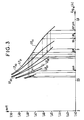
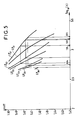
- Figures 2 to 5 are diagrams showing for different ⁇ n, r i and r e , the variations of the effective index n eff (on the ordinate) as a function of the wavelength ⁇ (log10 ⁇ on the abscissa) for different modes of propagation.
- LP01, LP02, LP03, LP04 correspond to modes of order 0, azimuth 0,1 or 2;
- LP11, LP12, LP13, LP14 correspond to modes of order 1, LP21, LP22, LP23, to modes of order 2 etc.
- the difference in log10 ⁇ for two modes having the same effective index is 0.3 for ⁇ and 2 ⁇ ; it is 0.5 for ⁇ and 3 ⁇ .
- a wave ⁇ is injected into the fiber in the LP01 mode.
- FIG. 2 also comprises the curve of the variations of the index n of the silica SiO2 as a function of ⁇ .
- the width of the non-critical range can be up to 0.4 ⁇ m.
- torque (r i , r e ) in the ranges indicated above for which there is a non-critical range for the desired wavelength whose width can range up to 0.4 ⁇ m.
- the non-critical range slides to shorter wavelengths as the thickness of the ring decreases.
- Examples II and III show that, if we give our a wavelength such as 1.32 ⁇ m or 1.54 ⁇ m, that is to say a telecommunication window center, there is a fiber structure having a ring with a ⁇ n 3 x 10 ⁇ 2 allowing to achieve an optimum agreement for ⁇ and 2 ⁇ .
- the conversion efficiency for and 2 ⁇ is at least equal to 50% with a pump wave of the order of 400 watts and a fiber a few meters in length.
- fibers according to the invention should be noted. These fibers always have a large ⁇ n at least equal to 2 x 10 ⁇ 2. In this case, it almost always appears during their manufacture a slight ellipticity which can be measured by birefringence and which is useful here to facilitate phase matching. The fiber has slightly different effective indices along two orthogonal axes and this gives a little latitude for the wavelength values.
- a very interesting application of the fibers according to the invention is the conversion of the optical frequencies used in the windows of optical telecommunications (800, 1300, 1550 and 2550 nm) so as to facilitate detection.
- a fiber according to the invention is particularly advantageous in an autocorrelator with optical fibers.
- Optical autocorrelation technique for duration evaluation of ultra-short light pulses emitted in the infrared is described in particular in the article "Autocorrelation of short pulses using a single-mode fiber" by U. Osterberg and W. Margulis, IEEE J. Quant. Electronics, QE-24, October 1988, p. 2127-2129.
- Fiber optic lasers are already known; they contain doped fibers of different rare earths. Table I below gives the ions already used and the corresponding emission wavelengths.
- this type of doped fiber laser operates, for example, in triggered mode and in blocked mode, the peak power inside the cavity at the laser wavelength can reach 6 to 7 kW (see article by IN DULING , L. GOLDBERG, JF WELLER, Electronics Letters, 24 (1988), p. 1333).
- the peak power inside the cavity at the laser wavelength can reach 6 to 7 kW (see article by IN DULING , L. GOLDBERG, JF WELLER, Electronics Letters, 24 (1988), p. 1333).
- the fiber serves both as an amplifying laser medium and as an intracavity frequency doubler.
- a trigger 15 In the cavity can optionally be inserted a trigger 15, a mode blocker 16 and if necessary a collimation optic 18.
- the transmittance of the input mirror 12 is maximum at the length of pumping wave and minimum at the laser wavelength ⁇ and at the wavelength ⁇ / 2.
- the transmittance of the output mirror is minimal at the pumping wavelength, at the laser wavelength ⁇ and is adjusted to the wavelength ⁇ / 2 for the use considered.
- a laser emission wavelength we choose a rare earth ion (see Table I). This then fixes a pump wavelength compatible with the silica-based fiber doped with the chosen rare earth ion. Knowing the laser emission wavelength, it is possible to define the parameters of the germanium-doped silica ring corresponding to the core according to the invention in order to obtain the doubling of the laser emission frequency. We can then determine the LP01 profile and therefore the most efficient distribution of the rare earth ion in the fiber.
- the pump wavelength may be used 0.82 ⁇ m (0.8 ⁇ m ⁇ ⁇ ⁇ 0.830 ⁇ m). This wavelength can be delivered by a pumping source constituted by an array of power laser diodes.
- the laser emission wavelength of the neodymium is between 1.06 and 1.09 ⁇ m. In the case of a fiber according to the invention heavily doped with germanium, the laser emission wavelength is close to 1.09 ⁇ m.
- the peak power of the strongest pulse can be around several kilowatts inside the optical fiber.
- the conversion efficiency can be of the order of 50%.
- the wavelength obtained is approximately 0.545 ⁇ m.
Landscapes
- Physics & Mathematics (AREA)
- Optics & Photonics (AREA)
- Nonlinear Science (AREA)
- Electromagnetism (AREA)
- General Physics & Mathematics (AREA)
- Engineering & Computer Science (AREA)
- Plasma & Fusion (AREA)
- Lasers (AREA)
- Optical Fibers, Optical Fiber Cores, And Optical Fiber Bundles (AREA)
Claims (6)
- Lichtleitfaser zur Frequenzumwandlung, dadurch gekennzeichnet, daß der Kern der Faser eine Struktur eines einzigen Rings mit ringförmigem Brechungsindexprofil aufweist, die es ermöglicht, die Phasenabstimmung und die optimale Überdeckung von zwei Ausbreitungseigenmodi der Faser zu bewirken, von denen der eine LP₀₁ die Welle ω und der andere LP0k die Welle kω, wobei 2 ≦ k ≦ 4 ist, für mindestens eine zwischen 0,4 µm und 2,6 µm liegende Wellenlänge überträgt, wobei der Brechungsindexsprung Δn des Ringes zwischen 2 x 10⁻⁴ und 5 x 10⁻², der Innendurchmesser ri des Ringes zwischen 0,5 µm und 1,5 µm, und der Außendurchmesser re des Ringes zwischen 2 µm und 3,5 µm liegt.
- Lichtleitfaser nach Anspruch 1, dadurch gekennzeichnet, daß für die Frequenzverdoppelung der Wert Δn zwischen 2 x 10⁻² und 3 x 10⁻² liegt.
- Lichtleitfaser nach Anspruch 1, dadurch gekennzeichnet, daß zur Frequenzverdreifachung der Wert Δn zwischen 3 x 10⁻² und 5 x 10⁻² liegt.
- Lichtleitfaser nach einem der vorhergehenden Ansprüche, dadurch gekennzeichnet, daß sie eine leicht elliptische Form besitzt.
- Anwendung einer Lichtleitfaser gemäß einem der vorhergehenden Ansprüche auf eine Laserfaser, die mit dem Ion einer seltenen Erde dotiert ist.
- Anwendung nach Anspruch 5, dadurch gekennzeichnet, daß die Faser mit Neodym dotiert ist, daß die Pumpquelle aus einem Leistungslaserdiodengitter besteht, und daß die Emissionswellenlänge ungefähr 0,545 µm beträgt.
Applications Claiming Priority (2)
| Application Number | Priority Date | Filing Date | Title |
|---|---|---|---|
| FR8903475A FR2644593B1 (fr) | 1989-03-16 | 1989-03-16 | Fibre optique pour la conversion de frequence |
| FR8903475 | 1989-03-16 |
Publications (2)
| Publication Number | Publication Date |
|---|---|
| EP0387740A1 EP0387740A1 (de) | 1990-09-19 |
| EP0387740B1 true EP0387740B1 (de) | 1993-09-01 |
Family
ID=9379768
Family Applications (1)
| Application Number | Title | Priority Date | Filing Date |
|---|---|---|---|
| EP90104613A Expired - Lifetime EP0387740B1 (de) | 1989-03-16 | 1990-03-12 | Optische Faser zur Frequenzumwandlung |
Country Status (5)
| Country | Link |
|---|---|
| US (1) | US5106176A (de) |
| EP (1) | EP0387740B1 (de) |
| CA (1) | CA2012221C (de) |
| DE (1) | DE69002974T2 (de) |
| FR (1) | FR2644593B1 (de) |
Families Citing this family (7)
| Publication number | Priority date | Publication date | Assignee | Title |
|---|---|---|---|---|
| JPH04251830A (ja) * | 1991-01-28 | 1992-09-08 | Idemitsu Kosan Co Ltd | 有機光論理素子 |
| FR2707767B1 (fr) * | 1993-07-13 | 1995-08-25 | Alsthom Cge Alcatel | Amplificateur à fibre optique à conversion de fréquence. |
| SE507445C2 (sv) | 1996-03-22 | 1998-06-08 | Ericsson Telefon Ab L M | Optiskt element |
| ATE418743T1 (de) * | 2001-03-30 | 2009-01-15 | Ocg Technology Licensing Llc | Ringkernfaser |
| US7339721B1 (en) * | 2007-02-28 | 2008-03-04 | Corning Incorporated | Optical fiber light source based on third-harmonic generation |
| US8469335B2 (en) | 2010-06-14 | 2013-06-25 | Baker Hughes Incorporated | Pressure energized spring seal |
| JP6368279B2 (ja) * | 2015-05-26 | 2018-08-01 | 日本電信電話株式会社 | 数モード光ファイバ、及び光ファイバ伝送システム |
Family Cites Families (6)
| Publication number | Priority date | Publication date | Assignee | Title |
|---|---|---|---|---|
| US4082420A (en) * | 1972-11-25 | 1978-04-04 | Sumitomo Electric Industries, Ltd. | An optical transmission fiber containing fluorine |
| JPS63199328A (ja) * | 1987-02-16 | 1988-08-17 | Fuji Photo Film Co Ltd | 光波長変換素子 |
| JPH01105220A (ja) * | 1987-07-20 | 1989-04-21 | Fuji Photo Film Co Ltd | 光波長変換素子 |
| US4877304A (en) * | 1987-09-09 | 1989-10-31 | Corning Incorporated | Few-mode/single-mode fiber |
| EP0307896B1 (de) * | 1987-09-14 | 1994-02-09 | Fuji Photo Film Co., Ltd. | Verfahren zur Umwandlung der optischen Wellenlänge und optischer Wellenlängen-Konverter-Modul |
| DE68924188T2 (de) * | 1988-03-25 | 1996-02-15 | Fuji Photo Film Co Ltd | Optischer Wellenlängenkonverter. |
-
1989
- 1989-03-16 FR FR8903475A patent/FR2644593B1/fr not_active Expired - Lifetime
-
1990
- 1990-03-12 EP EP90104613A patent/EP0387740B1/de not_active Expired - Lifetime
- 1990-03-12 US US07/495,830 patent/US5106176A/en not_active Expired - Lifetime
- 1990-03-12 DE DE90104613T patent/DE69002974T2/de not_active Expired - Fee Related
- 1990-03-15 CA CA002012221A patent/CA2012221C/fr not_active Expired - Fee Related
Non-Patent Citations (3)
| Title |
|---|
| APPLIED PHYSICS LETTERS, vol. 39, no. 6, septembre 1981, pp 466-468, New York, US; Y. SASAKI et al.: "Phase-matched sum-frequency light generation in optical fibres". * |
| OPTICS LETTERS, vol. 13, no. 9, septembre 1988, pp 773-775, New York, US; M.A. SAIFI et al.: "Second-harmonic generation in single-mode and multimode fibers". * |
| PATENT ABSTRACTS OF JAPAN, vol. 7, no. 67 (P-184)(1212), 19 Mars 1983 & JP A 57211125 * |
Also Published As
| Publication number | Publication date |
|---|---|
| EP0387740A1 (de) | 1990-09-19 |
| US5106176A (en) | 1992-04-21 |
| CA2012221C (fr) | 1993-07-20 |
| FR2644593B1 (fr) | 1991-05-17 |
| FR2644593A1 (fr) | 1990-09-21 |
| DE69002974D1 (de) | 1993-10-07 |
| CA2012221A1 (fr) | 1990-09-16 |
| DE69002974T2 (de) | 1994-03-17 |
Similar Documents
| Publication | Publication Date | Title |
|---|---|---|
| Cohen et al. | A universal fiber-optic (UFO) measurement system based on a near-IR fiber Raman laser | |
| Sharp et al. | 190-fs passively mode-locked thulium fiber laser with a low threshold | |
| Jain et al. | A high‐efficiency tunable cw Raman oscillator | |
| US4784450A (en) | Apparatus for generating and amplifying new wavelengths of optical radiation | |
| Miller et al. | A Nd3+-doped cw fiber laser using all-fiber reflectors | |
| FR2660493A1 (fr) | Dispositif laser a changeur de frequence integre de facon monolithique. | |
| Britton et al. | Optical parametric oscillation in periodically poled lithium niobate driven by a diode-pumped Q-switched erbium fiber laser | |
| EP0451047A1 (de) | Vor Umwelteinflüssen geschützte integrierte optische Komponente und Verfahren zu ihrer Herstellung | |
| Li et al. | An efficient all-fiber variable optical attenuator via acoustooptic mode coupling | |
| EP0387740B1 (de) | Optische Faser zur Frequenzumwandlung | |
| Abedin | Single-frequency Brillouin lasing using single-mode As2Se3 chalcogenide fiber | |
| EP0473496A1 (de) | Verfahren zur Herstellung einer monomoden optischen Faser aus elektrooptischem Polymer, sowie eine solche optische Faser | |
| Yan et al. | Highly stable, flexible delivery of microjoule-level ultrafast pulses in vacuumized anti-resonant hollow-core fibers for active synchronization | |
| Rosker et al. | Widely tunable optical parametric oscillator using urea | |
| Covey et al. | All-optical switching with 1-ps response time in a DDMEBT enabled silicon grating coupler/resonator hybrid device | |
| Juhasz et al. | Efficient short-pulse generation from a diode-pumped Nd: YLF laser with a piezoelectrically induced diffraction modulator | |
| TWI426671B (zh) | 電光晶體布拉格折射器及以其作為雷射q調制器的方法 | |
| EP3885827A1 (de) | Multimode-wellenleiter, der konfiguriert ist, um singlemode-strahlung aus singlemode-strahlung zu erzeugen | |
| EP2399163B1 (de) | Optische einrichtung zur erzeugung von polychromatischem licht | |
| Lv et al. | High-efficiency mode-locked fiber laser with a switchable oscillating transverse mode in an all few-mode fiber linear cavity | |
| Chang et al. | Active Q-switching in an erbium-doped fiber laser using an ultrafast silicon-based variable optical attenuator | |
| Abdulhalim et al. | Acoustooptic in-fiber modulator using acoustic focusing | |
| Kiani et al. | Silicon-thulium hybrid microdisk lasers with low threshold and wide emission wavelength range | |
| Kean et al. | Experimental evaluation of a fibre Raman oscillator having fibre grating reflectors | |
| Hellström et al. | Efficient nanosecond optical parametric oscillators based on periodically poled KTP emitting in the 1.8–2.5-µ m spectral region |
Legal Events
| Date | Code | Title | Description |
|---|---|---|---|
| PUAI | Public reference made under article 153(3) epc to a published international application that has entered the european phase |
Free format text: ORIGINAL CODE: 0009012 |
|
| AK | Designated contracting states |
Kind code of ref document: A1 Designated state(s): DE FR GB IT NL |
|
| 17P | Request for examination filed |
Effective date: 19901227 |
|
| 17Q | First examination report despatched |
Effective date: 19921105 |
|
| GRAA | (expected) grant |
Free format text: ORIGINAL CODE: 0009210 |
|
| AK | Designated contracting states |
Kind code of ref document: B1 Designated state(s): DE FR GB IT NL |
|
| GBT | Gb: translation of ep patent filed (gb section 77(6)(a)/1977) |
Effective date: 19930831 |
|
| REF | Corresponds to: |
Ref document number: 69002974 Country of ref document: DE Date of ref document: 19931007 |
|
| ITF | It: translation for a ep patent filed | ||
| PLBE | No opposition filed within time limit |
Free format text: ORIGINAL CODE: 0009261 |
|
| STAA | Information on the status of an ep patent application or granted ep patent |
Free format text: STATUS: NO OPPOSITION FILED WITHIN TIME LIMIT |
|
| 26N | No opposition filed | ||
| PGFP | Annual fee paid to national office [announced via postgrant information from national office to epo] |
Ref country code: GB Payment date: 19990212 Year of fee payment: 10 |
|
| PGFP | Annual fee paid to national office [announced via postgrant information from national office to epo] |
Ref country code: FR Payment date: 19990216 Year of fee payment: 10 |
|
| PGFP | Annual fee paid to national office [announced via postgrant information from national office to epo] |
Ref country code: DE Payment date: 19990224 Year of fee payment: 10 |
|
| PGFP | Annual fee paid to national office [announced via postgrant information from national office to epo] |
Ref country code: NL Payment date: 19990228 Year of fee payment: 10 |
|
| PG25 | Lapsed in a contracting state [announced via postgrant information from national office to epo] |
Ref country code: GB Free format text: LAPSE BECAUSE OF NON-PAYMENT OF DUE FEES Effective date: 20000312 |
|
| PG25 | Lapsed in a contracting state [announced via postgrant information from national office to epo] |
Ref country code: NL Free format text: LAPSE BECAUSE OF NON-PAYMENT OF DUE FEES Effective date: 20001001 |
|
| GBPC | Gb: european patent ceased through non-payment of renewal fee |
Effective date: 20000312 |
|
| PG25 | Lapsed in a contracting state [announced via postgrant information from national office to epo] |
Ref country code: FR Free format text: LAPSE BECAUSE OF NON-PAYMENT OF DUE FEES Effective date: 20001130 |
|
| NLV4 | Nl: lapsed or anulled due to non-payment of the annual fee |
Effective date: 20001001 |
|
| REG | Reference to a national code |
Ref country code: FR Ref legal event code: ST |
|
| PG25 | Lapsed in a contracting state [announced via postgrant information from national office to epo] |
Ref country code: DE Free format text: LAPSE BECAUSE OF NON-PAYMENT OF DUE FEES Effective date: 20010103 |
|
| PG25 | Lapsed in a contracting state [announced via postgrant information from national office to epo] |
Ref country code: IT Free format text: LAPSE BECAUSE OF NON-PAYMENT OF DUE FEES;WARNING: LAPSES OF ITALIAN PATENTS WITH EFFECTIVE DATE BEFORE 2007 MAY HAVE OCCURRED AT ANY TIME BEFORE 2007. THE CORRECT EFFECTIVE DATE MAY BE DIFFERENT FROM THE ONE RECORDED. Effective date: 20050312 |